Table of Contents
Advertisement
Quick Links
Digital Energy
Multilin
Software Revision: 2.2x
Manual P/N: 1601-0118-AD
Manual Order Code: GEK-106435M
Copyright © 2010 GE Multilin
GE Multilin
215 Anderson Avenue, Markham, Ontario
Canada L6E 1B3
Tel: (905) 294-6222 Fax: (905) 201-2098
Internet:
http://www.GEmultilin.com
*1601-0118-AD*
PQMII Power Quality Meter
Instruction Manual
GE Multilin's Quality Management
System is registered to ISO9001:2000
QMI # 005094
UL # A3775
Advertisement
Table of Contents

Related Manuals for GE PQMII


Summary of Contents for GE PQMII
- Page 1 Digital Energy Multilin PQMII Power Quality Meter Instruction Manual Software Revision: 2.2x Manual P/N: 1601-0118-AD Manual Order Code: GEK-106435M Copyright © 2010 GE Multilin GE Multilin 215 Anderson Avenue, Markham, Ontario Canada L6E 1B3 Tel: (905) 294-6222 Fax: (905) 201-2098 Internet: http://www.GEmultilin.com...
- Page 2 The contents of this manual are the property of GE Multilin Inc. This documentation is furnished on license and may not be reproduced in whole or in part without the permission of GE Multilin. The content of this manual is for informational use only and is subject to change without notice.
-
Page 3: Table Of Contents
VT I ..........................2-13 NPUTS CT I ..........................2-13 NPUTS ........................2-14 UTPUT ELAYS ) ....................2-14 WITCH NPUTS PTIONAL ) ..................2-16 NALOG UTPUTS PTIONAL ) ....................2-17 NALOG NPUT PTIONAL PQMII POWER QUALITY METER – INSTRUCTION MANUAL TOC–I... - Page 4 ........................4-8 ESCRIPTION .................... 4-8 AVING ETPOINTS TO A ....................4-8 OADING IRMWARE ....................4-10 OADING AVED ETPOINTS USING THE ENERVISTA PQMII SETUP SOFTWARE ............. 4-11 ......................4-11 NTERING ETPOINTS ....................4-12 IEWING CTUAL ALUES ........................4-12 ETPOINT ILES ........................4-12 ETTING POWER ANALYSIS ..........................
- Page 5 ........................5-53 NALOG NPUT ........................5-53 WITCH NPUTS ......................5-54 ACTORY ACTUAL VALUES VIEWING ......................6-1 6: MONITORING ........................6-1 ESCRIPTION ...................... 6-2 CTUAL ALUES A1 METERING ............................. 6-4 ......................6-4 URRENT ETERING PQMII POWER QUALITY METER – INSTRUCTION MANUAL TOC–III...
- Page 6 ........................7-23 ESCRIPTION PQMII P KYZ T ....7-23 ULSE NPUT WITH A ULSE NITIATOR USING ERMINALS PULSE TOTALIZER APPLICATION ....................7-24 ........................7-24 ESCRIPTION ........7-24 OTALIZING NERGY FROM ULTIPLE ETERING OCATIONS TOC–IV PQMII POWER QUALITY METER – INSTRUCTION MANUAL...
- Page 7 ETPOINTS ........................A-3 CTUAL ALUES STEP ............... A-4 ONDITIONS EQUIRED TO NERGIZE A ................A-5 DDITIONS TO ODBUS EMORY REVISION HISTORY .......................... A-7 ........................A-7 ELEASE ATES ........................A-7 ELEASE OTES INDEX PQMII POWER QUALITY METER – INSTRUCTION MANUAL TOC–V...
- Page 8 TABLE OF CONTENTS TOC–VI PQMII POWER QUALITY METER – INSTRUCTION MANUAL...
-
Page 9: Description
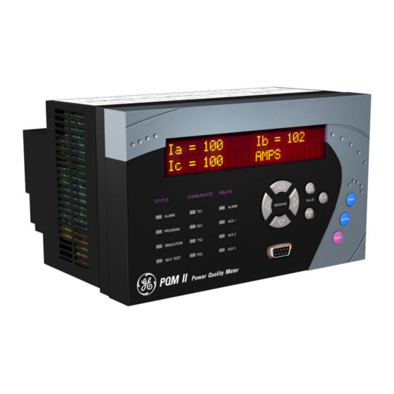
1.1.1 Description The GE Multilin PQMII Power Quality Meter is an ideal choice for continuous monitoring of a single or three-phase system. It provides metering for current, voltage, real power, reactive power, apparent power, energy use, cost of power, power factor, and frequency. -
Page 10: Feature Highlights
• Metering of distribution feeders, transformers, generators, capacitor banks, and motors • Medium and low voltage three-phase systems • Commercial, industrial, utility • Flexible control for demand load shedding, power factor, etc. • Power quality analysis • System debugging 1–2 PQMII POWER QUALITY METER – INSTRUCTION MANUAL... - Page 11 Four (4) Alarm output Instrumentation control relays COM 2 Electrical Maintenance 4 to 20 mA Four (4) RS232 transducer PORT outputs PC running EnerVista PQMII Setup 746701A1.CDR FIGURE 1–1: Single Line Diagram PQMII POWER QUALITY METER – INSTRUCTION MANUAL 1–3...
- Page 12 CHAPTER 1: OVERVIEW FIGURE 1–2: Feature Highlights 1–4 PQMII POWER QUALITY METER – INSTRUCTION MANUAL...
-
Page 13: Standard Features
This can be used to integrate process, instrumentation, and electrical requirements in a plant automation system by connecting several PQMII meters together to a DCS or SCADA system. A PC running the EnerVista PQMII Setup Software can change system setpoints and monitor values, status, and alarms. Continuous monitoring minimizes process downtime by immediately identifying potential problems due to faults or changes from growth. -
Page 14: Open Architecture
1.2.5 Open Architecture PQMII units can initially be used as standalone meters. Their open architecture allows connection to other Modbus compatible devices on the same communication link. These can be integrated in a complete plant-wide system for overall process monitoring and control. -
Page 15: Optional Features
• underfrequency/demand output for load shedding resulting in power cost saving • kWh, kvarh and kVAh pulse output for PLC interface • Pulse input for totalizing quantities such as kWh, kvarh, kVAh, etc. PQMII POWER QUALITY METER – INSTRUCTION MANUAL 1–7... -
Page 16: Power Analysis Option
FIGURE 1–6: Harmonic Spectrum 1–8 PQMII POWER QUALITY METER – INSTRUCTION MANUAL... - Page 17 CHAPTER 1: OVERVIEW Voltage and current waveforms can be captured and displayed on a PC with the EnerVista PQMII Setup Software or EnerVista Viewpoint. Distorted peaks or notches from SCR switching provide clues for taking corrective action. FIGURE 1–7: Captured Waveform Alarms, triggers, and input/output events can be stored in a 150-event record and time/ date stamped by the internal clock.
- Page 18 For additional information on waveform sampling and analysis features, see Power Analysis on page 4–13. The power analysis option also provides a Trace Memory feature. This feature can be used to record specified parameters based on the user defined triggers. 1–10 PQMII POWER QUALITY METER – INSTRUCTION MANUAL...
- Page 19 CHAPTER 1: OVERVIEW FIGURE 1–9: Trace Memory Capture PQMII POWER QUALITY METER – INSTRUCTION MANUAL 1–11...
-
Page 20: Enervista Pqmii Setup Software
1.4.1 Overview All data continuously gathered by the PQMII can be transferred to a third party software program for display, control, or analysis through the communications interface. The EnerVista PQMII Setup Software allows the user to view and manipulate this data and assists in programming the PQMII. -
Page 21: Order Codes
• EnerVista PQMII Setup Software (included with the PQMII; also available at http:// www.enerVista.com) • RS232 to RS485 converter (required to connect a PC to the PQMII RS485 ports) • GE MultiNET RS485 serial-to-Ethernet converter (required for connection to an Ethernet network) •... -
Page 22: Specifications
Isolation:............±36 V DC isolated, active source PULSE OUTPUT Parameters:..........+kWh, –kWh, +kvarh, –kvarh, kVAh Interval:............1 to 65000 in steps of 1 Pulse width: ..........100 to 2000 ms in steps of 10 Minimum pulse interval: ......500 ms Accuracy:............±10 ms 1–14 PQMII POWER QUALITY METER – INSTRUCTION MANUAL... -
Page 23: Trace Memory Trigger
0.3 A at 250 V DC Inductive (L/R = 7 ms): ......5 A at 30 V DC, 125/250 V AC 0.25 A at 125 V DC 0.15 A at 250 V DC PQMII POWER QUALITY METER – INSTRUCTION MANUAL 1–15... -
Page 24: Metering
Dropout: ............103% of pickup Time delay: ...........0.5 to 600.0 s in steps of 0.5 Phases:............Any 1 / Any 2 / All 3 (programmable) have to be ≤ pickup to operate Accuracy:............per voltage input 1–16 PQMII POWER QUALITY METER – INSTRUCTION MANUAL... - Page 25 Phases recorded: ........all three phases recorded independently Conversion: ..........true RMS, 8 samples/half-cycle Sag: Pickup level: ..........0.20 to 0.90 × VT in steps of 0.01 Dropout level: .......... pickup + 10% of nominal PQMII POWER QUALITY METER – INSTRUCTION MANUAL 1–17...
-
Page 26: System
Power: .............nominal 10 VA, max. 20 VA Holdup: ............100 ms typical (at 120 V AC / 125 V DC) It is recommended that the PQMII be powered up at least once per year to avoid deterioration of the electrolytic capacitors in the power supply. - Page 27 C22.2.No 14 Manufactured under a registered ISO9001 quality program ENVIRONMENTAL Ambient temperatures: Operating range: -10C to 60C Operating up to 95% (non condensing) @ 55C (As per Humidity: IEC60068-2-30 Variant 2, 6days) PQMII POWER QUALITY METER – INSTRUCTION MANUAL 1–19...
-
Page 28: Physical
Ventilation may be required in enclosures exposed to direct sunlight. Cleaning: May be cleaned with a damp cloth. 1.6.9 Physical PACKAGING Shipping box: ..........8½” × 6” × 6” (L × H × D) 21.5cm × 15.2cm × 15.2 cm 1–20 PQMII POWER QUALITY METER – INSTRUCTION MANUAL... -
Page 29: Mounting
Physical dimensions and required cutout dimensions for the PQMII are shown below. Once the cutout and mounting holes are made in the panel, use the eight #6 self-tapping screws provided to secure the PQMII. Mount the unit on a panel or switchgear door to allow operator access to the keypad and indicators. -
Page 30: Product Identification
(the format is 1601-nnnn- ). The firmware revision is located on that same page, just above the revision manual part number, and is also loaded in the PQMII, where it can be viewed by scrolling to the message. A4 PRODUCT INFO... -
Page 31: Electrical Configuration
Phase C CT 1A Aux1 relay NO Phase C CT COM Alarm relay NC Neutral CT 5A Alarm relay COM Neutral CT 1A Alarm relay NO Neutral CT COM Comm 1 COM PQMII POWER QUALITY METER – INSTRUCTION MANUAL 2–3... - Page 32 Comm 1 – Signal Upper Row (21 to 51) Analog shield Comm 1 + Analog in – Comm 2 COM Analog in + Comm 2 – Analog out com Comm 2 + 2–4 PQMII POWER QUALITY METER – INSTRUCTION MANUAL...
-
Page 33: Wiring Diagrams
This wiring diagram below shows the typical 4-wire wye connection which will cover any voltage range. Select the S2 SYSTEM SETUP CURRENT/VOLTAGE CONFIGURATION setpoint “4 Wire Wye (3 VTs)” WIRING: FIGURE 2–3: Wiring Diagram 4-wire Wye (3 VTs) PQMII POWER QUALITY METER – INSTRUCTION MANUAL 2–5... - Page 34 Select the S2 SYSTEM SETUP CURRENT/VOLTAGE setpoint. CONFIGURATION VT WIRING: “4 WIRE WYE (2 VTs)” This wiring configuration will only provide accurate power measurements if the voltages are balanced. 2–6 PQMII POWER QUALITY METER – INSTRUCTION MANUAL...
- Page 35 CHAPTER 2: INSTALLATION FIGURE 2–4: Wiring Diagram 4-wire Wye (2 VTs) Four-wire systems with voltages 347 V L-N or less can be directly connected to the PQMII without VTs. Select the S2 SYSTEM SETUP CURRENT/VOLTAGE CONFIGURATION VT WIRING: “4 setpoint.
- Page 36 CHAPTER 2: INSTALLATION The PQMII voltage inputs should be directly connected using HRC fuses rated at 2 A to ensure adequate interrupting capacity. FIGURE 2–5: Wiring Diagram 4-wire Wye Direct (No VTs) 2–8 PQMII POWER QUALITY METER – INSTRUCTION MANUAL...
- Page 37 This diagram shows the typical 3-wire delta connection which will cover any voltage range. Select the S2 SYSTEM SETUP CURRENT/VOLTAGE CONFIGURATION VT WIRING: “3 WIRE DELTA (2 setpoint. VTs)” FIGURE 2–6: Wiring Diagram 3-wire Delta (2 VTs) PQMII POWER QUALITY METER – INSTRUCTION MANUAL 2–9...
- Page 38 CHAPTER 2: INSTALLATION Three-wire systems with voltages 600 V (L-L) or less can be directly connected to the PQMII without VTs. Select the S2 SYSTEM SETUP CURRENT/VOLTAGE CONFIGURATION VT WIRING: “3 setpoint. WIRE DIRECT” The PQMII voltage inputs should be directly connected using HRC fuses rated at 2 amps to ensure adequate interrupting capacity.
- Page 39 For a single-phase connection, connect current and voltage to the phase A inputs only. All other inputs are ignored. Select the S2 SYSTEM SETUP CURRENT/VOLTAGE CONFIGURATION setpoint. WIRING: “SINGLE PHASE” FIGURE 2–8: Single Phase Connection PQMII POWER QUALITY METER – INSTRUCTION MANUAL 2–11...
-
Page 40: 3-Wire System Using Two Cts
A and C to the phase B input on the PQMII. This causes the phase A and phase C current to flow through the PQMII’s phase B CT in the opposite direction, producing a current equal to the actual phase B current. -
Page 41: Control Power
A universal AC/DC power supply is standard on the PQMII. It covers the range 90 to 300 V DC and 70 to 265 V AC at 50/60 Hz. It is not necessary to adjust the PQMII if the control voltage is within this range. A low voltage power supply is available as an option. It covers the range 20 to 60 V DC and 24 to 48 V AC at 50/60 Hz. -
Page 42: Output Relays
2.2.7 Output Relays The basic PQMII comes equipped with one output relay; the control option supplies three additional output relays. The PQMII output relays have form C contacts (normally open (NO), normally closed (NC), and common (COM)). The contact rating for each relay is 5 A resistive and 5 A inductive at 250 V AC. - Page 43 The minimum pulse width required for the PQMII to read the switch is 150 ms. Therefore, for the PQMII to read one pulse, the switch input must be in its inactive state (closed/open) for a minimum of 150 ms then in its active state (open/ closed) for another 150 ms.
-
Page 44: Analog Outputs (Optional)
2.2.9 Analog Outputs (Optional) The PQMII has four current outputs when the transducer option is installed (T20 = 4 to 20 mA, T1 = 0 to 1 mA in the order code). These outputs can be multiplexed to produce 8 analog transducers. -
Page 45: Analog Input (Optional)
PQMII. See 5.3.3: Analog Input for details on programming the analog input. 2.2.11 RS485 Serial Ports A fully loaded PQMII is equipped with three serial ports. COM1 is a RS485 port available at the rear terminals of the PQMII which is normally used as the main communications interface to the system. - Page 46 Therefore, it is imperative that the serial master and PQMII are both at the same ground potential. This is accomplished by joining the RS485 ground terminal (Terminal 46 for COM1;...
-
Page 47: 2.2.12 Rs232 Front Panel Port
It may be required to test the complete switchgear for dielectric strength with the PQMII installed. This is also known as “flash” or “hipot” testing. The PQMII is rated for 1500 V AC isolation between relay contacts, CT inputs, VT inputs, control power inputs and Safety Ground Terminal 6. - Page 48 CHAPTER 2: INSTALLATION GE Multilin PQMII POWER QUALITY METER 746702A1.CDR FIGURE 2–15: Hi-Pot Testing 2–20 PQMII POWER QUALITY METER – INSTRUCTION MANUAL...
-
Page 49: Front Panel
Alarm and status messages are automatically displayed when required. Indicator LEDs provide important status information at all times. An RS232 communications port is also available for uploading or downloading information to the PQMII. 3.1.2 Display All messages are displayed in English on the 40-character liquid crystal display. -
Page 50: Led Indicators
The LED status indicators provide a quick indication of the overall status of the PQMII. These indicators illuminate if an alarm is present, if setpoint access is enabled, if the PQMII is in simulation mode, or if there is a problem with the PQMII itself. -
Page 51: Relays
CHAPTER 3: OPERATION • TX2: The PQMII is transmitting information via the COM2 RS485 communications port when lit. • RX2: The PQMII is receiving information via the COM2 RS485 communications port when lit. 3.2.4 Relays The status of the output relays is displayed with these LED indicators. -
Page 52: Keypad
CHAPTER 3: OPERATION Keypad 3.3.1 Description The front panel keypad allows direct access to PQMII functionality. The keys are used to navigate through message pages, allowing the user to modify settings and view actual values from the device location. 3.3.2 Menu Key Setpoints and actual values are arranged into two distinct groups of messages. -
Page 53: Message Keys
To enter a subgroup, press the key. To back out of the subgroup, press the key. MESSAGE RIGHT MESSAGE LEFT PQMII POWER QUALITY METER – INSTRUCTION MANUAL 3–5... -
Page 54: Value Keys
All setpoint page headers are numbered with an ‘S’ prefix. Actual value page headers are numbered with an ‘A’ prefix. The messages are organized into logical subgroups within each Setpoints and Actual Values page as shown below. 3–6 PQMII POWER QUALITY METER – INSTRUCTION MANUAL... -
Page 55: Setpoint Access Security
When setpoint programming is via a computer, no setpoint access jumper is required. If a SCADA system is used for PQMII programming, it is up to the programmer to design in appropriate passcode security. -
Page 56: Default Messages
If default messages MESSAGE are not known, wait until the PQMII starts to display them and then write them down. Use keys to display the setpoint or actual value message to be deleted from the MESSAGE default message queue and follow the steps below. -
Page 57: Default Message Sequence
PRESSED IN SEQUENCE 3.4.4 Default Message Sequence Each PQMII is pre-programmed with five default messages as shown below. Note, each time the factory setpoints are reloaded the user programmed default messages are overwritten with these messages. The PQMII will scroll through the default messages in the sequence shown. - Page 58 CHAPTER 3: OPERATION 3–10 PQMII POWER QUALITY METER – INSTRUCTION MANUAL...
-
Page 59: Overview
PQMII through pull-down menus in the familiar Windows environment. The software can also run without a PQMII connected. This allows you to edit and save setpoint files for later use. If a PQMII is connected to a serial port on a computer and communication is enabled, the PQMII can be programmed from the setpoint screens. -
Page 60: Hardware
CHAPTER 4: SOFTWARE 4.1.2 Hardware Communications from the EnerVista PQMII Setup Software to the PQMII can be accomplished three ways: RS232, RS485, and Ethernet (requires the MultiNET adapter) communications. The following figures below illustrate typical connections for RS232 and RS485 communications. For details on Ethernet communications, please see the MultiNET manual. -
Page 61: Installing The Enervista Pqmii Setup Software
FIGURE 4–2: Communications using Rear RS485 Port 4.1.3 Installing the EnerVista PQMII Setup Software The following minimum requirements must be met for the EnerVista PQMII Setup Software to operate on your computer. • Microsoft Windows 95 or higher operating system •... - Page 62 Select the “Web” option to ensure the most recent software release, or select “CD” if you do not have a web connection. Click the Check Now button to list software items for the PQMII. Select the PQMII software program and release notes (if desired) from the list.
- Page 63 Click on Next to begin the installation. The files will be installed in the directory indicated and the installation program will automatically create icons and add EnerVista PQMII Setup Software to the Windows start menu. PQMII POWER QUALITY METER – INSTRUCTION MANUAL...
- Page 64 CHAPTER 4: SOFTWARE Click Finish to end the installation. The PQMII device will be added to the list of installed IEDs in the EnerVista Launchpad window, as shown below. 4–6 PQMII POWER QUALITY METER – INSTRUCTION MANUAL...
-
Page 65: Configuring Serial Communications
Click the OK button when complete. The new site will appear in the upper-left list in the EnerVista PQMII Setup Software window. Click the Add Device button to define the new device. -
Page 66: Upgrading Firmware
4.3.2 Saving Setpoints to a File Before upgrading firmware, it is important to save the current PQMII settings to a file on your PC. After the firmware has been upgraded, it will be necessary to load this file back into the PQMII. - Page 67 The EnerVista PQMII Setup Software now prepares the PQMII to receive the new firmware file. The PQMII will display a message indicating that it is in Upload Mode. While the file is being loaded into the PQMII, a status box appears showing how much of the new firmware file has been transferred and how much is remaining.
-
Page 68: Loading Saved Setpoints
A dialog box will appear to confirm the request to download setpoints. Click Yes to send the setpoints to the PQMII or No to end the process. The EnerVista PQMII Setup Software will load the setpoint file into the PQMII. If new setpoints were added in the firmware upgrade, they will be set to factory defaults. -
Page 69: Using The Enervista Pqmii Setup Software
In the Setpoint / System Setup dialog box, click on Store to save the values into the PQMII. Click OK to accept any changes and exit the window. Click Cancel to retain previous values and exit. PQMII POWER QUALITY METER – INSTRUCTION MANUAL 4–11... -
Page 70: Viewing Actual Values
4.4.2 Viewing Actual Values If a PQMII is connected to a computer via the serial port, any measured value, status and alarm information can be displayed. Use the Actual pull-down menu to select various measured value screens. Monitored values will be displayed and continuously updated. -
Page 71: Power Analysis
The EnerVista PQMII Setup Software can perform a harmonic analysis on any of the four current inputs or any of the three voltage inputs by placing the PQMII in a high speed sampling mode (256 samples/cycle) where it will sample one cycle of the user defined PQMII POWER QUALITY METER –... -
Page 72: Trace Memory
4.5.3 Trace Memory The trace memory feature allows the PQMII to be setup to trigger on various conditions. The trace memory can record maximum of 36 cycles of data (16 samples per cycle) for all voltage and current inputs simultaneously. A Total Trace Triggers Counter has been implemented in the PQMII Memory Map at Register 0x0B83. - Page 73 Trace Memory Triggers from the last time power was applied to the PQMII. The Total Trace Triggers counter will rollover to 0 at 65536. The trace memory feature is implemented into the EnerVista PQMII Setup Software as shown below.
-
Page 74: Data Logger
4.5.4 Data Logger The data logger feature allows the PQMII to continuously log various specified parameters at the specified rate. The data logger uses the 64 samples/cycle data. This feature is implemented into EnerVista PQMII Setup Software as shown below. - Page 75 “Circulate”: when the data logger is full, it will start from the beginning and overwrite the previous data. The Log 1(2) Interval parameters determine how frequently the PQMII logs each piece of data. The total log size is approximately 192KB. The allotment of this memory can be varied between the two logs to maximize the overall log time.
-
Page 76: Voltage Disturbance Recorder
4.5.5 Voltage Disturbance Recorder The Voltage Disturbance Recorder allows the PQMII to monitor and record sag and swell disturbances. This function can record up to 500 sag/swell events for all voltages simultaneously. The events roll-over and old events are lost when more than 500 events are recorded. - Page 77 The Clear Events button clears the voltage disturbance recorder. Events are overwritten when the event recorder reaches 500 events. The Save button exports the events to a CSV format file. A text file viewer can open and read the file. PQMII POWER QUALITY METER – INSTRUCTION MANUAL 4–19...
- Page 78 CHAPTER 4: SOFTWARE FIGURE 4–6: Voltage Disturbance Recorder 4–20 PQMII POWER QUALITY METER – INSTRUCTION MANUAL...
-
Page 79: Using Enervista Viewpoint With The Pqmii
4.6.1 Plug and Play Example EnerVista Viewpoint is an optional software package that puts critical PQMII information onto any PC with plug-and-play simplicity. EnerVista Viewpoint connects instantly to the PQMII via serial, ethernet or modem and automatically generates detailed overview, metering, power, demand, energy and analysis screens. - Page 80 Click the OK button when complete. The new site will appear in the upper-left list in the EnerVista PQMII Setup Software window. Click the Add Device button to define the new device.
- Page 81 CHAPTER 4: SOFTWARE FIGURE 4–9: ‘Plug and Play’ Dashboard Click the Dashboard button below the PQMII icon to view the device information. We have now successfully accessed our PQMII through EnerVista Viewpoint. PQMII POWER QUALITY METER – INSTRUCTION MANUAL 4–23...
- Page 82 CHAPTER 4: SOFTWARE FIGURE 4–10: EnerVista Plug and Play Screens 4–24 PQMII POWER QUALITY METER – INSTRUCTION MANUAL...
- Page 83 CHAPTER 4: SOFTWARE For additional information on EnerVista viewpoint, please visit the EnerVista website at http://www.enervista.com PQMII POWER QUALITY METER – INSTRUCTION MANUAL 4–25...
- Page 84 CHAPTER 4: SOFTWARE 4–26 PQMII POWER QUALITY METER – INSTRUCTION MANUAL...
-
Page 85: Setpoint Entry Methods
The EnerVista PQMII Setup Software included with the PQMII facilitates this process. With this software, setpoints can be modified remotely and downloaded at a later time to the PQMII. Refer to 4.4: Using the EnerVista PQMII Setup Software for additional details. -
Page 86: Setpoints Main Menu
S2 SYSTEM SETUP VOLTAGE CONFIG. ANALOG MESSAGE See page 5–21. OUTPUT 1 ANALOG MESSAGE See page 5–21. OUTPUT 2 ANALOG MESSAGE See page 5–21. OUTPUT 3 ANALOG MESSAGE See page 5–21. OUTPUT 4 5–2 PQMII POWER QUALITY METER – INSTRUCTION MANUAL... - Page 87 RELAY 3 END OF PAGE S3 MESSAGE MESSAGE SETPOINTS CURRENT/ See page 5–34. S4 ALARMS/CONTROL VOLTAGE TOTAL HARMONIC MESSAGE See page 5–39. DISTORTION FREQUENCY MESSAGE See page 5–40. POWER MESSAGE See page 5–41. PQMII POWER QUALITY METER – INSTRUCTION MANUAL 5–3...
- Page 88 ANALOG OUTPUTS MESSAGE See page 5–52. SIMULATION ANALOG INPUT MESSAGE See page 5–53. SIMULATION SWITCH INPUTS MESSAGE See page 5–53. SIMULATION FACTORY USE MESSAGE See page 5–54. ONLY END OF PAGE S5 MESSAGE 5–4 PQMII POWER QUALITY METER – INSTRUCTION MANUAL...
-
Page 89: S1 Pqmii Setup
CONSTANT: 4 • DEFAULT MESSAGE TIME: Up to 10 default messages can be selected to scan sequentially when the PQMII is left unattended. If no keys are pressed for the interval defined by the setting, then the currently displayed message is DEFAULT MESSAGE TIME automatically overwritten by the first default message. -
Page 90: Setpoint Access
INCORRECT CODE SETACCEN.CDR The factory default access code for the PQMII is 1. If three attempts are made to enable setpoint access with an incorrect code, the value of the setpoint access setpoint changes to “Disabled” and the above procedure must be repeated. -
Page 91: Serial Ports
Once ACCESS: DISABLED setpoint access has been enabled, the PQMII display will return to the original setpoint message. If the control option is installed and one of the switches is assigned to “Setpoint Access”, the setpoint access switch and the software setpoint access will act as a logical ‘AND’. -
Page 92: Dnp 3.0 Configuration
• DNP PORT: Select the appropriate PQMII port to be used for DNP protocol. The COM2 selection is only available if T1 or T20 option is installed in the PQMII. Each port is configured as shown in 5.2.4: Serial Ports. -
Page 93: Clock
MESSAGE Nov 21, 2003 • SET TIME/DATE: These messages are used to set the time and date for the PQMII software clock. The PQMII software clock is retained for power interruptions of approximately thirty days. A Clock Not Set alarm can be enabled so that an alarm will occur on the loss of clock data. -
Page 94: Calculation Parameters
RMS values or the fundamental component of the sampled data. When this setpoint is set to “Disable”, the PQMII will include all harmonic content, up to the 32nd harmonic, when making metering calculations. When this setpoint is set to “Enable”, the PQMII will extract the fundamental contribution of the sampled data only... - Page 95 Description This selection emulates the action of an analog peak-recording thermal demand meter. The PQMII measures the average quantity (RMS current, real power, reactive power, or apparent power) on each phase every minute and assumes the circuit quantity remains at this value until updated by the next measurement.
-
Page 96: Clear Data
• CLEAR MIN/MAX VOLTAGE VALUES: Enter “Yes” to clear all the minimum/maximum voltage data under the actual values subgroup . The time A1 METERING VOLTAGE 5–12 PQMII POWER QUALITY METER – INSTRUCTION MANUAL... -
Page 97: Event Recorder
Select yes again to reload the setpoints. It is a good idea to first load factory defaults when replacing a PQMII to ensure all the settings are defaulted to reasonable values. -
Page 98: 5.2.10 Trace Memory
16 times per cycle. Using a single-cycle block interval, the input samples are checked for trigger conditions as per the trigger setpoints below. Note that the normal sampling burst (64 samples/cycle, 2 cycles) used for all 5–14 PQMII POWER QUALITY METER – INSTRUCTION MANUAL... - Page 99 (256 samples/cycles, 1 cycle) causes the trace memory sampling to stop for one cycle whenever a harmonic analysis is requested. Refer to 4.5.3 Trace Memory for details on trace memory implementation in the EnerVista PQMII Setup Software. • TRACE MEMORY USAGE: The trace memory feature allows the user to capture maximum of 36 cycles.
- Page 100 TRACE MEMORY TRIGGER DELAY: In some applications it may be necessary to delay the trigger point to observe the data before the fault occurred. The PQMII allows the trigger to be delayed by the amount of cycles set in this setpoint. Therefore, buffer will always contain the number cycles specified in this setpoint before the trigger point and the remaining space in the buffer is filled with the cycles after the trigger point.
-
Page 101: 5.2.11 Programmable Message
PHONE: 905-294-6222 MESSAGE www.GEmultilin.com A 40-character message can be programmed using the keypad, or via a serial port using the EnerVista PQMII Setup Software. An example of writing a new message over the existing one is shown below: MESSAGE ENTER... -
Page 102: 5.2.12 Product Options
ENTER PASSCODE: _ MESSAGE The PQMII can have options and certain modifications upgraded on-site via use of a passcode provided by GE Multilin. Consult the factory for details on the use of this feature. 5–18 PQMII POWER QUALITY METER – INSTRUCTION MANUAL... -
Page 103: S2 System Setup
“500”. The factory PHASE CT PRIMARY PHASE CT PRIMARY default is “Off”. While set to “Off”, the PQMII is forced to an alarm state as a safety PQMII POWER QUALITY METER – INSTRUCTION MANUAL 5–19... - Page 104 “3 Wire Delta / 2 VTs”. The “3 Wire Direct” value should be used for systems that are 600 V or less and directly connected to the PQMII. With external VTs, “3 Wire Delta / 2 VTs” must be selected.
-
Page 105: Analog Outputs
Analog Outputs will operate in the range defined by this setpoint. • ANALOG OUTPUT 1(4) MAIN / ANALOG OUTPUT 1(4) ALT: If the PQMII is used in conjunction with programmable controllers, automated equipment, or a chart recorder, the analog outputs can be used for continuous monitoring. Although parameters can be selected for continuous analog output, all values are available digitally through the communications interface. - Page 106 CHAPTER 5: SETPOINTS analog output effectively gives the PQMII eight analog outputs. The table below shows the criteria used by the PQMII to decide whether the output is based on MAIN or ALT settings. • MAIN/ALT 4 mA VALUE: This message appears for each analog output and allows the user to assign a numeric value which corresponds to the 4 mA end of the 4 to 20 mA signal range (T20 option) or the 0 mA end of the 0 to 1 mA signal range (T1 option).
- Page 107 Phase A kVA 0 to 65400 1 kVA Phase B PF 0.01 lead to 0.01 lag 0.01 Phase B kW –32500 to +32500 1 kW Phase B kvar –32500 to +32500 1 kvar PQMII POWER QUALITY METER – INSTRUCTION MANUAL 5–23...
- Page 108 0.0 to 100% 0.1% Voltage Vab THD 0.0 to 100% 0.1% Voltage Vbc THD 0.0 to 100% 0.1% Neutral Current THD 0.0 to 100% 0.1% Serial Control –32500 to +32500 1 Unit 5–24 PQMII POWER QUALITY METER – INSTRUCTION MANUAL...
-
Page 109: Analog Input
When the Analog Output parameter is set to “Serial Control”, the analog output(s) reflect a value in proportion to the serial value written to a specific register within the PQMII memory map. The locations are as described in the table below. Analog Output... - Page 110 CHAPTER 5: SETPOINTS • ANALOG IN MAIN/ALT SELECT RELAY: Select the output relay that is to be used to multiplex two analog input signals to the PQMII. If this setpoint is “Off”, the analog MAIN input setpoints will be used unless a switch input assigned to SELECT ANALOG INPUT activated.
-
Page 111: Switch Inputs
• SWITCH A(D) TIME DELAY: If the switch input function is assigned to “Alarm”, “Aux1”, “Aux2”, or “Aux3”, this message will be displayed. Enter the required time delay in this message. PQMII POWER QUALITY METER – INSTRUCTION MANUAL 5–27... -
Page 112: Pulse Output
If the pulse interval is set to “100 kWh”, one pulse will indicate that 100kWh has been accumulated. • PULSE WIDTH: This setpoint determines the duration of each pulse as shown in the figure below. 5–28 PQMII POWER QUALITY METER – INSTRUCTION MANUAL... -
Page 113: Pulse Input
VALUE space is selected like a character. Press the key to store the character and advance the cursor to the ENTER next position. To skip over a character press the key. ENTER PQMII POWER QUALITY METER – INSTRUCTION MANUAL 5–29... -
Page 114: Data Logger
(STOPPED) The data logger operation is only configurable using the EnerVista PQMII Setup Software. On occasions it may be necessary to stop the data loggers using the PQMII keypad and then a computer to extract the logged information. The setpoints allow STOP DATA LOG 1(2) the user to stop the respective data log. - Page 115 1 minute an event with a swell type will be logged. If the duration was greater then 1 minute an event with an overvoltage type will be logged when this feature is configured. PQMII POWER QUALITY METER – INSTRUCTION MANUAL 5–31...
-
Page 116: S3 Output Relays
• ALARM OPERATION: The terms ‘failsafe’ and ‘non-failsafe’ are defined above as implemented in the PQMII. If an alarm is required when the PQMII is not operational due to a loss of control power, select failsafe operation. Otherwise, choose non- failsafe. - Page 117 The PQMII uses a priority system to determine which function will control the relays if they Note happen to be assigned to more than one function.
-
Page 118: S4 Alarms/Control
Range: 0.5 to 600.0 s in steps of 0.5 UNDERVOLTAGE MESSAGE DELAY: 10.0 s Range: Any One, Any Two, All Three. PHASES REQ’D FOR U/V MESSAGE Not seen when is set VT WIRING OPERATION: ANY ONE to “Single Phase Direct” 5–34 PQMII POWER QUALITY METER – INSTRUCTION MANUAL... - Page 119 PHASE UNDERCURRENT DELAY: If the average phase current is less than or equal to setpoint value for the time delay programmed in this PHASE UNDERCURRENT LEVEL setpoint, a phase undercurrent condition will occur. PQMII POWER QUALITY METER – INSTRUCTION MANUAL 5–35...
- Page 120 • UNDERVOLTAGE DELAY: If the voltage drops to or below the UNDERVOLTAGE LEVEL setpoint value and remains this way for the time delay programmed in this setpoint, an undervoltage condition will occur. 5–36 PQMII POWER QUALITY METER – INSTRUCTION MANUAL...
- Page 121 Selecting an auxiliary relay activates the auxiliary relay for a voltage unbalance condition but no message will be displayed. This is intended for process control. PQMII POWER QUALITY METER – INSTRUCTION MANUAL 5–37...
- Page 122 1-2-3 or A-B-C sequence. If the voltages are connected with the wrong sequence (e.g. 2-1-3 or B-A-C), a voltage phase reversal condition will occur. A minimum of 20 V must be applied to the PQMII on all voltage inputs before the phase reversal feature will operate.
-
Page 123: Harmonic Distortion
This is intended for process control. • AVERAGE VOLTAGE THD LEVEL: When the measured average voltage THD equals or exceeds this setpoint value, an Average Voltage THD condition occurs. PQMII POWER QUALITY METER – INSTRUCTION MANUAL 5–39... -
Page 124: Frequency
This is intended for process control. • OVERFREQUENCY LEVEL: When the measured frequency equals or exceeds the level set by this setpoint, an overfrequency condition will occur. 5–40 PQMII POWER QUALITY METER – INSTRUCTION MANUAL... -
Page 125: Power Alarms
Selecting “Alarm” activates the alarm relay and displays an alarm message whenever a positive/negative real power level exceeds the selected level. Selecting an auxiliary relay activates the auxiliary relay for a set level of PQMII POWER QUALITY METER – INSTRUCTION MANUAL 5–41... - Page 126 POSITIVE/NEGATIVE REACTIVE POWER DELAY: If the positive reactive power equals or exceeds the setpoint value for the time delay POSITIVE/NEGATIVE REACTIVE POWER LEVEL programmed in this setpoint, an excessive positive reactive power condition will occur. 5–42 PQMII POWER QUALITY METER – INSTRUCTION MANUAL...
-
Page 127: Power Factor
Since the power factor is variable on common non-dedicated circuits, it is PQMII POWER QUALITY METER – INSTRUCTION MANUAL 5–43... - Page 128 After entering this state, when the power factor becomes less lagging than the power factor dropout level, the PQMII will reset the output relay to the non-operated state.
- Page 129 “Alarm”, the alarm relay will deactivate and the POWER FACTOR LAG 1(2) message will be cleared. If the setpoint is set to ALARM POWER FACTOR LAG 1(2) RELAY “Aux1”, “Aux2”. or “Aux3”, the respective auxiliary relay will deactivate. PQMII POWER QUALITY METER – INSTRUCTION MANUAL 5–45...
-
Page 130: Demand Alarms
Set this setpoint to “Off” if the feature is not required. Selecting “Alarm” activates the alarm relay and displays an alarm message whenever a phase/neutral current demand level 5–46 PQMII POWER QUALITY METER – INSTRUCTION MANUAL... - Page 131 This is intended for process control. • 3Φ APPARENT POWER DEMAND LEVEL: When the three-phase apparent power demand equals or exceeds this setpoint, a three-phase apparent power alarm or process control indication will occur. PQMII POWER QUALITY METER – INSTRUCTION MANUAL 5–47...
-
Page 132: Pulse Input
10.0 s • PULSE INPUT 1(4) RELAY: Any of the PQMII switch inputs can be assigned to count pulse inputs as shown in 5.3.4 Switch Inputs. This setpoint can be used to give an indication (alarm or control) if the programmed level is equaled or exceeded. Set this setpoint to “Off”... -
Page 133: Time
TOTALIZED PULSES RELAY: A relay can be selected to operate based upon a Total Pulse Input Count as configured in the PQMII. Selecting “Alarm” activates the alarm relay and displays an alarm message whenever a pulse count level equals or exceeds the selected level. -
Page 134: Miscellaneous Alarms
RS232 port. • CLOCK NOT SET ALARM: The software clock in the PQMII will remain running for a period of approximately thirty days after power has been removed from the PQMII power supply inputs. Selecting “On” for this setpoint causes a Clock Not Set Alarm to occur at power-up for power losses greater than thirty days. -
Page 135: S5 Testing
This allows for verification of current and voltage related functions. • SIMULATION: Enter “On” to switch from actual currents and voltages to the programmed simulated values. Return to “Off” after simulation is complete. PQMII POWER QUALITY METER – INSTRUCTION MANUAL 5–51... -
Page 136: Analog Outputs
ANALOG OUTPUT 1 : “On” S5 TESTING ANALOG OUTPUTS SIMULATION SIMULATION The output current level on Analog Output 1 will be 12 mA (4 to 20mA) or 0.5 mA (0 to 1mA). 5–52 PQMII POWER QUALITY METER – INSTRUCTION MANUAL... -
Page 137: Analog Input
SIMULATION ENABLED FOR: Select the desired length of time that simulation will be enabled. When the programmed time has elapsed, switch input simulation will turn off. If “Unlimited” is selected, the simulated switch inputs will be used until simulation PQMII POWER QUALITY METER – INSTRUCTION MANUAL 5–53... -
Page 138: Factory Use Only
5.6.6 Factory Use Only PATH: SETPOINTS S5 TESTING FACTORY USE ONLY Range: N/A FACTORY USE SERVICE PASSCODE: ONLY These messages are for access by GE Multilin personnel only for testing and service. 5–54 PQMII POWER QUALITY METER – INSTRUCTION MANUAL... -
Page 139: Description
A2 Status, A3 Power Analysis, and A4 Product Info. Use the keys to move MESSAGE between actual value messages. A detailed description of each displayed message in these groups is given in the sections that follow. PQMII POWER QUALITY METER – INSTRUCTION MANUAL 6–1... -
Page 140: Actual Values Menu
See page 6–21. MESSAGE END OF PAGE A2 MESSAGE MESSAGE ACTUAL VALUES POWER QUALITY See page 6–22. A3 POWER ANALYSIS VALUES TOTAL HARMONIC MESSAGE See page 6–22. DISTORTION DATA LOGGER MESSAGE See page 6–24. 6–2 PQMII POWER QUALITY METER – INSTRUCTION MANUAL... - Page 141 VOLTAGE DIST. MESSAGE See page 6–28. RECORDER END OF PAGE A3 MESSAGE MESSAGE ACTUAL VALUES SOFTWARE See page 6–30. A4 PRODUCT INFO VERSIONS MODEL See page 6–30. INFORMATION END OF PAGE A4 MESSAGE PQMII POWER QUALITY METER – INSTRUCTION MANUAL 6–3...
-
Page 142: A1 Metering
“4 Wire Wye /3 VTs”, “4 Wire Wye Direct”, “4 Wire Wye / 2 VTs”, VT WIRING or “3 Wire Direct”. L-L is displayed when is set to “3 Wire Delta / 2 VTs”. VT WIRING 6–4 PQMII POWER QUALITY METER – INSTRUCTION MANUAL... - Page 143 = current in phase with maximum deviation from I Even though it is possible to achieve unbalance greater than 100% with the above formula, the PQMII limits unbalance readings to 100%. If the average current is below 10% of the...
-
Page 144: Voltage Metering
Vab MAX = 242 V MESSAGE 12:00:00am 01/01/95 Vbc MAX = 242 V MESSAGE 12:00:00am 01/01/95 Vca MAX = 242 V MESSAGE 12:00:00am 01/01/95 V U/B MAX = 5.1% MESSAGE 12:00:00am 01/01/95 6–6 PQMII POWER QUALITY METER – INSTRUCTION MANUAL... - Page 145 = voltage in a phase (or line) with maximum deviation from Even though it is possible to achieve unbalance greater than 100% with the above Note formula, the PQMII will limit unbalance readings to 100%. If the average voltage is below 10% of for “3 ×...
-
Page 146: Hasors
If there is no voltage present at the PQMII voltage inputs, then Ia will be used as the reference for all other angles. Va is also used as the reference when in Simulation Mode. - Page 147 3Φ kVA MIN = 1007 MESSAGE 12:00:00am 01/01/95 3Φ PF MIN = 0.99 Lag MESSAGE 12:00:00am 01/01/95 3Φ kW MAX = 1000 MESSAGE 12:00:00am 01/01/95 3Φ kvar MAX = MESSAGE 12:00:00am 01/01/95 PQMII POWER QUALITY METER – INSTRUCTION MANUAL 6–9...
- Page 148 BΦ kVA MAX = 1007 MESSAGE 12:00:00am 01/01/95 BΦ PF MAX = 0.99 Lag MESSAGE 12:00:00am 01/01/95 CΦ kW MIN = 1000 MESSAGE 12:00:00am 01/01/95 CΦ kvar MIN = MESSAGE 12:00:00am 01/01/95 6–10 PQMII POWER QUALITY METER – INSTRUCTION MANUAL...
- Page 149 THREE PHASE/A/B/C REAL POWER: The total RMS three phase real power as well as individual phase A/B/C real power is displayed. The phase A/B/C real power messages are displayed only for a “Wye” or “3 Wire Direct” connections. The PQMII shows direction of flow by displaying the signed value of kW.
-
Page 150: Energy Metering
The phase A/B/C minimum/maximum lead or lag power factor messages will be displayed only for a “Wye” connected system. FIGURE 6–1: Power Measurement Conventions 6.2.5 Energy Metering PATH: ACTUAL VALUES A1 METERING ENERGY ENERGY 3Φ POS REAL ENERGY 32745 kWh 6–12 PQMII POWER QUALITY METER – INSTRUCTION MANUAL... - Page 151 TIME OF LAST RESET • REAL ENERGY LAST 24h: This message displays the accumulated real energy (in kWh) over the last 24-hour period. The 24-hour period used by the PQMII is started when PQMII POWER QUALITY METER – INSTRUCTION MANUAL 6–13...
-
Page 152: Demand Metering
CHAPTER 6: MONITORING control power is applied. The PQMII updates this value every hour based on the previous 24-hour period. This information will be lost if control power to the PQMII is removed. • REAL ENERGY COST: This message displays the total cost for the real energy accumulated since the date. -
Page 153: Frequency Metering
Frequency metering actual values are displayed in this page. The S1 PQMII SETUP CLEAR setpoint can be used to clear the minimum and DATA CLEAR MIN/MAX FREQUENCY VALUES maximum frequency values shown here. PQMII POWER QUALITY METER – INSTRUCTION MANUAL 6–15... -
Page 154: Pulse Input Counters
(FFFFFFFFh) has been reached. To use this feature, the “C” (control) option must be installed and one of the PQMII switch inputs must be assigned to “Pulse Input 1(4)” function. The switch input will then count the number of closures or openings depending upon how the switch is configured;... -
Page 155: Analog Input
The displayed user defined name and units will change to the corresponding values depending upon which analog input is connected. Refer to 5.3.3 Analog Input for information regarding user defined names and units as well as analog input multiplexing. PQMII POWER QUALITY METER – INSTRUCTION MANUAL 6–17... -
Page 156: A2 Status
POWER FACTOR LAG 2 MESSAGE ALARM POSITIVE REAL POWER MESSAGE ALARM NEGATIVE REAL POWER MESSAGE ALARM POSITIVE REACTIVE MESSAGE POWER ALARM NEGATIVE REACTIVE MESSAGE POWER ALARM UNDERFREQUENCY MESSAGE ALARM OVERFREQUENCY MESSAGE ALARM 6–18 PQMII POWER QUALITY METER – INSTRUCTION MANUAL... - Page 157 SWITCH INPUT B MESSAGE ALARM SWITCH INPUT C MESSAGE ALARM SWITCH INPUT D MESSAGE ALARM SELF-TEST FAILURE MESSAGE ALARM SERIAL COM1 FAILURE MESSAGE ALARM SERIAL COM2 FAILURE MESSAGE ALARM CLOCK NOT SET MESSAGE ALARM PQMII POWER QUALITY METER – INSTRUCTION MANUAL 6–19...
-
Page 158: Switch Status
If the alarm is set as latched, a keypad reset or a serial port reset is required. occurs if a fault in the PQMII hardware is detected. This alarm is SELF TEST ALARM permanently assigned to the alarm output relay and is not user configurable. If this alarm is present, contact the GE Multilin Service Department. -
Page 159: Clock
TIME: 12:00:00am DATE: Nov 21 2003 The current time and date is displayed in this message. The PQMII uses an internally generated software clock which runs for approximately thirty days after the control power has been removed. For instructions on setting the clock, see 5.2.6 Clock. The... -
Page 160: A3 Power Analysis
The EnerVista PQMII Setup Software provides the K-factor method of calculating the derating factor, which is defined on a per unit basis as follows: ∑... - Page 161 Ia/Ib/Ic/In MAX THD: The maximum total harmonic value for each current input and the time and date which the maximum value occurred are displayed. The S1 PQMII SETUP setpoint clears this value. \ CLEAR DATA \ CLEAR MAX THD VALUES PQMII POWER QUALITY METER – INSTRUCTION MANUAL 6–23...
-
Page 162: Data Logger
These message display the current status of Data Loggers 1 and 2. The Data Logger can be set up and run only from the EnerVista PQMII Setup Software. See 4.5.4 Data Logger and 7.6 Data Logger Implementation for additional details on the Data Logger feature. - Page 163 Data Log 1 Alarm Dropout DATA LOG 2 ↑ Data Log 2 Alarm Pickup DATA LOG 2 ↓ Data Log 2 Alarm Dropout Ia DEMAND ↑ Phase A Current Demand Alarm/Control Pickup PQMII POWER QUALITY METER – INSTRUCTION MANUAL 6–25...
- Page 164 PF LEAD 2 ↑ Power Factor Lead 2 Alarm/Control Pickup PF LEAD 2 ↓ Power Factor Lead 2 Alarm/Control Dropout PHASE REVERSAL↑ Phase Reversal Alarm/Control Pickup PHASE REVERSAL↓ Phase Reversal Alarm/Control Dropout 6–26 PQMII POWER QUALITY METER – INSTRUCTION MANUAL...
- Page 165 Switch Input D Alarm/Control Pickup SW D ACTIVE ↓ Switch Input D Alarm/Control Dropout TIME ↑ Time Alarm/Control Pickup TIME ↓ Time Alarm/Control Dropout TRACE TRIG ↑ Trace Memory Triggered UNDERCURRENT ↑ Undercurrent Alarm/Control Pickup PQMII POWER QUALITY METER – INSTRUCTION MANUAL 6–27...
-
Page 166: Voltage Disturbance
The voltage disturbance recorder monitors only measured values. Therefore, when the Note Vbc (delta connection only) and Vbn (2 VT 4-Wire Wye only) phases are calculated quantities, they are not considered a source. 6–28 PQMII POWER QUALITY METER – INSTRUCTION MANUAL... - Page 167 As a result, the time recorded in the event recorder is the start time of the alarm condition, while the time recorded in the disturbance recorder is the end time of the condition. PQMII POWER QUALITY METER – INSTRUCTION MANUAL 6–29...
-
Page 168: A4 Product Info
• BOOT PROGRAM VERSION: This identifies the firmware installed internally in the memory of the PQMII. This does not affect the functionality of the PQMII. 6.5.2 Model Information... - Page 169 ORDER CODE SERIAL NUNBER • SERIAL NUMBER: This is the serial number of the PQMII. This should match the number on the label located on the back of the PQMII. • DATE OF MANUFACTURE: This is the date the PQMII was final tested at GE Multilin.
- Page 170 CHAPTER 6: MONITORING 6–32 PQMII POWER QUALITY METER – INSTRUCTION MANUAL...
-
Page 171: List Of Events
List of Events The Event Recorder stores all online data in a section of non-volatile memory when triggered by an event. The PQMII defines any of the following situations as an event: Analog Input Alternate Alarm Analog Input Alternate Alarm Clear... - Page 172 Phase C Current Demand Alarm Clear Phase Reversal Alarm Phase Reversal Alarm Clear Positive kvar Alarm Positive kvar Alarm Clear Positive kvar Demand Alarm Positive kvar Demand Alarm Clear Positive kW Alarm 7–2 PQMII POWER QUALITY METER – INSTRUCTION MANUAL...
- Page 173 Setpoint Access Enabled Switch A Alarm Switch A Alarm Clear Switch B Alarm Switch B Alarm Clear Switch C Alarm Switch C Alarm Clear Switch D Alarm Switch D Alarm Clear Time Alarm PQMII POWER QUALITY METER – INSTRUCTION MANUAL 7–3...
- Page 174 Ic Demand Ic THD In Demand In THD Internal Fault Error Code kVAh (high) kVAh (low) Negative kvarh (high) Negative kvarh (low) Negative kWh (low) Negative kWh (high) P3 (high) P3 (low) 7–4 PQMII POWER QUALITY METER – INSTRUCTION MANUAL...
- Page 175 Qa (low) Qb (high) Qb (low) Qc (high) Qc (low) S3 (high) S3 (low) S3 Demand (high) S3 Demand (low) Sa (low) Sa (high) Sb (high) Sb (low) Sc (high) Sc (low) PQMII POWER QUALITY METER – INSTRUCTION MANUAL 7–5...
-
Page 176: Access To Event Recorder Information
The Event Recorder is indexed by Event Number (1 to 150). To access a specific Event, the Event Number must be written to the PQMII memory map location 12C0h. The data specific to that Event can be read starting at memory map location 0AE0h. The specific 7–6... - Page 177 Event Number is usually not known and the entire Event Record must be read. The easiest way to do this is to read the PQMII Memory Map location 0AD0h (Total Number of Events Since Last Clear) and loop through each Event Number indicated by the value from 0AD0h, reading the associated data pertaining to each Event.
-
Page 178: Interfacing Using Hyperterminal
Verify the CRC when upload is complete. Run the new code. If the PQMII is interrupted prior to erasing the flash memory, it could be halted in a mode where the display will read PQMII FLASH LOADER ENTER TEXT “LOAD”... - Page 179 Click on OK. You should now have a link to the PQMII. Enter the text LOAD in uppercase in the text window of Hyperterminal. The PQMII Boot Menu should appear in the text window. PQMII POWER QUALITY METER – INSTRUCTION MANUAL 7–9...
- Page 180 PQMII, and ensure the Protocol is 1KXmodem. Click on Send. The PQMII will now proceed to receive the firmware file, this usually takes 3 to 4 minutes. When complete the Boot Menu will again appear. Type “C” to check the installed firmware.
-
Page 181: Phasor Implementation
7.3.1 Theory of Phasor Implementation The purpose of the function Calc_Phasors within the PQMII firmware is to take a digitally sampled periodic signal and generate the equivalent phasor representation of the signal. In the conventional sense, a phasor depicts a purely sinusoidal signal which is what we’re interested in here;... - Page 182 Re g ( ) Δ Δ – Δ Δ – Δ Δ – Δ Δ – Δ (EQ 0.8) Im g ( ) -- - Δ Δ Δ Δ Δ Δ Δ Δ Δ Δ 7–12 PQMII POWER QUALITY METER – INSTRUCTION MANUAL...
-
Page 183: Triggered Trace Memory
Ia, Ib, Ic, In, Va, Vb and Vc. Since the PQMII requires a minimum 20 V for detection and has an upper voltage input limit of 600 V, the following limitation exists for the Trace Memory undervoltage and... -
Page 184: Pulse Output
PQMII Pulse Output Interval should be adjusted to match the registration of the end receiver. For example, if the end receiver counts each closure as 100 kWh and each opening as 100 kWh, the PQMII Pulse Output Interval should be set to 200 kWh. - Page 185 KY and KZ connections at the end receiver. The K connection is always made to the COM connection of the designated PQMII output relay, and the Y and Z connections can be made to the N/O or N/C connections based upon the type of end receiver.
-
Page 186: Data Logger Implementation
The Data Logger allows various user defined parameters to be continually recorded at a user-defined rate. The Data Logger uses 64 samples/cycle data. The PQMII has allocated 196608 bytes of memory for Data Log storage. The memory structure is partitioned into 1536 blocks containing 64 ×... -
Page 187: Modes Of Operation
4–12. Access manually via the serial port as follows: Set the Block of data you wish to access at 1268h in the PQMII Memory Map. Read the required amount of data from the 64 Registers in the Block. - Page 188 26 bytes, and there were 28 bytes of memory left in the memory structure, the Data Logger will not use those last 28 bytes, regardless of the mode of operation. The Data Logger uses the following formula to determine the total record space available: 7–18 PQMII POWER QUALITY METER – INSTRUCTION MANUAL...
- Page 189 Record gives a time and date of 10:30:30.000 AM, April 9, 1997. This is the time stamp for the first Record. In the PQMII, the sampling time (log time interval) accuracy for the data logger is 0.15%. This could result in a different time stamp for the first record if the data logger is retrieved at a different time with a different number of records in the data logger.
-
Page 190: Data Log Parameters
Negative Analog Input kvarh where: I = current; V = Voltage; P = Real Power; Q = Reactive Power; S = Apparent Power; PF = Power Factor; THD = Total Harmonic Distortion 7–20 PQMII POWER QUALITY METER – INSTRUCTION MANUAL... -
Page 191: Reading Long Integers From The Memory Map
7.7.1 Description The PQMII memory map contains data formatted as a long integer type, or 32 bits. Because the Modbus protocol maximum register size is 16 bits, the PQMII stores long integers in 2 consecutive register locations, 2 high order bytes, and 2 low order bytes. The... - Page 192 = 4282051195 – 4294967296 = –12916101 Multiply the Data Value by 0.01 kW according to the Units and Scale parameter. The resultant 3 Phase Real Power value read from the memory map is –129161.01 kW. 7–22 PQMII POWER QUALITY METER – INSTRUCTION MANUAL...
-
Page 193: Pulse Input Application
Switch Input. • PQMII Pulse Input (Units): Represents the name given to the base units that the PQMII Pulse Input(s) will be counting. It is used as a label only and has no bearing on the operation of the Pulse Input. -
Page 194: Pulse Totalizer Application
Counters. One common application of these Pulse Inputs is their use as an energy totalizer for more than one circuit. One PQMII can totalize input from up to 4 different sources and sum these results into a single register. Variables to consider when using the PQMII as a Pulse Input Counter are: •... - Page 195 Width should be equal to or greater than 100 ms. The duration of the contact operation can be indefinite. The internal Switch Input circuit of the PQMII is switched on and off at the times when the PQMII is reading the Switch Inputs status. Monitoring the input to one of the PQMII Switch Inputs will reveal a pulsed 24 V DC waveform, not a constant signal.
- Page 196 CHAPTER 7: APPLICATIONS 7–26 PQMII POWER QUALITY METER – INSTRUCTION MANUAL...
-
Page 197: Ge Multilin Device Warranty
In the event of a failure covered by warranty, GE Multilin will undertake to repair or replace the device providing the warrantor determined that it is defective and it is returned with all transportation charges prepaid to an authorized service centre or the factory. - Page 198 CHAPTER 8: WARRANTY 8–2 PQMII POWER QUALITY METER – INSTRUCTION MANUAL...
-
Page 199: Description
The standard PQM software has been altered to allow the four output relays to be used for 4 step capacitor bank switching. A.1.2 Setpoints The following messages have been added to the PQMII setpoint structure to accommodate this modification. The messages are located in setpoints page (after the heading). - Page 200 Once a relay has been assigned to a particular STEP step, it will not activate upon any other PQMII conditions (i.e. pulse output, alarm, etc.). If a particular relay has not been assigned to any , it will function as per standard STEP PQMII implementation.
-
Page 201: Actual Values
STEP 4 STEP on or off at a time. Enervista PQMII setup software does not support any MODs. The settings and metering Note values under this MOD can be accessed using the unit front panel or the Modbus analyzer tools. -
Page 202: Conditions Required To Energize Astep
LOW VOLTAGE DETECT TIMER: This timer is loaded with the LOW VOLTAGE DETECT DELAY setpoint setting when low voltage is detected and will start to count down to 0. If the power to the PQMII is removed all timers are cleared to 0. Note A.1.4... -
Page 203: Additions To Modbus Memory Map
The following memory map format has also been added: CODE DESCRIPTION BITMAS Step Sequence Priority FFFF 0 = “1, 2, 3, 4” 1 = “1, 2, 4, 3” 2 = “1, 3, 2, 4” PQMII POWER QUALITY METER – INSTRUCTION MANUAL A–5... - Page 204 18 = “4, 1, 2, 3” 19 = “4, 1, 3, 2” 20 = “4, 2, 1, 3” 21 = “4, 2, 3, 1” 22 = “4, 3, 1, 2” 23 = “4, 3, 2, 1” A–6 PQMII POWER QUALITY METER – INSTRUCTION MANUAL...
-
Page 205: Revision History
Release Notes Table A–2: Major Updates for GEK-106435M SECT SECT CHANGE DESCRIPTION (AC) (AD) Title Title Update Manual part number to 1601-0120-AD 1.5.2 1.5.2 Update MOD 506 update A.1.2 A.1.2 Added Note added PQMII POWER QUALITY METER – INSTRUCTION MANUAL A–7... - Page 206 SECT CHANGE DESCRIPTION (A8) (A7) Title Title Update Manual part number to 1601-0120-A8 1.6.1 Update Voltage Input Specification change 5.2.6 Text Addn. Modbus time and date setting 2.2.8 Text Change Switch Input A–8 PQMII POWER QUALITY METER – INSTRUCTION MANUAL...
- Page 207 Manual part number to 1601-0120-A7 Update Updated Modbus Memory Map 7-58 7-58 Update Updated Default Variations section 7-59 7-59 Update Updated Binary Input/ Binary Input Change section 7-62 7-62 Update Updated Analog Input/Output Change section PQMII POWER QUALITY METER – INSTRUCTION MANUAL A–9...
- Page 208 APPENDIX A A–10 PQMII POWER QUALITY METER – INSTRUCTION MANUAL...
- Page 209 CHAPTER B: INDEX Index Index ACCESSORIES ....................1-13 ACTUAL VALUES main menu ......................6-1 viewing with EnerVista PQMII setup software ............. 4-12 ALARM LED ......................3-2 ALARM RELAY description ......................2-14 LED indicator ..................... 3-3 setpoints ......................5-32 ALARMS actual values ..................... 6-18 introduction ......................
- Page 210 CHAPTER B: INDEX options ........................ 1-7 RS232 ....................2-19, 4-2, 4-7 RS485 ................1-7, 2-17, 2-18, 4-3, 4-7 setpoints ......................5-8 specifications ....................1-18 wiring ......................4-2, 4-3 CONTROL POWER description ......................2-13 on label ....................... 2-2 options ......................1-13 specifications ....................
- Page 211 EXTERNAL CONNECTIONS ................. 2-3 EXTRACT FUNDAMENTAL .................. 5-10 FACTORY MODIFICATIONS ................1-13 FEATURES .................... 1-2, 1-4, 1-5 FIRMWARE upgrading via EnerVista PQMII setup software ............ 4-8 upgrading via HyperTerminal ................7-8 FREQUENCY METERING actual values ..................... 6-15 clearing values ....................5-13 FREQUENCY RELAYS setpoints ......................
- Page 212 CHAPTER B: INDEX KEYPAD ......................3-4, 3-6 LABEL ........................2-2 LED INDICATORS ....................3-2 MENU KEY ......................3-4 MESSAGE KEYS ....................3-5 METERING introduction ......................1-5 specifications ....................1-16 MISCELLANEOUS ALARMS ................5-50 MOD 506 ......................A-1 MODBUS COMMUNICATIONS address ....................... 5-8 reading long integers ..................
- Page 213 SERVICE PASSCODE ..................5-54 SETPOINT ACCESS security ......................3-7 through switch inputs ..................2-15 SETPOINTS entering with EnerVista PQMII setup software ............ 4-11 entry methods ....................5-1 loading factory default ..................5-13 loading from a file ....................4-10 main menu ......................5-2 saving to a file ....................
- Page 214 CHAPTER B: INDEX current ......................5-51 voltage ......................5-51 SIMULATION LED ....................3-2 SINGLE LINE DIAGRAM ..................1-3 SOFTWARE actual values ..................... 4-12 description ......................1-12 entering setpoints ....................4-11 hardware requirements ..................4-2 installation ......................4-3 loading setpoints ....................4-10 overview ......................
- Page 215 CHAPTER B: INDEX UPGRADING FIRMWARE ..................4-8 VALUE KEYS ....................... 3-6 VERSIONS ......................6-30 VOLTAGE ALARMS setpoints ......................5-34 VOLTAGE DISTURBANCE RECORDER actual values ..................... 6-28 clearing ......................5-13 settings ......................5-30 specifications ................... 1-15, 1-17 VOLTAGE INPUTS description ......................2-13 setpoints ......................
- Page 216 CHAPTER B: INDEX B–VIII PQM POWER QUALITY METER – INSTRUCTION MANUAL...
Need help?
Do you have a question about the PQMII and is the answer not in the manual?
Questions and answers