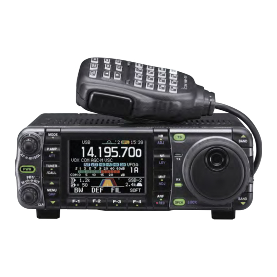
Icom IC-7000 Installing Manual
Lif port into the transceiver
Hide thumbs
Also See for IC-7000:
- Instruction manual (166 pages) ,
- Service manual (93 pages) ,
- Manual (34 pages)
Advertisement
Table of Contents
- 1 Installing a LIF Port into the IC-7000 Transceiver
- 2 LIF Port Installation
- 3 Dismantling the Transceiver
- 4 Connecting the RG174 Cable to the PCB
- 5 Routing the Cable and Reassembling of the Transceiver
- 6 Connection of the LIF Converter (RX-Only)
- 7 Setup of the CAT Interface
- 8 Omnirig Setup for the IC-7000 Series Transceivers
- Download this manual
Installing a LIF port into the IC-7000 transceiver
Intro
This document describes the procedure for installing an LIF (Low Intermediate
Frequency [9 – 18kHz]) port into the IC-7000 transceiver. This transceiver has a
high level of integration and already offers IF-DSP technology. Nevertheless,
connecting it to the MDSR has the advantages of improving audio clarity and the
reduction of hiss on low level signals. The noise reduction system of the IC-7000
is effective, but also makes the RX audio "boomy". The MDSR has a real-time
spectrum analyzer, which does not affect the audio quality. The demodulation
system of the IC-7000 works very similarly to the MDSR. But the MDSR has the
advantage that it utilizes the PC, which has a much more powerful processor.
This procedure requires a level of expertise to dismantle the transceiver and to
solder. Nonetheless, the installation is straightforward and should not cause any
difficulties for the experienced HAM operator.
It is important to unplug all connectors and power before working on any
transceiver. It is also important to be grounded to avoid static discharges.
Please note: no responsibility or liability will be taken by the author of this
document for any damage or malfunction caused by user modifications.
LIF port installation
Dismantling the Transceiver
The top cover of the radio must be removed. There are 8 screws that need
to be removed and then the lid will become loose; there are 4 screws on
the top cover and 2 on each side. Remove the lid carefully; the speaker
cable will still be connected to the circuit board. Unplug the speaker. In
order to extract the DSP assembly, two screws must be removed. When
taking the DSP assembly out, make sure that the gray audio cable does
not get pulled with the assembly.
An easy way to route the shielded RG-174 cable outside is to remove the
automatic antenna tuner plug. If this plug is required, an SMA connector
can be mounted on the left corner just above the ground screw. This
requires drilling a hole. To do this safely, all the PCBs on the top must be
removed, and all the holes that connect to the lower PCB must be covered
with masking tape to prevent metal shavings from falling onto the PCBs.
After drilling, all the metal shavings have to be wiped up with a slightly wet
cloth. Reassembling the unit can be difficult, especially the refitting of the
ribbon cables.
Advertisement
Table of Contents

Related Manuals for Icom IC-7000


Summary of Contents for Icom IC-7000
- Page 1 RX audio “boomy”. The MDSR has a real-time spectrum analyzer, which does not affect the audio quality. The demodulation system of the IC-7000 works very similarly to the MDSR. But the MDSR has the advantage that it utilizes the PC, which has a much more powerful processor.
- Page 2 Connecting the RG174 cable to the PCB The connection point is the 455kHz FL901 filter. This provides bidirectional (RX and TX) connectivity of the IF. If the transceiver is in RX mode the 455kHz IF can be extracted from this port and if it is in TX mode and a 455kHz signal is inserted, the radio will up-convert it and send it to the TX PA.
- Page 3 Setup of the CAT interface The MDSR software controls the transceiver via the CAT port. The connector cable CI-V is the Icom version of the interface cable that plugs into the back of the radio and the RS-232 port of the computer. There are also virtual RS-232 cables available that connect via the USB bus to the computer.
- Page 4 OmniRig Setup for the IC-7000 series transceivers To enter setup menu in MDSR-SA, select the tool icon at the bottom right and select “OmniRig Configuration & Status”, select the key icon “Configure OmniRig”. Only configure RIG 1. • Select the transceiver to be controlled from the drop down menu.
Need help?
Do you have a question about the IC-7000 and is the answer not in the manual?
Questions and answers