Table of Contents
Advertisement
Quick Links
Advertisement
Table of Contents

Related Manuals for Novatel WAAS G-III


Summary of Contents for Novatel WAAS G-III
- Page 1 WAAS G-III Reference Receiver USER MANUAL OM-20000137 Rev 1...
- Page 2 The information disclosed herein is the exclusive property of NovAtel Inc. and is not to be disclosed without the written consent of NovAtel Inc. No part of this publication may be reproduced or transmitted in any form or by any means including electronic storage, reproduction, execution or transmission without the prior written consent of NovAtel Inc.
-
Page 3: Table Of Contents
4.1 Entering Commands ........................36 4.1.1 Command Settings on Power-Up ..................36 4.1.2 Determining the Current Command Settings............... 38 4.1.3 Command Response ......................39 4.1.4 Command Prompt........................ 39 4.2 Functional Listing of Commands....................40 WAAS G-III Reference Receiver User Manual Rev 1... - Page 4 5.3 Functional Listing of Logs ......................91 5.4 Log Summary..........................92 5.5 Log Reference..........................92 5.5.1 AGCINFOB ...........................93 5.5.2 ALLSQMIB ..........................95 5.5.3 ALLSQMQB ..........................96 5.5.4 ALMANACB ..........................97 5.5.5 CARDSTATUSB........................98 5.5.6 CORRDATAB........................107 5.5.7 CORRLOCATIONB ......................108 5.5.8 ETHSTATUSB........................109 5.5.9 EXCEPTIONDATAB ......................110 WAAS G-III Reference Receiver User Manual Rev 1...
- Page 5 6.2 Download the Files ........................128 6.3 Decompress the Files ........................128 6.4 Update the G-III Reference Receiver Firmware................129 6.4.1 Serial Port Loading using WinLoad..................129 6.4.2 Ethernet Softload Protocol....................129 A Technical Specifications B Standards/References WAAS G-III Reference Receiver User Manual Rev 1...
- Page 6 SBAS Concept ..........................16 NovAtel G-III Reference Receiver ....................18 G-III Reference Receiver back panel ....................19 Typical Configuration........................22 LCD Status Display........................29 Status Display page 1 ........................30 Status Display page 2 ........................30 G-III Reference Receiver Dimensions..................135 WAAS G-III Reference Receiver User Manual Rev 1...
- Page 7 Channel Tracking Status ......................114 Channel Tracking Status ......................116 Parity Status ..........................118 Commands Included in RXCOMMANDSB Log ................. 121 SOFTLOADSTATUSB Status Values ..................124 TRAIM Status ..........................126 Performance Specifications ....................... 134 WAAS G-III Reference Receiver User Manual Rev 1...
- Page 8 Table of Contents Physical Specifications .......................135 Environmental Specifications .....................136 Port Specifications ........................136 Recommended External Frequency Reference Specifications ..........138 Channel Configuration ........................139 WAAS G-III Reference Receiver User Manual Rev 1...
-
Page 9: Customer Service
Customer Service Contact Information If you have any questions or concerns regarding your G-III Reference Receiver, contact NovAtel using one of the following methods: NovAtel GPS Hotline: 1-800-NOVATEL (U.S. and Canada) 1-403-295-4500 (International) Fax: 1-403-295-4501 E-mail: support@novatel.com Website: www.novatel.com Write: NovAtel Inc. -
Page 10: Notices
Changes or modifications to this equipment not expressly approved by NovAtel Inc. could result in violation of FCC and CE Marking rules and void the user’s authority to operate this equipment. -
Page 11: Primary And Secondary Lightning Protection
Figure 1: Primary and Secondary Lightning Protection Reference Description Primary Lightning Protection Device Secondary Lightning Protection Device External Antenna WAAS G-III Reference Receiver To Ground Grounding plate or grounding point at the building’s entrance WAAS G-III Reference Receiver User Manual Rev 1... - Page 12 Examples of country codes include: • National Electrical Code (NFPA 70) • Canada Canadian Electrical Code (CSA C22) • British Standards Institute (BSI 7671) WAAS G-III Reference Receiver User Manual Rev 1...
-
Page 13: Foreword
Foreword Scope The WAAS G-III Reference Receiver User Manual is written for users of the G-III Reference Receiver subsystem. The manual contains sufficient installation and operation information to allow you to effectively integrate and fully operate the unit. Additionally, each command used to configure the G-III Reference Receiver, as well as each log used to capture data, is described in detail, including the purpose, syntax, and structure of these messages. -
Page 14: Compliance With Gps Week Rollover
1023 ended on Saturday August 21, 1999 at 23:59:59. In accordance with the GPS system specifications document, NovAtel G-III Reference Receiver firmware resets the receiver's GPS week number back to zero. Users should be aware of this issue and keep in mind that there may be a compatibility issue when purchasing and using different makes of GNSS receivers. -
Page 15: Introduction
Chapter 1 Introduction The NovAtel G-III Reference Receiver is a high-performance receiver designed for installation as a core component of Satellite-Based Augmentation Systems (SBAS). This chapter provides information on the features and functionality of the G-III Reference Receiver and how it operates in the context of the SBAS system. -
Page 16: Features
Integrity data, differential corrections, time control and status The NovAtel G-III Reference Receiver provides GPS monitoring functionality as part of the Reference Stations in the SBAS network. Features To assist the Reference Stations in providing data with the necessary precision, the G-III Reference Receiver has the following features: •... -
Page 17: Cross-Correlation Detection
The results from TRAIM calculations are contained within the TIMESOLUTIONB log. For more information about this log, see Section 5.5.19, TIMESOLUTIONB on Page 125. WAAS G-III Reference Receiver User Manual Rev 1... -
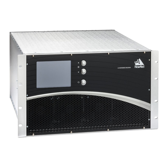
Page 18: Product Overview
Chapter 1 Introduction Product Overview The NovAtel G-III Reference Receiver unit consists of the following: • Standard enclosure for a 19-inch rack with built-in, forced air cooling • Liquid crystal display (LCD) to show receiver status • Input/output ports for power, antenna, frequency reference and general communications... -
Page 19: Enclosure
Table 1: Power Ports Label Description The power input port. Connects the G-III Reference Receiver to the 120/240 V power source. Chassis ground. Connects the G-III Reference Receiver to the mounting hardware ground. WAAS G-III Reference Receiver User Manual Rev 1... -
Page 20: Data Communication Ports
Shows the duplex status and collision activity on the Data port (J02) and the Monitor port (J03). Yellow Off = half-duplex connection (bottom LED) On = full-duplex connection Blinking = there are collisions WAAS G-III Reference Receiver User Manual Rev 1... -
Page 21: Radio Frequency Ports
Section 2.1, Typical Installation on Page 22 provides information about connecting to the ports, while Table 54, Port Specifications on Page 136 in Appendix A gives specifications on the connectors and signals provided at these ports. WAAS G-III Reference Receiver User Manual Rev 1... -
Page 22: Installation
• User-supplied data and RF cables The typical configuration of this equipment is shown in Figure 5. Figure 5: Typical Configuration 1 PPS DATA 1 PPS MAINT WAAS G-III Reference Receiver User Manual Rev 1... -
Page 23: Install The G-Iii Reference Receiver In A Rack
Connect the frequency reference to the 10 MHz IN (J06) TNC female connector on the rear panel of the G-III Reference Receiver. Table 54, Port Specifications on Page 136 provides technical port specifications. WAAS G-III Reference Receiver User Manual Rev 1... -
Page 24: Connect The Gnss Antenna
If you are using the Monitor port, connect a second RJ-45 Ethernet cable from the Monitor port (J03) on the G-III Reference Receiver to a computer or a port on the LAN switch. Refer to Table 54, Port Specifications on Page 136. WAAS G-III Reference Receiver User Manual Rev 1... -
Page 25: Optional Installation Steps
IP Address 192.168.0.10 Netmask 255.255.255.0 Gateway 0.0.0.0 Table 6: Monitor port default settings Setting Value Interface Name ETHB Virtual Port Identifier ICOM2 Ethernet Speed Auto Duplex Auto Port Polarity Auto Protocol Disabled Endpoint WAAS G-III Reference Receiver User Manual Rev 1... -
Page 26: Connect To The Maintenance Port
If you are configuring the Monitor port, use the ICOMCONFIG command to set the virtual COM port, UDP port and peer IP addresses. See Section 4.4.12, ICOMCONFIG on Page 57 for information about using the ICOMCONFIG command. WAAS G-III Reference Receiver User Manual Rev 1... -
Page 27: Access The 1 Pps Output
See Section 4.4.20, RFATTEN on Page 70 for information about setting the attenuator value. NovAtel recommends you use a 50 RF terminator on the RF1 OUT port when it is not being used. 2.2.6 Access the 10 MHz Output The 10MHz OUT port (J07) outputs the signal received from the 10 MHz IN port. -
Page 28: Operation
The valid commands used to control the operation and data logging of the G-III Reference Receiver are specified in Chapter 4. Chapter 5 provides details on the logs that contain data from the G-III Reference Receiver. WAAS G-III Reference Receiver User Manual Rev 1... -
Page 29: Status Display
The LCD display turns off when the buttons on the front panel have not been pressed for two minutes. To turn the display on, press any of the three front display buttons ( WAAS G-III Reference Receiver User Manual Rev 1... -
Page 30: Status Display
Monitor Port: <MonitorIP> Week: <WK> Sec: <Sec> Status: <TimeStat> Lat: <RxPosLatitude> Long: <RxPosLongitude> Height: <RxPosHeight> X: <RxPosX> Y: <RxPosY> Z: <RxPosZ> The following sections describe the information available on the Status display. WAAS G-III Reference Receiver User Manual Rev 1... -
Page 31: Rxstate Field Values
6 and module 1, the S field string appears as 6-1. If a component is not installed in the G-III Reference Receiver, the S field for that component appears blank. WAAS G-III Reference Receiver User Manual Rev 1... -
Page 32: Iomstatus Field Values
Orange External Comm External Communications Failed Stack Usage Warning Orange Stack Usage Warning Orange Temperature Temperature Failed Warning Orange Voltage Voltage Failed Warning Orange Fans Fans Failed Rx Config Failed Receiver Configuration WAAS G-III Reference Receiver User Manual Rev 1... -
Page 33: Dspcstatus Field Values
PLL not locked Warning Orange PLL Not Locked Temp Sensor Warning Orange Temperature Communication Voltage Sensor Warning Orange Voltage Communication FPGA Failed FPGA Warning Orange Temperature Temperature Failed Warning Orange Voltage Voltage Failed WAAS G-III Reference Receiver User Manual Rev 1... -
Page 34: Rfdcstatus Field Values
Text Color Condition Not Set The receiver time is not set. Coarse Orange The receiver time is set using broadcast navigation data. Fine Green The receiver time is set using range measurements. WAAS G-III Reference Receiver User Manual Rev 1... - Page 35 RxPosX, RxPosY and RxPosZ These fields show the X, Y and Z coordinates of the G-III Reference Receiver expressed in metres. If the receiver position is not set, these fields are blank. WAAS G-III Reference Receiver User Manual Rev 1...
-
Page 36: Commands
L2 auto L5 auto ANTENNAPOWER CHANCONFIG 18GPSALL8GEO L1geo 18 0.1 L1geo 19 0.1 L1geo 20 0.1 L1geo 21 0.1 CORRSPACING L1geo 22 0.1 L1geo 23 0.1 L1geo 24 0.1 L1geo 25 0.1 WAAS G-III Reference Receiver User Manual Rev 1... - Page 37 L5 95 2 RFATTEN RFIFTEMP TRACKMODE standard L5geo 26 i5 L5geo 27 i5 L5geo 28 i5 L5geo 29 i5 TRACKTYPE L5geo 30 i5 L5geo 31 i5 L5geo 32 i5 L5geo 33 i5 WAAS G-III Reference Receiver User Manual Rev 1...
-
Page 38: Determining The Current Command Settings
G-III Reference Receiver to output the CARDSTATUSB log. When the LOG command is entered the second time, the new parameter set does not overwrite the first, it exists in addition to the first set. WAAS G-III Reference Receiver User Manual Rev 1... -
Page 39: Command Response
(\r\n[), port name and end delimiter (]). For example: \r\n[ICOM1] In the front delimiter, \r is a CR character (0x0D) and \n is a NL character (0x0A). WAAS G-III Reference Receiver User Manual Rev 1... -
Page 40: Functional Listing Of Commands
Sets the signal acquisition, steady-state lock signal and cross-correlation THRESHOLD thresholds. TRACKMODE Changes the channel assignment method. TRACKTYPE Changes the type of tracking used for a specified channel. UNASSIGN Cancels a previously issued ASSIGN command. WAAS G-III Reference Receiver User Manual Rev 1... -
Page 41: Command Summary
Assigns a tracking channel to use to search ASSIGN [Doppler window]] for a satellite. CHANCONFIG config Changes the channel configuration of the CHANCONFIG receiver. CHANGESTATE state CHANGESTATE Changes the state of the receiver. WAAS G-III Reference Receiver User Manual Rev 1... - Page 42 SOFTLOADRESET SOFTLOADRESET Starts the firmware loading process. SOFTLOADSREC s-records Sends an S-Record format data block to a SOFTLOADSREC RAM buffer on the G-III Reference Receiver. SYSPROFILE SYSPROFILE Displays the system profile information. WAAS G-III Reference Receiver User Manual Rev 1...
- Page 43 TRACKTYPE specified channel. UNASSIGN svChan Cancels a previously issued ASSIGN UNASSIGN command. UNLOG [port] message Removes a specified log from logging UNLOG control. UNLOGALL [port] UNLOGALL Disables all logs from logging control. WAAS G-III Reference Receiver User Manual Rev 1...
-
Page 44: Command Reference
Acceptable Ports use the command. All three of the listed requirements must be met to use the command. If any of the three requirements are not met, the command will be rejected. WAAS G-III Reference Receiver User Manual Rev 1... -
Page 45: Agcmode
VARF modulus for manual mode. 35-262144 Ulong modulus This number has no effect when in auto mode. [Optional] a. The pulsewidth value must be less than or equal to the modulus value. WAAS G-III Reference Receiver User Manual Rev 1... -
Page 46: Antennapower
Valid States: Configuration Valid Modes: Normal Acceptable Ports: Data Syntax: ANTENNAPOWER flag Example: ANTENNAPOWER on Field Field Name Description Range Precision Enables (on) or disables (off) providing power to the flag antenna. WAAS G-III Reference Receiver User Manual Rev 1... -
Page 47: Assign
GPS PRNs may only be assigned to GPS SV channels, and SBAS PRNs may only be assigned to SBAS SV channels. Assigning a GPS PRN automatically dedicates channels to track all signal types for that PRN while SBAS signals must be assigned individually. WAAS G-III Reference Receiver User Manual Rev 1... - Page 48 This is a ± value. For example, enter 500 for ±500 Hz. a. If a Doppler is not specified, the receiver uses a default of 0 Hz. b. If a Doppler window is not specified, the receiver uses a default of 5000 Hz. WAAS G-III Reference Receiver User Manual Rev 1...
-
Page 49: Chanconfig
Receiver configuration Table 23: Channel Configuration Range Configuration Description 18 GPS channels tracking L1 C/A, L1 C, L2 C, L2 P(Y) and L5, 18GPSALL8GEO 8 L1 C/A SBAS and 8 L5 SBAS WAAS G-III Reference Receiver User Manual Rev 1... -
Page 50: Changestate
Use the CLEAREXCEPTIONDATA command to erase the data. Valid States: Configuration Valid Modes: Normal, Failed Acceptable Ports: Data Syntax: CHANGESTATE state Example: CHANGESTATE operational Field Field Name Description Range Precision operational state Receiver state maintenance WAAS G-III Reference Receiver User Manual Rev 1... -
Page 51: Clearexceptiondata
If there is exception data in non-volatile memory, you must clear the data using this command before the G-III Reference Receiver can change to the Operational state. Valid States: Configuration Valid Modes: Normal, Failed Acceptable Ports: Data Syntax: CLEAREXCEPTIONDATA Example: CLEAREXCEPTIONDATA WAAS G-III Reference Receiver User Manual Rev 1... -
Page 52: Corrspacing
The SV channel the discriminator spacing is applied to. 18-25 spacing Discriminator locations a. This range of SV channels tracking L1GEO is for the G-III 18GPSALL8GEO configuration. This range is different for other products. WAAS G-III Reference Receiver User Manual Rev 1... -
Page 53: Dllbw
Acceptable Ports: Data Syntax: DLLBW signal bw Example: DLLBW L1ca 0.1 DLLBW L5geo 0.2 Field Field Name Description Range Precision L1ca L1geo signal Signal type L2py L5gps L5geo DLL bandwidth (Hz) 0.001-0.5 Float WAAS G-III Reference Receiver User Manual Rev 1... -
Page 54: Ecutoff 10.0
Valid Modes: Normal Acceptable Ports: Data Syntax: ECUTOFF angle Example: ECUTOFF 10.0 Field Field Name Description Range Precision Elevation cut-off angle relative to horizon in degrees. angle 0 to 90 Double (decimal degrees) WAAS G-III Reference Receiver User Manual Rev 1... -
Page 55: Ethconfig
Data port. ethb corresponds to the Monitor port. b. If either the speed or duplex field is set to auto, both fields must be set to auto. WAAS G-III Reference Receiver User Manual Rev 1... -
Page 56: Fix
When a “FIX none” command is issued, the receiver will not have a position, nor will it calculate one. Time is also not calculated. The resolution of the input parameters is required for 1 mm position accuracy. WAAS G-III Reference Receiver User Manual Rev 1... -
Page 57: Icomconfig
Valid States: Configuration, Maintenance Valid Modes: Normal, Failed Acceptable Ports: Data, Maintenance Syntax: ICOMCONFIG port protocol [endpoint] [BindInterface] Example: ICOMCONFIG icom2 udp 255.255.255.255:3001 ETHB ICOMCONFIG icom1 udp :3000 ETHA ICOMCONFIG icom2 disabled WAAS G-III Reference Receiver User Manual Rev 1... - Page 58 This field is only optional if the protocol is set to disabled. The physical interface to which the ICOM port is ETHA bound. BindInterface ETHB This field is only optional if protocol is set to disabled. WAAS G-III Reference Receiver User Manual Rev 1...
-
Page 59: Ipconfig
This field defaults to 255.255.255.0 if not specified. The IP address of the gateway. Enter in the format: xxx.xxx.xxx.xxx gateway IPv4 address [Optional] This field defaults to 0.0.0.0 if not specified. a. APIPA IP address block 169.254.0.0/16 not supported. WAAS G-III Reference Receiver User Manual Rev 1... -
Page 60: Log
If the trigger condition is not specified, a default of once is used. Number of seconds between logs [Optional] period 1-1000 If the trigger condition is ontime, and the period is not specified, a default of 1 is used. WAAS G-III Reference Receiver User Manual Rev 1... -
Page 61: Message Type
Configuration state, the command is accepted and saved but the log will not begin to be output until the receiver is transitioned to the Operational state. WAAS G-III Reference Receiver User Manual Rev 1... -
Page 62: Nscode
0 0.5115 10230 3F10FF2610F479373A319A5C3167687F8D5C40B1FE0CD D9FFD176D100DE72CF7CD45408E169EA2BEEC4800C3A3BA752ABF598C96329698B53B56D7 08A386392DFBE0E66E4E80AAE9DBBB94BEAB3E2DE6608DA3EFBC808FA05E3C70459EDA597 9052F7E99147410990E8470CAFFDBB230AE0DC247167509B7FB38A1A6DE008E0E99C664D5 A6034B8C006A3B0AFA6B15F84BC4E522060C334F1B70FFDD754448E45B806F123F3385AE1 969A6E1A53A627982410F5EA013A2BE67111DB3D121A988DEE529405233EF76805872DEF3 3E15C95C152F409A56CE2086515677CF9EC9A84979CBFFBA25EC0818C6F2B1252B5FB6EF4 E87A5C2300B38E9E9AE2E461360B230258601E1A14825F02E3E6C3E7100CD4C9B99E0A4D9 BFF0A7929B013DB706BED9F2B765126075AC0B92B66F09347DDE5CA7151FF8A6DD1DB1B5A 04E755664C105A96D60F5097BC748B9AE90C7F15252ACE2063EFDAC36F7289A1D7B187CC4 20EB8D8D68A7BF36973D907A76A362D60CE5309838F61D9DEC2E963B1743F3EFEF26EECC1 D5CC55ED9CF4BB2F1E03A3AAB69951B0C86363E8905798E9739C10986FA81506080D308D0 DF9FCCBE2511D52EBAFE434A89290AFD7F358F7E4CC9BADFF32461E1E7D8000660463D6DC 93BDA318F2F84AB038D9E3EA5185646E202B4D789509D764802C3B20550EE8F3DADCF44D2 DEDB74DF07C6E0EB75DDBA91ACF12C3E3B1C5CDFDF0A849D75902E284762751283F78775B ADBA62FA1F8B4BFC9139D98E694979D973255AE75B9941EF54A74E304FC8A95CC6174C52A BB4E454B56897230D2E003BD6EDE95C177ED375B7A450B6B2EAC78333368CB582A78515AE DE63B979A1D4F5A328552BF93D444B328D693640D55D0225AF46FBA6DC73AB000665F2DFE B9044E6F8224853C127E27275567D4D30B1B61E756FE6B0502FEE64A2C1B353DFA16F46BE 039B8225DE5DC0AF8C827C3C1821B387328FDF6971ED7373285E07CD67905FBC34297E43F DCA399454215EEBBA85B64A3BCE9ABC06825D70FFC16AB6F0B814EB11941B1064E833691D B8592219CE30915F631D1B44DD7B5CAEE0AA2BB8C7E32722E7A81581FE65A7F0FA1D1F3EB 84CA775E670FF238E1E34DC51B58C1C29FA9B95A96A83129675FF33C7CDEE7395ADBF4DF1 03FD1578D709CD273D367712E7767126B915317160C52E6D57491EB1C3A5F01CF9465A414 43FD0C944433C31970D65DB5F0C01EAC24151E3E9F4673C8D15674D93D4C6D687E169A202 AE3E2B7C394E69D757956BE7FAF2612B927F4B5C203F749E946788F2AEB793F800A09AABD B0F62DBCF0DCBAC804C8FA93A17F0683B5A50BC6CEB02359015723526B2CAF4B9826D8B38 7EF29938BB7D132560CEAE021315E83DA0205B7B8538926D81101D62B9A08284E269A21BD 7F0C3BCAFE93B48AE09AE4A1A2A10385A5DE19722D249709BB1516FE592D88B0155227AFD 3F990D428A3062A34052504C6543B2B93471509A90721020B1D26A3686B32A7DEA8EBBD59 8FA5882DA3829B88BCA9678D195D0CC97E60D70CB20BCC290C9B144FE93D351C319BE8BED WAAS G-III Reference Receiver User Manual Rev 1... - Page 63 The following syntax has no effect on the receiver configuration. Instead, the command response contains the current NSCODE configuration of the specified signal type component. Alternate Syntax: NSCODE signal component Example: NSCODE L2C P <INFO: NSCODE L2C P 20 0.5115 BEEFBEE0 WAAS G-III Reference Receiver User Manual Rev 1...
-
Page 64: Nscode Allowable Parameters For Signal Types
L2CL 0-63 0.5115 27 (initial state) L5I GPS L5gps 0-63 10.23 10230 L5Q GPS L5gps 0-63 10.23 10230 L5I SBAS L5geo 0, 120-158 10.23 10230 L5Q SBAS L5geo 0, 120-158 10.23 10230 WAAS G-III Reference Receiver User Manual Rev 1... -
Page 65: Plldynamic
When this field set to FALSE, the fields TRUE setting marked as optional are not necessary and FALSE are ignored if specified. When this field set to TRUE, all of the fields are mandatory. WAAS G-III Reference Receiver User Manual Rev 1... - Page 66 If L2 P(Y) is configured for dynamic PLL with timethreshold a time threshold of less than 500 ms, the 20-100 000 command will be accepted but will have no effect on the PLL. [Optional] WAAS G-III Reference Receiver User Manual Rev 1...
-
Page 67: Pulseblanking
Specifies which frequency type to apply the frequency command to. Pulse Blanking threshold threshold 0-127 To turn off pulseblanking, set the threshold value to 0. exttime Pulse blanking extension time (μs) 0-10 WAAS G-III Reference Receiver User Manual Rev 1... -
Page 68: Reset
When the receiver is in the Operational state, the RESET command can be issued only from the Data port. Syntax: RESET Example: RESET A command response indicating that the RESET command was accepted successfully is output before the system resets. WAAS G-III Reference Receiver User Manual Rev 1... -
Page 69: Restore
NVM. After the Ethernet configuration is erased from NVM, the receiver resets. For a list of the default Ethernet configuration values, see Table 14 Factory Defaults for Commands on Page 36. Valid States: Configuration, Maintenance Valid Modes: Normal, Failed Acceptable Ports: Maintenance Syntax: RESTORE Example: RESTORE WAAS G-III Reference Receiver User Manual Rev 1... -
Page 70: Rfatten
This command changes the attenuation value on the software adjustable attenuator controlling the received RF signal. Valid States: Configuration, Operational Valid Modes: Normal Acceptable Ports: Data Syntax: RFATTEN setting Example: RFATTEN 20 Field Field Name Description Range Precision setting RF attenuator setting (dB) 0-30 WAAS G-III Reference Receiver User Manual Rev 1... -
Page 71: Rfiftemp
This command turns the RF/IF temperature control on or off. Valid States: Configuration Valid Modes: Normal Acceptable Ports: Data Syntax: RFIFTEMP setting Example: RFIFTEMP on Field Field Name Description Range Precision setting Enables or disables the RF/IF temperature control. WAAS G-III Reference Receiver User Manual Rev 1... -
Page 72: Saveports
To erase the saved configuration, use the RESTORE command (see Section 4.4.19 RESTORE on Page 69). Note that the RESTORE command will restart the receiver. Valid States: Configuration, Maintenance Valid Modes: Normal, Failed Acceptable Ports: Maintenance Syntax: SAVEPORTS Example: SAVEPORTS WAAS G-III Reference Receiver User Manual Rev 1... -
Page 73: Softloadcommit
This command verifies the uploaded firmware image and saves the image from the RAM buffer to flash memory. Valid States: Maintenance Valid Modes: Normal, Failed Acceptable Ports: Data Syntax: SOFTLOADCOMMIT Example SOFTLOADCOMMIT WAAS G-III Reference Receiver User Manual Rev 1... -
Page 74: Softloadfinalize
Chapter 4 Commands 4.4.24 SOFTLOADFINALIZE This command finalizes the firmware download by erasing the old firmware. Valid States: Maintenance Valid Modes: Normal, Failed Acceptable Ports: Data Syntax: SOFTLOADFINALIZE Example: SOFTLOADFINALIZE WAAS G-III Reference Receiver User Manual Rev 1... -
Page 75: Softloadreset
Commands Chapter 4 4.4.25 SOFTLOADRESET This command starts the firmware loading process. Valid States: Maintenance Valid Modes: Normal, Failed Acceptable Ports: Data Syntax: SOFTLOADRESET Example: SOFTLOADRESET WAAS G-III Reference Receiver User Manual Rev 1... -
Page 76: Softloadsrec
Valid States: Maintenance Valid Modes: Normal, Failed Acceptable Ports: Data Syntax: SOFTLOADSREC s-records Examples: SOFTLOADSREC S31D00000048000000000000000000000000000000000000000000000000 SOFTLOADSREC S0~T~APPS31D0000000006E0A6E10100000028000000280008000000001C E001001C03S31D0000001830000000582E5C009F5856AA2A5AD03501000000FEFFFFFF3C Field Field Name Description Range Precision String s-records S-Record Entries 2 to 8000 bytes WAAS G-III Reference Receiver User Manual Rev 1... -
Page 77: Sysprofile
The command response of the SYSPROFILE command ends with an empty line, i.e., CR+NL (0x0D,0x0A). Example: SYSPROFILE <INFO: SYSPROFILE:"MOPSW","AW3MM0000RN0000","May 23 2012","17:14:07","",5 SYSPROFILE:1,7,0,"DJV11100008","G3IOM-1.00","AW3IA0000RN0000", "AG3IB0000RB0000","","","May 23 2012","00:04:12","","","" SYSPROFILE:3,4,0,"DKF11180012","G3RFCC13-1.00","","","", "G3RFCCFPGA-7","","","","","" SYSPROFILE:4,4,1,"DKE11120011","G3RFDCG3-1.00","","","","","","", "","","" SYSPROFILE:2,2,0,"DJJ10460006","G3DSPC-1.00","AW3DA0000RN0000", "AG3DB0000RB0000","AG3NA0000RN0000","G3DSPCFPGA-10","May 23 2012", "00:05:18","","","" SYSPROFILE:2,2,1,"DJJ10460006","G3DSPC-1.00","AW3DA0000RN0000", "AG3DB0000RB0000","AG3NA0000RN00000","G3DSPCFPGA-10","May 23 2012", "00:05:18","","","" WAAS G-III Reference Receiver User Manual Rev 1... -
Page 78: Sysprofile Command Response Field Description
Max Length = 63 PBC SW Info Tag String Primary boot code information tag String Max Length = 19 SBC SW Info Tag String Secondary boot code information tag String Max Length = 19 WAAS G-III Reference Receiver User Manual Rev 1... -
Page 79: Threshold
For L1 C/A SBAS signal types, the range is from 18 to 25. For L5 SBAS signal types, the range is from 26 to 33. The threshold values must be specified per channel for SBAS signal types. WAAS G-III Reference Receiver User Manual Rev 1... -
Page 80: Trackmode
If a validated almanac is not available, all satellites will be searched for regardless of the channel assignment method selected. b. The only system this command applies to is GPS. If the system is not specified, it defaults to gps. WAAS G-III Reference Receiver User Manual Rev 1... -
Page 81: Tracktype
Specify q5i5 to use Q5 for tracking and I5 for data demodulation. a. This range of SV channels for tracking L5SBAS is for the G-III 18GPSALL8GEO configuration. This range will be different for other products. WAAS G-III Reference Receiver User Manual Rev 1... -
Page 82: Unassign
Field Name Description Range Precision 0-17 (GPS), svChan SV channel 18-33 (GEO) a. For L1 C/A SBAS, the range is 18 to 25. For L5 SBAS, the range is from 26 to 33. WAAS G-III Reference Receiver User Manual Rev 1... -
Page 83: Unlog
If a port is not specified, the command is applied to ICOM1 port the port the command was received on. ICOM2 [Optional] See Table 24 message Message type Message Type on Page 61 WAAS G-III Reference Receiver User Manual Rev 1... -
Page 84: Unlogall
Description Range Precision Communication port used to output the data. If a port is not specified, the command is applied ICOM1 port to the port the command was received on. ICOM2 [Optional] WAAS G-III Reference Receiver User Manual Rev 1... -
Page 85: Data Logs 5.1 Log Header
Message Length of the message in bytes. This does not Ushort length include the header nor the CRC Reserved 3 Reserved. Set to 0. Ushort Reserved 4 Reserved. Set to 0. Char WAAS G-III Reference Receiver User Manual Rev 1... -
Page 86: Iii Log Header Format
The GNSS week number count has been incremented by 1 every week and the field is modulo 1024 (i.e. set to 0 after 1023 weeks). The previous rollover should be accounted for in determination of GNSS week number by the user. WAAS G-III Reference Receiver User Manual Rev 1... -
Page 87: Log Triggers
A packed, fixed length (n) array of bytes. A variable length array of bytes that is null-terminated. The maximum byte length for String the field is shown in the row in the log table. WAAS G-III Reference Receiver User Manual Rev 1... -
Page 88: Commonly-Used Fields
Message Time Stamps All NovAtel format messages generated by the G-III Reference Receiver have a GNSS time stamp in the header. GNSS time is referenced to UTC with the zero point defined as midnight on the night of January 6, 1980 at 0:00 hours. -
Page 89: Gnss Time Status
FINE time status flag. The time status flag will never improve on FINE. The time will only be adjusted again to within ±1 microsecond if the range bias gets larger than ±250 milliseconds. WAAS G-III Reference Receiver User Manual Rev 1... - Page 90 ( ulCount-- != 0 ) ulTemp1 = ( ulCRC >> 8 ) & 0x00FFFFFFL; ulTemp2 = CRC32Value( ((int) ulCRC ^ *ucBuffer++ ) & 0xff ); ulCRC = ulTemp1 ^ ulTemp2; return( ulCRC ); WAAS G-III Reference Receiver User Manual Rev 1...
-
Page 91: Functional Listing Of Logs
Contains factory data for debug purposes. RXCOMMANDSB Contains the command parameters set by default or by command. SOFTLOADSTATUSB Shows the current status of the upgrade process. VERSIONB Contains the receiver version information. WAAS G-III Reference Receiver User Manual Rev 1... -
Page 92: Log Summary
Contains the receiver version information. Log Reference The following sections describe the logs available on the G-III Reference Receiver. Some logs have repeating data sets. This is represented by a double line between fields. WAAS G-III Reference Receiver User Manual Rev 1... -
Page 93: Agcinfob
DC offset A/D DC offset estimate (samples) Long H+80 Reserved Reserved Ulong H+84 Reserved Reserved Ulong H+88 18… Next RF deck, offset = H+4+(#previous freq*88) H + 4 + Variable 32-bit CRC (#freq*88) WAAS G-III Reference Receiver User Manual Rev 1... -
Page 94: Agc Status Word
0 = One of more bins filled 1 = All bins not filled Bins Empty: A flag identifying when all the bins are empty. 0 = Bins contain data 1 = All bins are empty 21-31 Reserved WAAS G-III Reference Receiver User Manual Rev 1... -
Page 95: Allsqmib
Signal channel for the tracked satellite Ulong #accumulations Number of accumulation values to follow. Ulong H+12 Asum I Accumulation value Long H+16 Variable Next channel data set, offset = H+4+#svobs(12+(4x#accumulations)) Variable 32-bit CRC Variable WAAS G-III Reference Receiver User Manual Rev 1... -
Page 96: Allsqmqb
Signal channel for the tracked satellite Ulong #accumulations Number of accumulation values to follow. Ulong H+12 Asum Q Accumulation value Long H+16 Variable Next channel data set, offset = H+4+#svobs(12+(4x#accumulations)) Variable 32-bit CRC Variable WAAS G-III Reference Receiver User Manual Rev 1... -
Page 97: Almanacb
Antispoofing flag where: antispoof 0=FALSE Enum H+120 1=TRUE 24… Next almanac data set, offset = H + 12 + (#previous msgs x 112) H + 12 + Variable 32-bit CRC (#entries x 112) WAAS G-III Reference Receiver User Manual Rev 1... -
Page 98: Cardstatusb
DSPC = slot ID of DSPC RFCC 1 (first RFCC values) = 4 Slot ID Ushort H+24 RFCC 2 (second RFCC values) = 4 RFCC 3 (third RFCC values) = 4 RFDC = 4 WAAS G-III Reference Receiver User Manual Rev 1... - Page 99 IOMaster = 1V8 Supply voltage (V) DSPC = 1V8 Supply voltage (V) RFCC 1 = 3V0A (V) Value 6 Float H+52 RFCC 2 = 2V5S5 (V) RFCC 3 = Reserved (0) RFDC = Reserved (0) WAAS G-III Reference Receiver User Manual Rev 1...
- Page 100 60) +4 H+20 + 0 = Okay Fan failed Ushort (#cards * 1 = Failed 60) +6 Next entry, offset = H+20 + (#cards * 60) + 4 + (#previous fans * 4) WAAS G-III Reference Receiver User Manual Rev 1...
-
Page 101: Iomaster Warning Status Word
Reserved (0) Reserved (0) Reserved (0) Temperature warning test failed Voltage warning test failed Fans warning test failed Reserved (0) Reserved (0) Reserved (0) Reserved (0) Reserved (0) 24 - 31 Reserved (0) WAAS G-III Reference Receiver User Manual Rev 1... -
Page 102: Dspc Warning Status Word
Table 38: RFCC Warning Status Word Nibble Bit # Description PLL lock test warning Reserved (0) Reserved (0) Reserved (0) Reserved (0) Reserved (0) Temperature monitor communications test warning Voltage monitor communications test warning WAAS G-III Reference Receiver User Manual Rev 1... -
Page 103: Rfdc Warning Status Word
Reserved (0) Temperature monitor communications test warning Voltage monitor communications test warning 8-11 Reserved (0) 12-15 Reserved (0) Temperature warning test failed Voltage warning test failed Reserved (0) Reserved (0) 20-31 Reserved (0) WAAS G-III Reference Receiver User Manual Rev 1... -
Page 104: Iomaster Error Status Word
Fans error test failed Receiver configuration failed 20 - 31 Reserved (0) Table 41: DSPC Error Status Word Nibble Bit # Description Reserved (0) Reserved (0) Reserved (0) Operational SW CRC integrity test failed WAAS G-III Reference Receiver User Manual Rev 1... -
Page 105: Rfcc Error Status Word
Reserved (0) 8 - 11 Reserved (0) Reserved (0) Reserved (0) Reserved (0) FPGA test failed Temperature error test failed Voltage error test failed Reserved (0) Reserved (0) 20 - 31 Reserved (0) WAAS G-III Reference Receiver User Manual Rev 1... -
Page 106: Rfdc Error Status Word
Table 43: RFDC Error Status Word Nibble Bit # Description Reserved (0) Reserved (0) 8-11 Reserved (0) 12-15 Reserved (0) Temperature error test failed Voltage error test failed Reserved (0) Reserved (0) 20-31 Reserved (0) WAAS G-III Reference Receiver User Manual Rev 1... -
Page 107: Corrdatab
Bin value Q Quadrature correlation value Long H+24 11… Next entry, offset = H+4+(#previous entries*(16 + # bins * 8)) H + 4 + variable 32-bit CRC (#entries * (16 + #bins * 8)) WAAS G-III Reference Receiver User Manual Rev 1... -
Page 108: Corrlocationb
Location of correlator Float H+12 6… Next entry, offset = H+4+(#previous entries*(8 + # locations * 4)) H + 4 + variable 32-bit CRC (#entries * (8 + # locations * 4)) WAAS G-III Reference Receiver User Manual Rev 1... -
Page 109: Ethstatusb
4 = 100Mbps/Full Duplex 5 = 100Mbps/Half Duplex Defaults to 0 if there is an error reading the value. Next entry, offset = H+4+(#previous entries*28) H + 4 + variable 32-bit CRC (#entries *28) WAAS G-III Reference Receiver User Manual Rev 1... -
Page 110: Exceptiondatab
Indicates if the exception data written in flash is corrupted. DataCorrupted BOOL H+16 TRUE = exception data is corrupted FALSE = exception data is not corrupted Exception Data The exception data for this card. Uchar[10240] 10240 H+20 32-bit CRC H+10260 WAAS G-III Reference Receiver User Manual Rev 1... -
Page 111: Factorydatab
G-III log header # cards Number of entries to follow Ulong Data Manufacturer's data Uchar[512] 4… Next entry, offset = H+4+(#previous cards*512) H + 4 + variable 32-bit CRC (#cards * 512) WAAS G-III Reference Receiver User Manual Rev 1... -
Page 112: Measurementdatab
Next data set, offset = H + 4 + (#previous obs x 64) H + 4 + variable 32-bit CRC (#obs x 64) a. The C/No reported in this log is computed from the tracking component only. WAAS G-III Reference Receiver User Manual Rev 1... -
Page 113: Tracking Type Data
6 = L2 P 7 = L2 Y 0 = false Non Standard Code 1 = true 0 = 0.1 chips Correlator Spacing 1 = 0.3 chips 2 = 1.0 chips 16-31 Reserved WAAS G-III Reference Receiver User Manual Rev 1... -
Page 114: Channel Tracking Status
0 = false PLL high BW used 1 = true 0 = false PLL dynamic changed 1 = true 0 = false Half cycle applied 1 = true 13-15 Reserved 16-31 Reserved WAAS G-III Reference Receiver User Manual Rev 1... -
Page 115: Rangeb
Channel status Ulong H+44 Tracking Status on Page 116) 13… Next data set, offset = H + 4 + (#previous obs x 44) H + 4 + Variable 32-bit CRC (#obs x 44) WAAS G-III Reference Receiver User Manual Rev 1... -
Page 116: Channel Tracking Status
0 = L1 0x00600000 Frequency 1 = L2 0 = C/A 0x03800000 Code Type 1 = P 2 = P codeless 0x7C000000 Reserved 0 = automatic 0x80000000 Channel assignment 1 = forced WAAS G-III Reference Receiver User Manual Rev 1... -
Page 117: Rawframedatab
Data Raw frame/subframe data H+24 Variable [variable] 32-bit CRC Variable a. Additional bytes of padding may be added to maintain 4 byte alignment. Padding bytes will be included in the #bytes count. WAAS G-III Reference Receiver User Manual Rev 1... -
Page 118: Parity Status
0 = Parity passed CRC status of L1C subframe 2 1 = Parity failed 0 = Parity passed CRC status of L1C subframe 3 1 = Parity failed 10-11 Reserved 12-15 Reserved WAAS G-III Reference Receiver User Manual Rev 1... -
Page 119: Rawgpssubframewpb
Number of subframes that had parity failures since #parity failures Ulong steady-state tracking Data Raw subframe data Hex[38] H+12 32-bit CRC H+52 a. An additional 2 bytes of padding is added to maintain 4 byte alignment WAAS G-III Reference Receiver User Manual Rev 1... -
Page 120: Rawwaasframewpb
Log header Channel Signal channel this frame was decoded on Ulong Satellite PRN tracked Ulong parity flag Parity failure flag Ulong Data Raw SBAS frame data Hex[32] H+12 32-bit CRC H+44 WAAS G-III Reference Receiver User Manual Rev 1... -
Page 121: Rxcommandsb
ASCII string variable 32 bit CRC variable Table 48: Commands Included in RXCOMMANDSB Log Commands AGCMODE ANTENNAPOWER ASSIGN CHANCONFIG CORRSPACING DLLBW ECUTOFF ETHCONFIG ICOMCONFIG IPCONFIG NSCODE PLLDYNAMIC PULSEBLANKING RFATTEN RFIFTEMP THRESHOLD TRACKMODE TRACKTYPE WAAS G-III Reference Receiver User Manual Rev 1... -
Page 122: Satposb
Health status from the almanac Ulong H+40 AlmElevation Float H+44 Elevation angle from the almanac (degrees) AlmAzimuth Float H+48 Azimuth angle from the almanac (degrees) AlmDop Geometric Doppler from the almanac (Hz) Float H+52 WAAS G-III Reference Receiver User Manual Rev 1... - Page 123 (#entries x 40) a. The Elevation will be set to -100 (default) if it is not computed. b. The Azimuth angle will be set to -1000 (default) if it is not computed. WAAS G-III Reference Receiver User Manual Rev 1...
-
Page 124: Softloadstatusb Status Values
The data cannot be loaded into the APP NVM block. BAD_IMAGE_CRC CRC of the received image has failed. IMAGE_OVERSIZE The received image is too large to store in flash. BAD_FLASH_ERASE Erasing of flash failed. BAD_FLASH_WRITE Writing of flash failed. WAAS G-III Reference Receiver User Manual Rev 1... -
Page 125: Timesolutionb
Satellite position from ephemeris Z coordinate (m) Double H+80 21… Next data set, offset = H + 36 + (#previous channels x 52) H + 36 + Variable 32-bit CRC (#channels x 52) WAAS G-III Reference Receiver User Manual Rev 1... -
Page 126: Traim Status
If bit 0 is set, one or more of bits 3-31 are set indicating the reason(s) the residual was excluded from the clock solution. Bit 0 is not set at the same time as bits 1 or 2. WAAS G-III Reference Receiver User Manual Rev 1... -
Page 127: Versionb
Secondary boot code information tag Char[20] 20 H+216 17… Next component, offset = H + 4 + (#previous comp x 232) H + 4 + Variable 32-bit CRC (#comp x 232) WAAS G-III Reference Receiver User Manual Rev 1... -
Page 128: Firmware Updates
4. Load the updates onto the G-III Reference Receiver Contact NovAtel The first step in updating the receiver is to contact NovAtel through any of the methods shown in Customer Service on Page 9. When you call, ensure that you have the version available. You can get the version by requesting the VERSIONB log. -
Page 129: Update The G-Iii Reference Receiver Firmware
COM port serial loading using WinLoad. It is not necessary to do both. 6.4.1 Serial Port Loading using WinLoad Follow these steps to load the G-III Reference Receiver using a computer and NovAtel's COTS program Winload. 1. Connect the MAINTENANCE port on the G-III Reference Receiver to a COM port on the computer using an RS-232 serial cable. - Page 130 11. Reset the G-III Reference Receiver to exit from the Maintenance state and restart the system with only a single firmware image by executing the following command. RESET 12. Capture a VERSIONB log to verify the firmware version has changed: LOG VERSIONB WAAS G-III Reference Receiver User Manual Rev 1...
- Page 131 6. Read the next line of the hex file. Ensure a carriage return is at the end of the line. 7. Use the contents of the line read to create a SOFTLOADSREC command. WAAS G-III Reference Receiver User Manual Rev 1...
- Page 132 # Open the G-III SW .hex file, read in one line at a time with open(SWFileName, 'r') as hexSWfile: for line in hexSWfile: if LoadingFailure == True: print "Loading Failure." break # Prepare the SREC line to be sent scmd = 'SOFTLOADSREC ' + line WAAS G-III Reference Receiver User Manual Rev 1...
- Page 133 += s.recv(2048) # Verify receiver accepts SRECORD if '<OK' in response: break except socket.timeout: LoadingFailure = True break except: LoadingFailure = True raise scmd = '' response = '' s.close() WAAS G-III Reference Receiver User Manual Rev 1...
-
Page 134: Performance Specifications
Pseudorange, ADR and SQM Once per second Time Once per second Re-acquisition 45 seconds C/No = 44 dB-Hz average L1 C/A, L2C, L5 L2 P(Y) 45 seconds C/No = 38 dB-Hz average WAAS G-III Reference Receiver User Manual Rev 1... -
Page 135: G-Iii Reference Receiver Dimensions
Appendix A Table 52: Physical Specifications PHYSICAL Size (WxHxD) 482.2 x 266.4 x 486.5 mm (with the 19” mounting brackets) Weight 12.6 kg (27.5 lb.) MECHANICAL DRAWINGS Figure 9: G-III Reference Receiver Dimensions WAAS G-III Reference Receiver User Manual Rev 1... -
Page 136: Environmental Specifications
Connector IEC C14 Voltage 120/240 VAC ~ 50/60 Hz Power Consumption < 150 Watts J02 DATA Connector RJ-45 Media 100BaseTX Standard IEEE 802.3 J03 MON Connector RJ-45 Media 100BaseTX Standard IEEE 802.3 WAAS G-III Reference Receiver User Manual Rev 1... - Page 137 ANTENNA INPUT (J11 RF1 IN) Connector TNC female RF Input Frequencies L1(1575.42 MHz), L2 (1227.6 MHz), L5 (1176.45 MHz) 11.7 VDC to 14.0 VDC Power <250 mA <100 mV (p-p) ripple WAAS G-III Reference Receiver User Manual Rev 1...
-
Page 138: Recommended External Frequency Reference Specifications
Output Waveform Sine wave -40 dBc Harmonics -80 dBc Spurious Phase Noise -120 dBc/Hz at 10 Hz -140 dBc/Hz at 100 Hz -150 dBc/Hz at 1 kHz WAAS G-III Reference Receiver User Manual Rev 1... -
Page 139: Channel Configuration
WAAS L5 SBAS Idle WAAS L5 SBAS Idle WAAS L5 SBAS Idle WAAS L5 SBAS Idle WAAS L5 SBAS Idle WAAS L5 SBAS Idle WAAS L5 SBAS Idle WAAS L5 SBAS Idle WAAS G-III Reference Receiver User Manual Rev 1... -
Page 140: B Standards/References
Appendix B Standards/References For copies of the GPS Interface Control Documents, go to: http://www.gps.gov/technical/icwg. This information is subject to change. WAAS G-III Reference Receiver User Manual Rev 1... - Page 141 SOFTLOADCOMMIT 73 bit synchronization 17 SOFTLOADFINALIZE 74 blanking 17 SOFTLOADRESET 75 blanking, digital pulse 67 SOFTLOADSREC 76 brightness, display 29 summary 41 THRESHOLD 79 tracking control 40 CARDSTATUSB log 98 TRACKMODE 80 WAAS G-III Reference Receiver User Manual Rev 1...
- Page 142 Customer Service 9 external clock, input 23 cut-off angle, setting 54 external frequency reference cyclic redundancy check (CRC), algorithm 90 connect 23 specifications 138 data communication, connect 24 Data port 20 factory defaults 36 WAAS G-III Reference Receiver User Manual Rev 1...
- Page 143 91 configure 26 MEASUREMENTDATAB 112 overview 20 message type 61 specifications 136 period 60 RANGEB 115 configure 26 RAWFRAMEDATAB 117 default settings 25 RAWGPSSUBFRAMEWPB 119 overview 20 RAWWAASFRAMEWPB 120 specifications 136 WAAS G-III Reference Receiver User Manual Rev 1...
- Page 144 135 regulatory notices 10 PLL, dynamic tracking 65 requirements, antenna 24 PLLDYNAMIC command 65 reset 68 port polarity, Ethernet 55 RESET command 68 ports response messages 1 PPS In 21 WAAS G-III Reference Receiver User Manual Rev 1...
- Page 145 128 specifications version, receiver software 127 environmental 136 VERSIONB log 127 external frequency reference 138 voltage 136 performance 134 physical 135 ports 136 wide-area reference station 15 start up command settings 36 WAAS G-III Reference Receiver User Manual Rev 1...
- Page 146 Recyclable Printed in Canada on recycled paper OM-20000137 Rev 1 March 2013...
Need help?
Do you have a question about the WAAS G-III and is the answer not in the manual?
Questions and answers