Table of Contents
Advertisement
Quick Links
Advertisement
Chapters
Table of Contents

Related Manuals for Novatel SPAN CPT7


Summary of Contents for Novatel SPAN CPT7
- Page 1 SPAN CPT7 Installation and Operation User Manual OM-20000179 v3A January 2019...
- Page 2 Information in this document is subject to change without notice and does not represent a com- mitment on the part of NovAtel Inc. The software described in this document is furnished under a licence agreement or non-disclosure agreement. The software may be used or copied only in accordance with the terms of the agreement.
-
Page 3: Table Of Contents
2.8 Mounting the GNSS Antenna 2.8.1 Antenna LNA Power 2.9 Mount the SPAN CPT7 2.9.1 Securing the SPAN CPT7 2.9.2 Secure the SPAN CPT7 Using the Adapter Plate 2.10 Connect the SPAN CPT7 to Data Communication Equipment 2.10.1 Serial Ports 2.10.2 USB Ports 2.10.3 Ethernet Port... - Page 4 4.5 Synchronizing External Equipment 4.5.1 Configuring an Input Strobe 4.6 Adding Timed Sensor Triggers 4.6.1 Configuring the Hardware 4.6.2 Configuring the Software 4.6.3 Using Timed Event Pulses 4.6.4 Recording Incoming Sensor Events SPAN CPT7 Installation and Operation User Manual v3A...
- Page 5 7.5 NovAtel Messages Over CAN 7.6 Configuring OEM7 Receivers to Use OEM6 CAN Settings 7.6.1 Configuration on OEM6 7.6.2 Configuration on OEM7 Chapter 8 Built-In Status Tests 8.1 Receiver Status Word 8.2 RXSTATUSEVENT Log SPAN CPT7 Installation and Operation User Manual v3A...
- Page 6 A.4 SPAN CPT7 Data Communication Specifications A.5 SPAN CPT7 Strobe Specifications A.6 SPAN CPT7 Connectors A.7 SPAN CPT7 I/O1 Cable A.7.1 Custom Cable Recommendations A.8 SPAN CPT7 I/O2 Cable A.8.1 Custom Cable Recommendations SPAN CPT7 Installation and Operation User Manual v3A...
- Page 7 APPENDIX B Accessories and Replacement Parts APPENDIX C Frequently Asked Questions APPENDIX D Importance of Antenna Selection SPAN CPT7 Installation and Operation User Manual v3A...
- Page 8 Figure 2: Typical Installation of a SPAN CPT7 System Figure 3: SPAN CPT7 Adapter Plate Figure 4: Offset from the SPAN CPT7 to the SPAN-CPT Figure 5: Offset from the SPAN CPT7 to the SPAN-IGM-S1 Figure 6: Fuse for PwrPak7 Power Supply...
- Page 9 Figure 42: Fischer Core 16 Pin Connector Figure 43: SPAN CPT7 I/O1 Cable Figure 44: SPAN CPT7 I/O2 Cable Figure 45: Plot of Good and Poor Antenna Phase Center Variation over Elevation Angle 0- 90° SPAN CPT7 Installation and Operation User Manual v3A...
- Page 10 Table 19: SPAN CPT7 IMU Performance Table 20: SPAN CPT7 Environmental Specifications Table 21: SPAN CPT7 Power Requirements Table 22: SPAN CPT7 RF Input/LNA Power Output Table 23: Data Communications Interfaces Table 24: SPAN CPT7 Strobes Description Table 25: SPAN CPT7 Strobe Electrical Specifications...
-
Page 11: Span Cpt7 Notices
Innovation, Science and Economic Development (ISED) Canada SPAN CPT7 Class B digital device complies with Canadian ICES-003. SPAN CPT7 appareils numérique de la classe B sont conforme à la norme NMB-003 du Canada. This device complies with ISED license-exempt RSS-GEN and RSS-247. Operation is subject to... - Page 12 60°C, installation in a RESTRICTED ACCESS LOCATION is not required. WEEE If you purchased your SPAN CPT7 in Europe, please return it to your dealer or supplier at the end of life. The objectives of the European Community's environment policy are, in particular, to preserve, protect and improve the quality of the environment, protect human health and utilise natural resources prudently and rationally.
- Page 13 SPAN CPT7 Notices REACH SPAN CPT7 receivers are in compliance with Regulation (EC) No 1907/2006 OF THE EUROPEAN PARLIAMENT AND THE COUNCIL of 18 December 2006 concerning the Registration, Evaluation, Authorization and Restriction of Chemicals (REACH). The Candidate List of Substances of Very High Concern (SVHC) published by the European Chemical Agency (ECHA) is available at https://echa.europa.eu/candidate-list-table.
- Page 14 6. The primary and secondary lightning protections should be as close to the building's entrance as possible. Where feasible, mount onto the grounding plate itself (refer to the figure below). SPAN CPT7 Installation and Operation User Manual v3A...
- Page 15 Where applicable, follow the electrical codes for the country of installation. Examples of country codes include: USA National Electrical Code (NFPA 70) Canada Canadian Electrical Code (CSA C22.1) UK British Standard (BS7671) SPAN CPT7 Installation and Operation User Manual v3A...
- Page 16 A caution that actions, operation or configuration may lead to incorrect or improper use of the hardware. A warning that actions, operation or configuration may result in regulatory non- compliance, safety issues or equipment damage. SPAN CPT7 Installation and Operation User Manual v3A...
-
Page 17: Customer Support
If you are having a hardware problem, send a list of the troubleshooting steps taken and the res- ults. Contact Information Log a support request with NovAtel Customer Support using one of the following methods: SPAN CPT7 Installation and Operation User Manual v3A... - Page 18 Log a Case and Search Knowledge: Website: www.novatel.com/support Log a Case, Search Knowledge and View Your Case History: (login access required) Web Portal: https://novatelsupport.force.com/community/login E-mail: support@novatel.com Telephone: U.S. and Canada: 1-800-NOVATEL (1-800-668-2835) International: +1-403-295-4900 SPAN CPT7 Installation and Operation User Manual v3A...
-
Page 19: Chapter 1 Span Cpt7 Overview
GNSS+INS solution has the advantage of the absolute accuracy available from GNSS and the continuity of INS through traditionally difficult GNSS conditions. NovAtel's SPAN CPT7 is a scalable, high precision GNSS+INS receiver in a lightweight, compact, environmentally protective enclosure. The SPAN CPT7 provides the following features:... -
Page 20: Fundamentals Of Gnss+Ins
Chapter 1 SPAN CPT7 Overview SPAN CPT7 technical specifications are provided in SPAN CPT7 Technical Specifications on page 144. 1.1 Fundamentals of GNSS+INS GNSS positioning observes range measurements from orbiting GNSS satellites. From these observations, the receiver can compute position and velocity with high accuracy. NovAtel GNSS positioning systems are highly accurate positioning tools. -
Page 21: Chapter 2 Span Cpt7 Installation
SPAN CPT7 before using Ethernet. When the SPAN CPT7 is installed in a permanent location, such as in a building, it should be protected by a lightning protection device according to local building codes. See Light- ning Protection Installation and Grounding Procedure on page 14. -
Page 22: Selecting A Gnss Antenna
European Union’s Restriction of Haz- ardous Substances (RoHS) and Waste Electrical and Electronic Equipment (WEEE). If a non-NovAtel GNSS antenna is chosen, a typical antenna LNA gain between 26 dB to 30 dB is recommended in a rover station application. -
Page 23: Choosing A Coaxial Cable
2.5 m and 5 m antenna cable with an SMA connector on one end and a TNC connector on the other (NovAtel part numbers 60723177 and 60723178) The SPAN CPT7 requires cables with an SMA connector on the receiver side or an SMA to TNC adapter. -
Page 24: Span Cpt7 Installation Overview
Do not connect a power supply to both ports. 2.7 SPAN CPT7 Installation Overview A SPAN CPT7 system consists of a SPAN CPT7, a GNSS antenna, power and a communication link (if your application requires real time differential operation). The following diagram shows a typical SPAN CPT7 installation. - Page 25 Connect the secondary GNSS antenna to the RF2 port on the SPAN CPT7. The SPAN CPT7 supplies +5 VDC (200 mA maximum) to the antenna LNA through the center conductor of the antenna cable. See Antenna LNA Power on the next page for more inform- ation.
-
Page 26: Mounting The Gnss Antenna
2.9 Mount the SPAN CPT7 Mount the SPAN CPT7 in a fixed location where the distance from the SPAN CPT7 to the phase center of the GNSS antennas is constant. Ensure that the orientation with respect to the vehicle and antennas is also constant. -
Page 27: Securing The Span Cpt7
1. Place the SPAN CPT7 on the Adapter Plate and align the mounting hole on the SPAN CPT7 with the threaded holes in the Adapter Plate. 2. Secure the SPAN CPT7 to the Adapter Plate using the four screws (#6 - 32) included with the SPAN CPT7 Installation and Operation User Manual v3A... - Page 28 4. If the SPAN CPT7 is replacing a SPAN-CPT or SPAN-IGM-S1, see Figure 4: Offset from the SPAN CPT7 to the SPAN-CPT on page 30 or Figure 5: Offset from the SPAN CPT7 to the SPAN- IGM-S1 on page 31 for the offset of the center of navigation of the previous system to the center of navigation of the SPAN CPT7.
- Page 29 Chapter 2 SPAN CPT7 Installation Figure 3: SPAN CPT7 Adapter Plate SPAN CPT7 Installation and Operation User Manual v3A...
- Page 30 Figure 4: Offset from the SPAN CPT7 to the SPAN-CPT Dimensions are in mm. The axis marking on the SPAN CPT7 indicates the orientation of the X, Y and Z axis only. It does not indicate the center of navigation. For the location of the center of navigation, refer to Figure 41: SPAN CPT7 Center of Navigation on page 150.
-
Page 31: Connect The Span Cpt7 To Data Communication Equipment
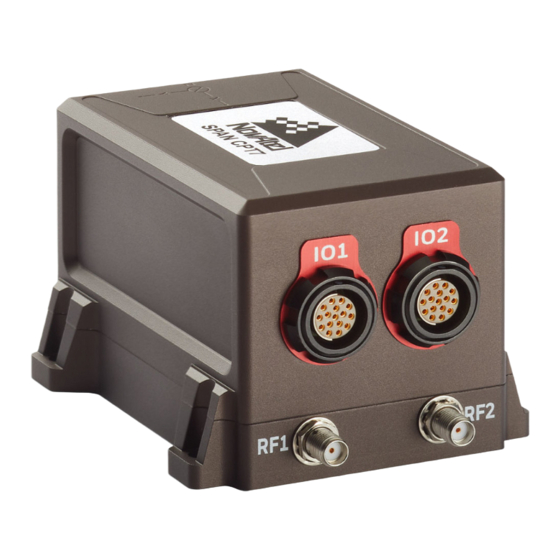
2.10.1 Serial Ports The SPAN CPT7 has two serial ports: COM1 and COM2. COM1 uses RS-232 protocol and is avail- able on the IO2 port. COM2 uses RS-422 protocol and is available on the IO1 port. Refer to SPAN CPT7 Connectors on page 155 for the pin out of these connectors. -
Page 32: Usb Ports
1. Connect the SPAN CPT7 I/O2 SPAN cable, or a custom made cable, to the IO2 connector. 2. Connect the USB connector on the SPAN CPT7 I/O2 SPAN cable to a USB port on the com- puter or other data communication device. -
Page 33: Connect I/O Signals To The Span Cpt7
Chapter 2 SPAN CPT7 Installation The SPAN CPT7 CAN bus port is unterminated. If the SPAN CPT7 is at the end of the bus, then the connecting cable must have 120 ohms integrated into the cable between CANH and CANL in close proximity to the I/O2 connector. -
Page 34: Fuse For The Power Supply
When a vehicle engine is star- ted, the voltage on the starter battery can dip below the SPAN CPT7 minimum voltage or cut-out to ancillary equipment causing the receiver to lose lock and calibration settings. -
Page 35: Check That The Span Cpt7 Is Operating
Figure 7: Dedicated Battery for the SPAN CPT7 2.13 Check that the SPAN CPT7 is Operating After the SPAN CPT7 is installed, powered up and connected to a GNSS antenna, use the fol- lowing procedure to ensure the receiver is operating. -
Page 36: Chapter 3 Oem7 Receiver Operation
Chapter 3 OEM7 Receiver Operation Before operating the receiver for the first time, use the installation instructions in SPAN CPT7 Installation on page 21. The following instructions are based on a configuration similar to the fol- lowing figure. Figure 8: Basic SPAN CPT7 Connection Interfaces (example) The figure above does not show all necessary hardware. -
Page 37: Usb Communications
(for example, NovAtel Connect). The NovAtel USB drivers assign COM port numbers sequentially following any existing ports on the computer. For example, if a com- puter has COM1 and COM2 ports, the NovAtel USB drivers assign COM3 to USB1, COM4 to USB2 and COM5 to USB3. -
Page 38: Table 3: Serial Ports Supported
To change the settings on a COM port, use the SERIALCONFIG command. For example: To change the data rate of COM2 to 115200, enter: SERIALCONFIG COM2 115200 To change the data rate of COM1 to 57600 and enable even parity, enter: SERIALCONFIG COM1 57600 E SPAN CPT7 Installation and Operation User Manual v3A... -
Page 39: Ethernet Communications
Use any standard communications software package that emulates a terminal to establish bidirectional communications with the receiver. Examples include NovAtel Connect and PuTTY. All data is sent as raw 8-bit binary or ASCII characters. -
Page 40: Can Bus Communications
3.1.5 CAN Bus Communications The OEM7 receiver supports J1939 and NMEA2000 CAN protocols. The SPAN CPT7 has one CAN port. This CAN port supports data rates up to 1 Mbps. Proper bus termination is required. Refer to CAN Bus on page 111 for detailed instructions. -
Page 41: Transmitting And Receiving Corrections
RXSTATUSEVENTA log ONNEW on all ports. See RXSTATUSEVENT Log on page 118 for more details. 2. If NovAtel Connect is unable to locate the OEM7 receiver, use a different COM port to communicate with the receiver. When communication has been established, issue a FRESET STANDARD command. - Page 42 To receive corrections, a data link between the base station and the rover station is required. The base and rover stations can both be NovAtel receivers, however NovAtel receivers will work with some other brands. Contact Customer Support for further details (refer to Customer Sup- port on page 17 for details).
-
Page 43: Defining Antenna And Base Antenna
120 saveconfig (optional) RTCM V3 with GLONASS serialconfig com2 19200 N 8 1 N on interfacemode com2 none rtcmv3 off fix position lat lon hgt (enter your own lat, lon, hgt) SPAN CPT7 Installation and Operation User Manual v3A... -
Page 44: Rover Station Configuration
Corrections on page 41. This requires using the INTERFACEMODE command to dedicate one direction of a serial port to one message type only. When the INTERFACEMODE command is used to change the mode from the NOVATEL default, the NovAtel format messages can no longer be used. -
Page 45: Glide
51.11358042 -114.04358013 1059.4105 log com2 rtcm1004b ontime 2 1. Interface mode must be set to NOVATEL for the receiver to issue logs with an A or B suffix. 2. Using the receiver in NOVATEL mode consumes more CPU bandwidth than using the native differential messages as shown in Base Station Configuration on page 43. -
Page 46: Pdp And Glide Configurations
3.5.1 Maintain When the receiver transitions to a different positioning mode, it maintains the position offset cal- culated to limit a potential real position jump. The receiver continues to apply the position offset SPAN CPT7 Installation and Operation User Manual v3A... -
Page 47: Transition
RTK positions at a default rate of 0.005 m/s or the time specified in the STEADYLINE command. Figure 13: STEADYLINE Prefer Accuracy SPAN CPT7 Installation and Operation User Manual v3A... -
Page 48: Ual
C The solution accuracy moves back within the operational limit. The position type changes to OPERATIONAL. The STEADYLINE mode remains in Prefer Accuracy mode. D The solution offset is removed. The STEADYLINE mode changes from Prefer Accuracy to Maintain. SPAN CPT7 Installation and Operation User Manual v3A... -
Page 49: Enabling Sbas Positioning
NovAtel L-Band-capable antennas). For more information on L-Band positioning, refer to: NovAtel Application Notes: APN-061: NovAtel CORRECT with PPP using TerraStar Corrections or APN-062 NovAtel CORRECT with Veripos (service dependent) available from www.nova- tel.com/support/search/items/Application%20Note OEM7 Commands and Logs Reference Manual... -
Page 50: Terrastar Subscriptions
A subscription is required to use TerraStar service for land, airborne and near shore applic- ations. Near shore applications are defined as vessels operating within 10 km of shore. To obtain a subscription, contact your local NovAtel sales representative or visit www.nova- tel.com/products/terrastar-gnss-corrections. -
Page 51: Veripos Subscriptions
NovAtel sales representative or visit www.novatel.com/products/terrastar- gnss-corrections/. The NovAtel Product Serial Number (PSN) is needed to obtain a subscription. The PSN is available from the VERSION log. RTK ASSIST is available as soon as the rover receiver has at least one valid RTK solution and has received the RTK ASSIST correction data. -
Page 52: Transferring Time Between Receivers
Coarse Time Each subframe contains the transmit time of the next subframe in seconds of GPS Time of Week (TOW). After the first subframe is collected and decoded by the receiver, an approximate SPAN CPT7 Installation and Operation User Manual v3A... -
Page 53: Procedures To Transfer Time
Figure 16: Transfer COARSE Time from Fine Clock to Cold Clock Receiver on the next page. Configure both ports to the same baud rate and handshaking configurations. 2. Issue the following command to the fine clock receiver: SPAN CPT7 Installation and Operation User Manual v3A... - Page 54 TIMESYNC log has arrived within 200 ms of the last 1PPS event. If so, it sets the cold clock receiver clock to the time of the fine clock receiver. See Figure 19: 1 PPS Alignment on page 56. SPAN CPT7 Installation and Operation User Manual v3A...
- Page 55 1 PPS to the incoming 1 PPS of the fine clock receiver. It does not adjust the one second TOW counter or the receiver’s week number. This procedure is used to make small cor- rections to the warm clock receiver’s clock. SPAN CPT7 Installation and Operation User Manual v3A...
- Page 56 Receiver on the previous page and Figure 18: Transfer FINE Time from Fine Clock to Warm Clock Receiver above are for the transfer of time. If a position is needed, the receiver must be tracking satellites and must have a valid almanac. SPAN CPT7 Installation and Operation User Manual v3A...
-
Page 57: Interference Toolkit
Disable/Enable Detection on page 59 for instructions. Detected interference can be viewed and different tracking modes with possible additional filters can be applied to mitigate the inter- ference using NovAtel Connect. Detected interference details can also be logged and analyzed using the command line interface. - Page 58 The Statistical Analysis Detection is designed as a sensitive detection tool. Out of band mit- igation does not impose much penalty when enabled and it brings awareness to unintentional interferences next to GNSS operations. SPAN CPT7 Installation and Operation User Manual v3A...
-
Page 59: Disable/Enable Detection
The spectrum can then be viewed by plot- ting the PSD samples in the ITPSDFINAL log. NovAtel Connect can also be used to view the spectrum. See Monitoring Signals Using NovAtel Connect on the next page. -
Page 60: Monitoring Signals Using Novatel Connect
Due to the high volume of data, a higher bandwidth medium, such as USB or Ethernet, is recommended when monitoring signals using the Interference Toolkit. Start NovAtel Connect and open a connection to the OEM7 receiver. Scroll down to the Interference Toolkit and double click on the Interference Toolkit tile. -
Page 61: Remove Interference Signals
GNSS signals. HDR mode works well against wide band and out-of-band interferers. HDR mode can be combined with bandpass and notch filters, but does draw more power. SPAN CPT7 Installation and Operation User Manual v3A... - Page 62 To configure a bandpass filter, use the ITPROGFILTCONFIG command or the ITBANDPASSCONFIG command. A bandpass filter can also be configured using NovAtel Con- nect. Example of a Notch Filter The following example shows interference at 1750 in the signal band.
- Page 63 Summarizes the filter configuration for each frequency and indicates ITFILTTABLE which bandpass or notch filters are enabled and configured. ITPROGFILTBANK Provides the allowable programmable filter configurations. Provides the power spectral density information of the specified signal ITPSDFINAL √ path. SPAN CPT7 Installation and Operation User Manual v3A...
-
Page 64: Logging And Retrieving Data Overview
Data can be collected using NovAtel Connect or NovAtel Web User Interface. Refer to the Help available from within NovAtel Connect for comprehensive logging instructions. Refer to the online OEM7 documentation (docs.novatel.com/OEM7) for information about logging using... -
Page 65: Additional Features And Information
OEM7 receivers have inputs and outputs, referred to as strobes, that provide status and syn- chronization signals. Not all strobes are provided on all receivers. For detailed information about OEM7 receiver strobes, see: SPAN CPT7 Strobe Specifications on page 154 SPAN CPT7 Installation and Operation User Manual v3A... -
Page 66: Chapter 4 Span Operation
Before operating your SPAN system, ensure that you have followed the installation and setup instructions in SPAN CPT7 Installation on page 21. You can use the NovAtel Connect software to configure receiver settings and to monitor data in real-time, between a rover SPAN system and base station. -
Page 67: The Imu Body Frame
SPAN CPT7. Refer to SPAN CPT7 Mechanical Specifications on page 148 for illustrations of the IMU Body frame axes. The axis marking on the SPAN CPT7 indicates the orientation of the X, Y and Z axis only. It does not indicate the center of navigation. For the location of the center of navigation, refer to Figure 41: SPAN CPT7 Center of Navigation on page 150. -
Page 68: The Vehicle Frame
The orientation of the IMU relative to the forward direction of the vehicle is also needed to con- vert the velocity and attitude changes sensed by the IMU into the actual motion of the vehicle. SPAN CPT7 Installation and Operation User Manual v3A... -
Page 69: Translational Offsets
The X, Y and Z axes of the IMU Body frame are also indicated on the mechanical draw- ings of the IMUs in the SPAN CPT7 Mechanical Specifications on page 148. Figure 23: IMU to Antenna Translation Offset below shows an example of the translational off- sets from the IMU to a GNSS antenna. -
Page 70: Rotational Offsets
An example is the vehicle frame, where Z is always considered to be upwards, Y forward through the direction of travel, and X to the right. Rotational Offsets - Example Consider an IMU installed in the following way: SPAN CPT7 Installation and Operation User Manual v3A... - Page 71 Observe that if a negative 90 degree rotation is performed about the new IMU X axis, the rotated IMU Y axis is now collinear with the Vehicle Y axis, and the rotated IMU Z axis is also col- linear with the Vehicle Z axis. SPAN CPT7 Installation and Operation User Manual v3A...
-
Page 72: Software Configuration
SPAN enabled models and allow for simple configuration rather than sending many discreet commands. The plus models are restricted by model and enable additional per- formance or functionality, such as dead reckoning or heave. SPAN CPT7 Installation and Operation User Manual v3A... -
Page 73: Table 4: Oem7 Ins Profiles
To use an INS Profile, send the SETINSPROFILE command at startup (or save to NVM) to activ- ate the mode. For example: SETINSPROFILE LAND_BASIC The currently selected profile option is available in the INSCONFIG log. SPAN CPT7 Installation and Operation User Manual v3A... -
Page 74: Span Configuration For Span Cpt7
SETALIGNMENTVEL velocity Configure SPAN Manually Follow these steps to enable INS as part of the SPAN CPT7 system using software commands: A GNSS antenna with a clear view of the sky must be connected and tracking satellites for operation. SPAN CPT7 Installation and Operation User Manual v3A... - Page 75 The offset between the antenna phase center and the IMU axis must remain constant and be known accurately (m). The X, Y and Z directions are clearly marked on the SPAN CPT7 enclosure. The SETINSTRANSLATION parameters are (where the standard deviation fields...
- Page 76 Routine on page 84. SPAN Configuration with NovAtel Connect NovAtel Connect provides a wizard that takes you through the steps required to configure a SPAN system. For information about using the SPAN Configuration wizard in NovAtel Connect, refer to the help file available within NovAtel Connect.
-
Page 77: Real-Time Operation
INS_ SOLUTION_ This may be due to multipath or limited satellite visibility. The inertial FREE filter has rejected the GNSS position and is waiting for the solution quality to improve. SPAN CPT7 Installation and Operation User Manual v3A... -
Page 78: System Start-Up And Alignment Techniques
COMPLETE. The system transitions to navigation mode. 9. The solution is refined using updates from GNSS. Once the system is operating within spe- cifications and after some vehicle movement, the INS Status field changes to INS_ SPAN CPT7 Installation and Operation User Manual v3A... - Page 79 INS Status field in the INS logs. Dual Antenna Alignment SPAN can also use heading information available from a NovAtel Dual Antenna ALIGN solution to rapidly perform an alignment. Refer to SPAN with Dual Antenna on page 99 for details.
-
Page 80: Ins Seed / Fast Ins Initialization
10 degrees in roll and pitch If a valid error model is present in the seed data from NVM, this will always be used, even if the system is not stationary or exceeded the movement thresholds. SPAN CPT7 Installation and Operation User Manual v3A... - Page 81 INS solution data from NVM, bits 26-28 will be set to 101 NVM Seed Status: Bits 29-31 These bits indicate the current status of the seeding process at start-up, as described in the table below: SPAN CPT7 Installation and Operation User Manual v3A...
-
Page 82: Navigation Mode
The INS solution is available in the INS-specific logs with either a standard or short header. Other parameters are available in the logs shown in Table 7: Solution Parameters below: Table 7: Solution Parameters Parameter Logs INSPOS or INSPOSS Position INSPOSX or INSPVAX INSPVA or INSPVAS SPAN CPT7 Installation and Operation User Manual v3A... - Page 83 IMU is attached), GNSS logs can be requested at rates up to 20 Hz. Ensure that all windows, other than the Console, are closed in NovAtel Connect and then use the SAVECONFIG command to save settings in NVM. Otherwise, unnecessary data logging occurs and may overload your system.
-
Page 84: Body To Vehicle Frame Rotation Calibration Routine
Specific logs need to be collected for post-processing. See Data Collection for Post Processing on page 91. To store data from an OEM7 receiver, connect the receiver to a computer running NovAtel Con- nect or other terminal program capable of recording data. -
Page 85: Multi-Line Body To Vehicle Frame Rotation Calibration Routine
A minimum of two iterations are required. Additional iteration pairs can be executed for increased reliability. SPAN CPT7 Installation and Operation User Manual v3A... - Page 86 The steps for the calibration routine are: 1. Apply power to the SPAN CPT7. 2. Configure the SPAN system, see SPAN Configuration for SPAN CPT7 on page 74. 3. Ensure that an accurate lever arm has been entered into the system.
-
Page 87: Synchronizing External Equipment
Time Bias (t_bias): A constant time bias in nanoseconds can be applied to each event pulse. Typically this is used to account for a transmission delay. SPAN CPT7 Installation and Operation User Manual v3A... -
Page 88: Adding Timed Sensor Triggers
A sensor's trigger input is connected to a valid Event_Out and the sensor’s response output is connected to a valid Event_In. Three sensor slots are available for use, but may be limited to less depending on the hardware platform used. SPAN CPT7 Installation and Operation User Manual v3A... -
Page 89: Configuring The Software
In this case the TAGGEDMARK1PVA log should be requested ONNEW to capture the data. 4.7 Azimuth Sources on a SPAN System The SPAN system use three different methods to calculate the azimuth. Course Over Ground Inertial Azimuth ALIGN Azimuth SPAN CPT7 Installation and Operation User Manual v3A... -
Page 90: Course Over Ground
Format Course Over Ground BESTGNSSVEL NovAtel From the best GNSS only solution Course Over Ground BESTVEL NovAtel From the best system solution which could be either GNSS or INS GPHDT NMEA ALIGN SPAN CPT7 Installation and Operation User Manual v3A... -
Page 91: Data Collection For Post Processing
BDSEPHEMERIS ONCHANGED (if using BeiDou) From a rover: RANGECMPB ONTIME 1 RAWEPHEMB ONCHANGED GLOEPHEMERISB ONCHANGED (if using GLONASS) GALFNAVEPHEMERIS ONCHANGED (if using Galileo) GALINAVEPHEMERIS ONCHANGED (if using Galileo) BDSEPHEMERIS ONCHANGED (if using BeiDou) INSCONFIGB ONCHANGED SPAN CPT7 Installation and Operation User Manual v3A... -
Page 92: Variable Lever Arm
HEADING2B ONNEW (if using ALIGN dual antenna solution) ® Post processing is performed through the Waypoint Inertial Explorer software package avail- able from the NovAtel Waypoint Products Group. Visit our Web site at www.novatel.com details. The highest rate that you should request GNSS logs (RANGE, BESTPOS, RTKPOS, PSRPOS, and so on) while in INS operation is 5 Hz. - Page 93 Figure 26: Operating Gimbal on the next page shows the gimbal in operation; the gimbal plat- form has moved relative to the mount body frame. The gimbal frame and IMU Body frame move together, as does the user output (or mark output) frame. Figure 25: Sample Configuration SPAN CPT7 Installation and Operation User Manual v3A...
-
Page 94: How To Use Variable Lever Arm
1 to 50 Hz. If an INPUTGIMBALANGLE command is not received for over 1 second then the system will return to using the static lever arm. In addition to using the variable lever arm internally, the following information is available to the user. SPAN CPT7 Installation and Operation User Manual v3A... -
Page 95: Table 10: Logs Used With Variable Lever Arm
Vehicle frame. This command relates the IMU Body frame (b) to the Mount Body frame SETINSROTATION (m). This information is required for interpreting the rotation angles from the VARIABLELEVERARM log correctly. SPAN CPT7 Installation and Operation User Manual v3A... -
Page 96: Relative Ins
Explorer for post-processing. 4.10 Relative INS NovAtel's Relative INS technology generates a position, velocity and full attitude vector between two SPAN systems. One is the Master receiver and the other is the Rover receiver. Once con- figured, the Master receiver begins transmitting corrections to the Rover receiver. Relative information is created and the system begins filling the RELINSPVA log and SYNCRELINSPVA log on the Rover receiver. -
Page 97: Configure Relative Ins
2. Enable the transfer of relative corrections between receivers using one of the methods below. Send the RELINSAUTOMATION command only at the Rover receiver Send the RELINSCONFIG command at both the Master and Rover receiver SPAN CPT7 Installation and Operation User Manual v3A... - Page 98 COM port. If the master and rover are communicating via an ICOM port, the RELINSCONFIG command must be used. The Model option must be present on both the rover and master for the Relative INS fea- ture to be enabled. SPAN CPT7 Installation and Operation User Manual v3A...
-
Page 99: Chapter 5 Span With Dual Antenna
SPAN CPT7 must be known. This is achieved by entering lever arms to both antennas, using the SETINSTRANSLATION command. To configure SPAN with ALIGN Aiding: 1. Enter the lever arm from the SPAN CPT7 to the primary antenna (antenna connected to the RF1 connector). Abbreviated ASCII example: SETINSTRANSLATION ANT1 0.54 0.32 1.20 0.03 0.03 0.05... -
Page 100: Configuring Span With Align
INS status changes to INS_SOLUTION_GOOD. This align- ment mode is useful if the initial vehicle roll is more than 20 degrees. To use this alignment mode, the ALIGNMENTMODE command must be sent to the receiver. SPAN CPT7 Installation and Operation User Manual v3A... -
Page 101: Unaided Alignment
By providing an external heading source, the solution drift can be constrained in these environments. You can monitor the heading update status as outlined in the INSUPDATESTATUS log in the OEM7 Commands and Logs Reference Manual. SPAN CPT7 Installation and Operation User Manual v3A... -
Page 102: Chapter 6 Ethernet Configuration
The Ethernet port connections for a computer connected to the receiver are also described for Windows 7 operating systems. In this chapter, references to OEM7 receivers includes the SPAN CPT7. The SAVEETHERNETDATA command can be issued to retain the Ethernet configuration settings after a RESET/FRESET command. -
Page 103: Static Ip Address Configuration-Receiver
1. Connect a computer to the OEM7 receiver using a null modem serial cable or USB cable. 2. Establish a connection to the receiver using either NovAtel Connect or another terminal pro- gram. This connection is used to send the commands in this procedure to the receiver. -
Page 104: Static Ip Address Configuration-Windows 7
The Local Area Connection Properties window appears. 8. Click the Close button. The Local Area Connection Status window appears. 9. Click the Close button. 10. Proceed to Confirming Ethernet Setup on the next page. SPAN CPT7 Installation and Operation User Manual v3A... -
Page 105: Confirming Ethernet Setup
See Figure 28: Cross-Over Ethernet Cable Configuration—OEM7 Receiver on page 103. 2. Connect to the receiver using NovAtel Connect or any third party terminal program that sup- ports TCP/IP connections. Use the static IP address and port number assigned to the OEM7 receiver in Static IP Address Configuration—Receiver on page 103. -
Page 106: Base/Rover Configuration Through Ethernet Connectivity
Chapter 6 Ethernet Configuration NovAtel Connect version 2.0 or greater is required for OEM7 receivers. Download the latest NovAtel Connect software and documentation from www.novatel.com/novatel-connect. 3. Enable the Ethernet port by entering: ETHCONFIG ETHA AUTO AUTO AUTO AUTO 4. Obtain the IP address assigned to the OEM7 receiver by the DHCP server. - Page 107 1. Connect your computer to both OEM7 receivers using null modem serial cables or USB cables. 2. Establish a connection to the receiver using either NovAtel Connect or another terminal pro- gram. This connection is used to send the commands in this procedure to the receivers.
-
Page 108: Large Ethernet Port Data Throughput
If done incorrectly, changing the Windows Registry may impair the operation of the computer. Editing the Windows Registry is for advanced Microsoft Windows users only. NovAtel Inc. is not able to provide any technical support for any actions taken regarding information found in Microsoft’s Knowledge Base. - Page 109 NTRIP servers and NTRIP clients. The NTRIP caster is provided by third party sources. For a full list of NTRIP casters, refer to the following link: http://www.rtcm-ntrip.org/home. The following procedure describes how to configure a NovAtel base and a NovAtel rover through a third party NTRIP caster. This configuration is recommended for optimal RTK performance.
- Page 110 INTERFACEMODE NCOM1 RTCA NONE OFF RTKSOURCE AUTO ANY PSRDIFFSOURCE AUTO ANY LOG BESTPOS ONTIME 1 (optional) SAVECONFIG Refer to the NTRIPCONFIG command in the OEM7 Commands and Logs Reference Manual for further command details. SPAN CPT7 Installation and Operation User Manual v3A...
-
Page 111: Chapter 7 Can Bus
The addresses and PGNs are typically allocated when the overall CAN bus topology is determ- ined. A Node has a unique CAN J1939 NAME and address. The SPAN CPT7 has internal CAN transceivers, however it still requires proper bus terminations. -
Page 112: Default Configuration
3. Optionally, use the J1939STATUS log to monitor CAN status on the receiver. 7.2.1 Configuration Notes The J1939CONFIG and CANCONFIG commands can be entered in any order. After the CANCONFIG command is used to place the receiver on the CAN bus, J1939CONFIG SPAN CPT7 Installation and Operation User Manual v3A... -
Page 113: Example Of Enabling The Can Bus
7.2.4 Example of Detecting an Address Claim Failure and Reconfiguring 1. LOG J1939STATUS ONCHANGED 2. J1939CONFIG NODE1 CAN1 <addresses> 3. CANCONFIG CAN1 ON < J1939STATUS NODE1 DISABLED 0 0xFE < J1939STATUS NODE1 CLAIMING 1 <address> SPAN CPT7 Installation and Operation User Manual v3A... -
Page 114: Address Claim Procedure
J1939CONFIG command. 7.3 NMEA2000 Logging OEM7 receivers support both a subset of the standard NMEA2000 PGNs, as well as NovAtel pro- prietary PGNs. All NMEA2000 logs are configured using the LOG command, where the COM port is a CAN port (CCOM). -
Page 115: Example Of Nmea2000 Log Configuration
It is strongly recommended to RESET the receiver after using the PGNCONFIG com- mand. This prevents PGN ambiguities and conflicts. 7.4 Corrections Over CAN All NovAtel supported correction types are supported over CAN ports (CCOM). To send or receive corrections: 1. Configure the CAN Bus. See Configuring the CAN Bus on page 112. -
Page 116: Example For Receiving Corrections From Any Source
The CCOM port requires special configuration and has the following limitations: A single CCOM port cannot be used for both Binary and ASCII / NovAtel ASCII messages. A single CCOM port cannot be used for both Binary messages and corrections. -
Page 117: Configuration On Oem6
The J1939CONFIG command can be used to modify the default address claim parameters including the ManufacturingCode (set to 603 in the SETCANNAME example above, now defaults to 305 in the new J1939CONFIG) but it's not necessary. SPAN CPT7 Installation and Operation User Manual v3A... -
Page 118: Chapter 8 Built-In Status Tests
Refer to the RXSTATUS log, RXSTATUSEVENT log and STATUSCONFIG command in the OEM7 Commands and Logs Reference Manual for more detailed descriptions of these messages. 8.2 RXSTATUSEVENT Log The RXSTATUSEVENT log is used to output event messages, as indicated in the RXSTATUS log. SPAN CPT7 Installation and Operation User Manual v3A... -
Page 119: Rxstatus Log
The receiver can be configured to generate event messages triggered by status conditions. Receiver Error words automatically generate event messages. These event messages are output in the RXSTATUSEVENT log (see also Set and Clear Mask for all Status Code Arrays on page 121). SPAN CPT7 Installation and Operation User Manual v3A... -
Page 120: Status Code Arrays
Each bit, in any mask, operates on the bit in the same position in the status word. For example, setting bit 3 in the priority mask changes the priority of bit 3 in the status word. SPAN CPT7 Installation and Operation User Manual v3A... -
Page 121: Receiver Status Code
Any bit set in the error word results in a RXSTATUSEVENT log broadcast (unless unlogged). Refer also to the RXSTATUS log in the OEM7 Commands and Logs Reference Manual for a more detailed description. SPAN CPT7 Installation and Operation User Manual v3A... -
Page 122: Chapter 9 Troubleshooting
Try to resolve the problem using the troubleshooting guide in Table 13: Troubleshooting Based on Symptoms below, then try our Knowledge Base at www.novatel.com/support/. If you are still not able to resolve the problem, see Customer Support on page 17 for troubleshooting logs and contact information. -
Page 123: Examining The Rxstatus Log
Receiver Status Word on page 125 and Table 16: Resolving an Error in the AUX1 Status Word on page 126 have actions to take when your receiver has an error flag in these words. If you are not able to resolve the condition, contact Customer Support on page 17. SPAN CPT7 Installation and Operation User Manual v3A... -
Page 124: Table 14: Resolving A Receiver Error Word
Check the VERSION log. The VERSION log will indicate "Invalid authcode". Upgrade the auth-code as described in Upgrading Using an Auth-Code on page 142 Issue a FRESET command Power Supply Requirements for the SPAN CPT7 on page 23 Reserved Check the temperature ranges in: SPAN CPT7 Electrical and Environmental Specifications on page 151... -
Page 125: Table 15: Resolving An Error In The Receiver Status Word
Check the temperature ranges in SPAN CPT7 Electrical and Environmental Specifications on page 151 Power Supply Requirements for the SPAN CPT7 on page 23 See Selecting a GNSS Antenna on page 22, Choosing a Coaxial Cable on page 23, Antenna LNA Power on page 26 Check the CPU idle time. -
Page 126: Examining The Aux1 Status Word
Jammer detected Connect the receiver via USB 8-10 Reduce the amount of logging on the USB ports (Reserved bit) None. This bit indicates a Profile set using the PROFILE command is activated. SPAN CPT7 Installation and Operation User Manual v3A... -
Page 127: High Temperature Environments
AGC error on RF1 through RF4 respectively. To resolve, ensure the antenna cable is 14-17 connected and signal input level is within specification. Contact NovAtel Customer Support for additional information. Connect the receiver via Ethernet. -
Page 128: Recovering From A Temperature Status Error
LOG HWMONITOR ontime 30 <HWMONITOR USB1 0 77.5 FINESTEERING 1990 326851.000 0a104020 52db 14434 < 10 (Temperature 0x01) < 58.424915314 100 < 0.000122100 200 < 3.296703339 600 < 5.169230938 700 < 1.192307711 800 < 3.300366402 f00 < 1.833943844 1100 < 5.159462929 1500 < 1.555555582 1700 SPAN CPT7 Installation and Operation User Manual v3A... -
Page 129: Safe Mode
If the Safe Mode error bit or the Reset Loop Detected warning bit are set in the RXSTATUS log, take the following steps to diagnose and recover the system: 1. Request the SAFEMODESTATUS log and determine the current Safe Mode State of the sys- tem. SPAN CPT7 Installation and Operation User Manual v3A... - Page 130 2. Reference Table: Safe Mode States in the OEM7 Commands and Logs Reference Manual find the suggested actions for the current Safe Mode State. 3. If the suggested actions do not resolve the issue, contact NovAtel Customer Support. SPAN CPT7 Installation and Operation User Manual v3A...
-
Page 131: Chapter 10 Novatel Firmware And Software
(support@novatel.com) for details on custom loader requirements. 10.1.2 Model Upgrades Model upgrades enable purchased receiver features. Contact a local NovAtel dealer to assist in selecting the upgrade options that best suit your GNSS needs at www.novatel.com/where-to-buy. Contact NovAtel Customer Support www.nova-... -
Page 132: Authorization Code
OEM7 receiver. For instructions, refer to Updating or Upgrading Using the WinLoad Util- ity on the next page, Updating the Firmware Using NovAtel Connect on page 135, Updating the Firmware Using NovAtel Web UI on page 136 or Updating Using SoftLoad Commands on page 137. -
Page 133: Transferring Firmware Files
Chapter 10 NovAtel Firmware and Software Once the trial period has expired, a new auth-code will need to be obtained from NovAtel Cus- tomer Support (support@novatel.com). Firmware images may also have auth-codes embedded within them. The models provided by such firmware images will be valid only on receivers with certain PSNs and Hardware Versions. - Page 134 To set the communications port and baud rate, select Settings | COM Settings. Choose the com- puter port to use from the Com Port drop down list and the baud rate from the Download SPAN CPT7 Installation and Operation User Manual v3A...
-
Page 135: Updating The Firmware Using Novatel Connect
WinLoad under Settings | Options | Optimized Loading. 10.5 Updating the Firmware Using NovAtel Connect To use NovAtel Connect to update the receiver firmware, the receiver must be connected to the computer running NovAtel Connect using a serial (COM) port, USB port or Ethernet port. -
Page 136: Updating The Firmware Using Novatel Web Ui
10. Click the UPLOAD button. 10.6 Updating the Firmware Using NovAtel Web UI To use NovAtel Web UI to update the receiver firmware, the receiver must be connected to the device running Web UI using a Wi-Fi or Ethernet connection. -
Page 137: Updating Using Softload Commands
The receiver stops tracking GNSS satellites during the SoftLoad process. Do not attempt to SoftLoad when GNSS satellite tracking on the unit is required. If the unit is connected to the NovAtel Connect utility, only the Console and ASCII Message windows may remain open in the Connect Utility. -
Page 138: Sending Firmware Data
OEM7 Commands and Logs Reference Manual command details. The *.shex file data may contain many gaps and jumps. For example, in many NovAtel *.shex files, data for address 0x000_00000 is stored near the very end of the file. SPAN CPT7 Installation and Operation User Manual v3A... -
Page 139: Softload Update Method
Previous Address + Previous Num Bytes = 0x00000000 + 0x1C = 0x0000001C Add data to existing SOFTLOADDATA command The SOFTLOADDATA command must be sent as a NovAtel binary format command. 10.7.4 SoftLoad Update Method This section describes the sequence of commands that are issued to the receiver when updating using a *.shex file. - Page 140 The SoftLoad process can be safely canceled at any time using the SOFTLOADRESET command or by otherwise resetting the receiver. Once the COMPLETE status is reported by SOFTLOADSTATUS, the new firmware image will be run after the receiver is reset. SPAN CPT7 Installation and Operation User Manual v3A...
- Page 141 Chapter 10 NovAtel Firmware and Software SPAN CPT7 Installation and Operation User Manual v3A...
-
Page 142: Softload Errors
SoftLoad process to reload the new firmware image and the error will be resolved. 10.8 Upgrading Using an Auth-Code An authorization code (auth-code) enables (unlocks) model features. An auth-code can be entered using NovAtel Connect, NovAtel Web UI or the command line inter- face. 10.8.1 Entering an Auth-Code Using NovAtel Connect 1. -
Page 143: Entering An Auth-Code Using The Command Line
When the AUTH command is executed, the OEM7 receiver reboots. Issuing the LOG VERSION command confirms the new upgrade model type and firmware version number. If communicating using NovAtel Connect, the communication path must be closed and reopened using the Device menu. -
Page 144: Appendix A Span Cpt7 Technical Specifications
500 grams SPANCPT7NC-GSN-NNN-NNN NovAtel Part Number SPANCPT7-GSN-NNN-NNN See the following sections for more information about the SPAN CPT7: SPAN CPT7 Performance Specifications on the next page SPAN CPT7 Mechanical Specifications on page 148 SPAN CPT7 Electrical and Environmental Specifications on page 151 SPAN CPT7 Data Communication Specifications on page 153... -
Page 145: Span Cpt7 Performance Specifications
GNSS system characteristics, Signal-in-Space (SIS) operational degradation, ionospheric and tropospheric conditions, satellite geometry, baseline length, multipath effects and the presence of intentional or unintentional interference sources. GPS-only. Requires a TerraStar subscription which is available direct from NovAtel www.novatel.com/products/novatel- correct-ppp. Performance dependent on local observing conditions. - Page 146 200 Hz Position/Attitude IMU Raw Data up to 100 Hz Rate Time Accuracy 20 ns RMS Velocity Accuracy <0.03 m/s RMS Time accuracy does not include biases due to RF or antenna delay. SPAN CPT7 Installation and Operation User Manual v3A...
-
Page 147: Table 19: Span Cpt7 Imu Performance
MEMS Input Rate (max) ±200 °/second Accelerometer Performance Technology MEMS Accelerometer Range ±20 g Export licensing restricts operation to a maximum of 515 metres per second, message output impacted above 500 m/s. SPAN CPT7 Installation and Operation User Manual v3A... -
Page 148: Span Cpt7 Mechanical Specifications
APPENDIX A SPAN CPT7 Technical Specifications A.2 SPAN CPT7 Mechanical Specifications Figure 40: SPAN CPT7 Dimensions on the next page Figure 41: SPAN CPT7 Center of Navigation on page 150 In the following diagrams, the dimensions are in millimetres. SPAN CPT7 Installation and Operation User Manual v3A... - Page 149 APPENDIX A SPAN CPT7 Technical Specifications Figure 40: SPAN CPT7 Dimensions SPAN CPT7 Installation and Operation User Manual v3A...
- Page 150 Figure 41: SPAN CPT7 Center of Navigation The axis marking on the SPAN CPT7 indicates the orientation of the X, Y and Z axis only. It does not indicate the center of navigation. For the location of the center of navigation, refer to Figure 41: SPAN CPT7 Center of Navigation above.
-
Page 151: Span Cpt7 Electrical And Environmental Specifications
Inrush 5 A for less than 1.3 ms (@ 5 V; typical) Current Table 22: SPAN CPT7 RF Input/LNA Power Output Antenna Connectors SMA female, 50 Ω nominal impedance Cascaded antenna... - Page 152 Galileo E5b: 1207.14 MHz BeiDou B2a 1176.45 MHz Galileo E5: 1191.795 MHz L-Band: 1525 to 1560 MHz +5.0 VDC ±5%, 0 mA to 200 mA (supplied by receiver through center LNA Power conductor of RF connector). SPAN CPT7 Installation and Operation User Manual v3A...
-
Page 153: Span Cpt7 Data Communication Specifications
CAN Bus throughput is determined by slowest device on the bus SPAN CPT7 port Electrical format Conforms to USB 2.0 Data rates Hi-speed (480 Mb/s) SPAN CPT7 port ETHERNET Physical layer 10BASE-T/100BASE-TX SPAN CPT7 port SPAN CPT7 Installation and Operation User Manual v3A... -
Page 154: Span Cpt7 Strobe Specifications
Note: EVENT_OUT1 can also be EVENT_OUT2 controlled by the FREQUENCYOUT command. Table 25: SPAN CPT7 Strobe Electrical Specifications Current Strobe (mA) EVENT_IN1 <±1 mA EVENT_IN2 EVENT_OUT1 ±6 mA EVENT_OUT2 All signal I/O are at LVCMOS levels. SPAN CPT7 Installation and Operation User Manual v3A... -
Page 155: Span Cpt7 Connectors
APPENDIX A SPAN CPT7 Technical Specifications A.6 SPAN CPT7 Connectors The SPAN CPT7 has 2 Fischer Core 16 pin, circular connectors that provide access to the power and communication signals. Figure 42: Fischer Core 16 Pin Connector Table 26: IO1 Pin Out... -
Page 156: Table 27: Io2 Pin Out
EVENT2 (Mark2) output EVENT_IN2 EVENT2 (Mark2) input CAN_L CAN Bus port USB_D- One half of the USB differential pair. COM1_RX COM1 receive data COM1_TX COM1 transmit data Ground reference Supply voltage input SPAN CPT7 Installation and Operation User Manual v3A... -
Page 157: Span Cpt7 I/O1 Cable
APPENDIX A SPAN CPT7 Technical Specifications A.7 SPAN CPT7 I/O1 Cable The NovAtel part number for the SPAN CPT7 I/O1 cable is 01020208. This cable provides access to all of the signals available on the IO1 connector of the SPAN CPT7. -
Page 158: Custom Cable Recommendations
+VIN A.7.1 Custom Cable Recommendations To create a custom cable for the IO1 port, a specific connector is required on the SPAN CPT7 end of the cable. See the following table for information about this connector. Table 29: I/O1 Connector... -
Page 159: Span Cpt7 I/O2 Cable
APPENDIX A SPAN CPT7 Technical Specifications A.8 SPAN CPT7 I/O2 Cable The NovAtel part number for the SPAN CPT7 I/O2 cable is 01020209. This cable provides access to all of the signals available on the IO2 connector on the SPAN CPT7. -
Page 160: Custom Cable Recommendations
+VIN A.8.1 Custom Cable Recommendations To create a custom cable for the IO2 port, a specific connector is required on the SPAN CPT7 end of the cable. See the following table for information about this connector. Table 31: IO2 Connector... -
Page 161: Table 32: Gnss Antennas
APPENDIX B Accessories and Replacement Parts The following tables list the replacement parts available for your NovAtel OEM7 receiver. For assistance or to order additional components, contact your local NovAtel dealer or Customer Support. Table 32: GNSS Antennas NovAtel Part Part Description... -
Page 162: Table 34: Gnss Antenna Cables
60723177 2.5 metres – SMA to TNC cable 60723178 5 metres – SMA to TNC cable Table 35: SPAN CPT7 Mounting Accessories NovAtel Part Part Description 01020112 SPAN CPT7 Adapter Plate Kit SPAN CPT7 Installation and Operation User Manual v3A... - Page 163 This uncertainty can be monitored using the INSSTDEV log or INSSTDEVS log. Further details on the command and logs in this section are available in the OEM7 Com- mands and Logs Reference Manual. SPAN CPT7 Installation and Operation User Manual v3A...
- Page 164 The PCV identifies how much the phase center moves with respect to the satellite elevation angles. SPAN CPT7 Installation and Operation User Manual v3A...
- Page 165 An antenna has to meet the performance, environmental, mechanical, and operational requirements of the intended application. For example, GNSS antennas used for aviation applications should ideally be TSO/FAA certified and be rugged enough to handle extreme SPAN CPT7 Installation and Operation User Manual v3A...
- Page 166 Survey rover antennas should be able to survive rough handling by surveyors including a pole drop. The table below highlights some of the important desirable features needed for a GNSS antenna based upon the user’s application. SPAN CPT7 Installation and Operation User Manual v3A...
- Page 167 APPENDIX D Importance of Antenna Selection SPAN CPT7 Installation and Operation User Manual v3A...
Need help?
Do you have a question about the SPAN CPT7 and is the answer not in the manual?
Questions and answers