Novatel OEM719 Installation And Operation Manual
Hide thumbs
Also See for OEM719:
- Installation and operation manual (292 pages) ,
- Manual (2 pages) ,
- Installation and operation manual (247 pages)
Table of Contents
Advertisement
Quick Links
Advertisement
Table of Contents

Related Manuals for Novatel OEM719


Summary of Contents for Novatel OEM719
- Page 1 ® OEM7 Installation and Operation User Manual OM-20000168 v4 February 2018...
-
Page 2: Proprietary Notice
Information in this document is subject to change without notice and does not represent a com- mitment on the part of NovAtel Inc. The software described in this document is furnished under a licence agreement or non-disclosure agreement. The software may be used or copied only in accordance with the terms of the agreement. -
Page 3: Table Of Contents
1.2.2 Enclosure 1.2.3 GNSS Antenna 1.2.4 Power Supply 1.2.5 Optional External Frequency Reference 1.2.6 Data Communications Equipment 1.2.7 OEM719 Receiver Overview 1.2.8 OEM729 Receiver Overview 1.2.9 OEM7700 Receiver Overview 1.2.10 OEM7720 Receiver Overview Chapter 2 Installation of OEM7 Family Receiver Cards 2.1 Additional Equipment Required... - Page 4 3.6 STEADYLINE 3.6.1 Maintain 3.6.2 Transition 3.6.3 Prefer Accuracy 3.6.4 UAL 3.7 Enabling SBAS Positioning 3.8 Enabling NovAtel CORRECT with PPP 3.8.1 TerraStar Subscriptions 3.8.2 Veripos Subscriptions 3.9 RTK ASSIST 3.10 Transferring Time Between Receivers 3.10.1 GPS to Receiver Time Synchronization 3.10.2 Time Definitions...
- Page 5 7.1 Examining the RXSTATUS Log 7.2 Examining the AUX1 Status Word 7.3 Safe Mode 7.3.1 Reset Loop Detection 7.3.2 Recovery Steps Chapter 8 NovAtel Firmware and Software 8.1 Firmware Updates and Model Upgrades 8.1.1 Firmware Updates 8.1.2 Model Upgrades 8.2 Authorization Code 8.3 Updating or Upgrading Using the WinLoad Utility...
- Page 6 8.5.1 Upgrade Procedure APPENDIX A OEM719 Technical Specifications A.1 OEM719 Performance Specifications A.2 OEM719 Mechanical Specifications A.3 OEM719 Electrical and Environmental Specifications A.4 OEM719 Data Communication Specifications A.5 OEM719 Strobe Specifications A.6 OEM719 Interface Connector A.6.1 P1701 Main Connector 20-Pin Header APPENDIX B OEM729 Technical Specifications B.1 OEM729 Performance Specifications...
- Page 7 APPENDIX F Importance of Antenna Selection APPENDIX G Accessories and Replacement Parts G.1 Manufacturers’ Part Numbers G.1 USB Devices Supported G.1.1 Restrictions on connecting mass storage devices APPENDIX H Electrostatic Discharge (ESD) Practices H.1 Handling ESD Sensitive Devices H.2 Prime Static Accumulators H.3 Handling Printed Circuit Boards OEM7 Installation and Operation User Manual v4...
- Page 8 Figure 12: OEM729 Connector and Indicator Locations Figure 13: OEM7700 Connector and Indicator Locations Figure 14: OEM7720 Connector and Indicator Locations Figure 15: COM3 and USB Multiplexed on OEM719 Figure 16: OEM729 COM3 Multiplexed with EVENT2 and USERGPIO Figure 17: Basic OEM7 Receiver Connection Interfaces (example)
- Page 9 Figure 43: OEM719 Keep-outs Figure 44: OEM719A Dimensions Figure 45: OEM719A Keep-outs Figure 46: OEM719B Dimensions Figure 47: OEM719B Keep-outs Figure 48: OEM719 Mounting Surface Figure 49: OEM729 Dimensions Figure 50: OEM729 Keep-outs Figure 51: OEM729 Mounting Surfaces Figure 52: OEM7700 Dimensions...
- Page 10 Table 13: OEM719 Physical Description Table 14: OEM719 Receiver Performance Table 15: OEM719 Environmental Specifications Table 16: OEM719 Power Requirements Table 17: OEM719 RF Input/LNA Power Output Table 18: OEM719 Data Communication Interfaces Table 19: OEM719 Strobe Description Table 20: OEM719 Strobe Electrical Specification...
- Page 11 Tables Table 39: OEM7720 Receiver Performance Table 40: OEM7720 Environmental Specifications Table 41: OEM7720 Power Requirements Table 42: OEM7720 RF Input/LNA Power Output Table 43: Data Communications Interface Table 44: OEM7720 Strobes Description Table 45: OEM7720 Strobe Electrical Specifications Table 46: EVENT_IN, EVENT_OUT and PPS Pin Designation Table 47: Bill of Materials (critical components) Table 48: PV Pin Designation Table 49: PV LED Driver Bill of Materials (critical components)
-
Page 12: Notices Receiver Card
European Union (EU) Hereby, NovAtel Inc. declares that the radio equipment type OEM7 GNSS receiver is in com- pliance with Directive 2014/53/EU The full text of the EU Declaration of Conformity may be obtained from the NovAtel website at: www.novatel.com/products/compliance/eu-declaration-of-conformity/. WEEE If you purchased your OEM7 family product in Europe, please return it to your dealer or supplier at the end of life. - Page 13 Electrical and Electronic Equipment (WEEE) is a regulated area. Where the generation of waste cannot be avoided, it should be reused or recovered for its material or energy. WEEE products may be recognized by their wheeled bin label ( www.novatel.com/products/compliance/environmental-compliance/ for more information. RoHS...
- Page 14 1, Safety for Information Technology Equipment, a secondary lightning protection device must be used for in-building equipment installations with external antennas. The following device has been approved by NovAtel Inc.: Polyphaser - Surge Arrestor DGXZ+36NFNF-A If this device is not chosen as the primary lightning protection device, the device chosen...
- Page 15 Notices Receiver Card Ref # Description Primary lightning protection device Secondary lightning protection device External antenna GNSS Receiver To ground Grounding plate or grounding point at the building’s entrance Acceptable choices for earth grounds, for central buildings, are: Grounded interior metal cold water pipe within five feet (1.5 m) of the point where it enters the building Grounded metallic service raceway Grounded electrical service equipment enclosure...
- Page 16 Notices Receiver Card Conventions The following conventions are used in this manual: Information that supplements or clarifies text. A caution that actions, operation or configuration may lead to incorrect or improper use of the hardware. A warning that actions, operation or configuration may result in regulatory non- compliance, safety issues or equipment damage.
-
Page 17: Customer Support
If you are having a hardware problem, send a list of the troubleshooting steps taken and the res- ults. Contact Information Log a support request with NovAtel Customer Support using one of the following methods: Log a Case and Search Knowledge: OEM7 Installation and Operation User Manual v4... - Page 18 Customer Support Website: www.novatel.com/support Log a Case, Search Knowledge and View Your Case History: (login access required) Web Portal: https://novatelsupport.force.com/community/login E-mail: support@novatel.com Telephone: U.S. and Canada: 1-800-NOVATEL (1-800-668-2835) International: +1-403-295-4900 OEM7 Installation and Operation User Manual v4...
-
Page 19: Chapter 1 Introduction
Refer to our web site docs.novatel.com/OEM7 for the latest documentation. This manual does not cover OEM7 service and repair. Contact a local NovAtel dealer for service or repair inquiries (refer to Customer Support on page 17 for contact details). 1.2 OEM7 Receiver Card Overview... -
Page 20: Oem7 Family Card
Figure 1: OEM7 Receiver System 1.2.1 OEM7 Family Card NovAtel’s OEM7 family cards consist of a Radio Frequency (RF) section and a digital section. Radio Frequency (RF) Section The receiver obtains GNSS signals from the antenna. The RF section down converts the incoming RF signals to Intermediate Frequency (IF) signals which are processed by the digital section. -
Page 21: Optional External Frequency Reference
A computer or other data communications device is necessary to communicate with the receiver and to receive and store the data that the receiver provides. 1.2.7 OEM719 Receiver Overview The OEM719 has the same form and fit as NovAtel’s OEM615™ receiver, with the following fea- tures: Multi-frequency/Multi-constellation: GPS L1 C/A, L1C, L2C, L2P, L5;... -
Page 22: Oem7700 Receiver Overview
OEM729 technical specifications are provided in OEM729 Technical Specifications on page 146. 1.2.9 OEM7700 Receiver Overview The OEM7700 is the same size as NovAtel’s OEM615™ receiver with the following features: Multi-frequency/Multi-constellation: GPS L1 C/A, L1C, L2C, L2P, L5; GLONASS L1 C/A, L2 C/A, L2P, L3, L5; BeiDou B1, B2, B3;... -
Page 23: Oem7720 Receiver Overview
Figure 4: OEM7700 Receiver Board OEM7700 technical specifications are provided in OEM7700 Technical Specifications on page 166. 1.2.10 OEM7720 Receiver Overview The OEM7720 is the same size as NovAtel’s OEM617D™ receiver with the following features: Dual antenna inputs Multi-frequency/Multi-constellation: GPS L1 C/A, L2C, L2P, L5; GLONASS L1 C/A, L2 C/A, L2P, L3, L5; BeiDou B1, B2; Galileo E1, E5 AltBOC, E5a, E5b;... -
Page 24: Figure 5: Oem7720 Receiver Board
Chapter 1 Introduction Figure 5: OEM7720 Receiver Board OEM7720 technical specifications are provided in OEM7720 Technical Specifications on page 189. OEM7 Installation and Operation User Manual v4... -
Page 25: Chapter 2 Installation Of Oem7 Family Receiver Cards
European Union’s Restriction of Haz- ardous Substances (RoHS) and Waste Electrical and Electronic Equipment (WEEE). If a non-NovAtel GNSS antenna is chosen, a typical antenna LNA gain between 26 dB to 30 dB is recommended in a rover station application. -
Page 26: Choosing A Coaxial Cable
NovAtel offers several coaxial cables to meet GNSS antenna interconnection requirements, including: 5, 15 and 30 m antenna cable with TNC connectors on both ends (NovAtel part numbers GPS- C006, GPS-C016 and GPS-C032) -
Page 27: Card Installation Overview
2.5 Card Installation Overview When the appropriate equipment is selected, complete the following steps to set up and begin using the NovAtel GNSS receiver. 1. Ensure adequate ESD protection is used as described in Electrostatic Discharge (ESD) Pre- cautions below. -
Page 28: Planning The Mount Location
MCX right angle 7.00 mm 10.00 mm Mounting rails are available from 12.00 mm NovAtel. 7.00 mm See Table 1: NovAtel Mounting Rails on OEM719B MMBX straight 7.00 mm 10.00 mm page 31 for the rails available. 12.00 mm 7.00 mm... -
Page 29: Mounting Options
Chapter 2 Installation of OEM7 Family Receiver Cards The recommended minimum values in the previous table assumes no recesses or cut-outs in the interface or system board for antenna connection. A component keep-out area may be needed below the antenna connector on the mating interface or system board to facilitate minimum or suggested spacing. -
Page 30: Figure 8: Mounting With Rails And Clamping Bars
7.5 mm (0.295"). For the exact spacing of the mounting holes, see Figure 42: OEM719 Dimensions on page 129, Figure 49: OEM729 Dimensions on page 149, Figure 52: OEM7700 Dimensions on page 169 and Figure 55: OEM7720 Dimensions on page 193. -
Page 31: Figure 9: Mounting The High-Density, 60 Pin Connector
On the OEM719, OEM7700 and OEM7720, this area is 1.75 mm wide. On the OEM729, this area is 2.5 mm wide. See Figure 48: OEM719 Mounting Surface on page 135, Figure 51: OEM729 Mounting Surfaces on page 151, Figure 54: OEM7700 Mounting Surfaces on page 171 and Figure 57: OEM7720 Mounting Surfaces on... -
Page 32: Thermal Dissipation
The mounting area is the area of bare copper on the sides of the receiver that are out- side of the keep-out zone. See Figure 48: OEM719 Mounting Surface on page 135, Figure 51: OEM729 Mounting Surfaces on page 151, Figure 54: OEM7700 Mounting Surfaces on page 171 and Figure 57: OEM7720 Mounting Surfaces on page 195 . -
Page 33: Vibration
OEM7 receivers are rated to 20 g RMS (MIL-STD_810G Method 514.6E-1, Category 24). However, for high vibration installations, special considerations are required. For OEM719, OEM7700 and OEM7720 receiver cards to meet the 20 g vibration rating, the receiver card must be mounted using rails. OEM729 receivers meet the 20 g vibration rating using standoffs, bosses or rails. -
Page 34: Table 2: Oem7 Communication And I/O Connectors
2 x 10 male header (2 mm pitch) 2 x 10 female socket (2 mm pitch) OEM719 See OEM719 Interface Connector on page 142 Main: 2 x 12 male header (2 mm pitch) Main: 2 x 12 female socket (2 mm... -
Page 35: Figure 11: Oem719 Connector And Indicator Locations
Chapter 2 Installation of OEM7 Family Receiver Cards Figure 11: OEM719 Connector and Indicator Locations OEM7 Installation and Operation User Manual v4... -
Page 36: Figure 12: Oem729 Connector And Indicator Locations
Chapter 2 Installation of OEM7 Family Receiver Cards Figure 12: OEM729 Connector and Indicator Locations OEM7 Installation and Operation User Manual v4... -
Page 37: Figure 13: Oem7700 Connector And Indicator Locations
Chapter 2 Installation of OEM7 Family Receiver Cards Figure 13: OEM7700 Connector and Indicator Locations OEM7 Installation and Operation User Manual v4... -
Page 38: Mounting The Gnss Antenna
Examples on page 213 for examples of these interface circuits. 2.8 Mounting the GNSS Antenna The OEM7 receiver is designed to operate with any NovAtel GNSS antenna. See Selecting a GNSS Antenna on page 25 for more information. When installing the antenna: Choose an antenna location with a clear view of the sky so each satellite above the horizon can be tracked without obstruction. -
Page 39: Connecting The Antenna To The Receiver Card
MMBX MMBX For the location of the antenna connector on the receiver card, see Figure 11: OEM719 Con- nector and Indicator Locations on page 35, Figure 12: OEM729 Connector and Indicator Locations on page 36, Figure 13: OEM7700 Connector and Indicator Locations on page 37 or Figure 14: OEM7720 Connector and Indicator Locations on the previous page. -
Page 40: Applying Power To The Receiver Card
GNSS system and to external data communications equipment such as computers and data loggers. Table 4: OEM7 Card Default Serial Port Configurations Model COM1 COM2 COM3 COM4 COM5 LVCMOS LVCMOS LVCMOS OEM719 no flow no flow no flow control control control User configurable as - RS-232 with flow LVCMOS LVCMOS OEM729 control... - Page 41 OEM7720 Technical Specifications on page 189 for further information on data communications specifications and pin assignments. OEM719 Multiplexed Port On the OEM719, COM3 is multiplexed with USB and EVENT1. USB and EVENT1 are enabled by default. OEM7 Installation and Operation User Manual v4...
-
Page 42: Figure 15: Com3 And Usb Multiplexed On Oem719
Chapter 2 Installation of OEM7 Family Receiver Cards Figure 15: COM3 and USB Multiplexed on OEM719 To enable COM3, issue the following commands: 1. INTERFACEMODE USB1 NONE NONE 2. INTERFACEMODE USB2 NONE NONE 3. INTERFACEMODE USB3 NONE NONE 4. MARKCONTROL MARK1 DISABLE 5. -
Page 43: Figure 16: Oem729 Com3 Multiplexed With Event2 And Usergpio
To select RS-422, pull pin 2 of P1802 to 3.3 VDC during start-up. Do not apply 3.3 VDC directly to pin 2. NovAtel recommends using a 1 kΩ resistor to pull pin 2 high. See OEM729 Interface Connectors on page 158 for pin-out details for COM1 RS-232 and RS-422 configurations. -
Page 44: Usb Ports
USB1: Pin 47 D(-) and Pin 49 D(+) on P1901 See OEM719 Technical Specifications on page 126, OEM729 Technical Specifications on page 146, OEM7700 Technical Specifications on page 166 and OEM7720 Technical Specifications on page 189 for further information on USB specifications and pin assignments. -
Page 45: Ethernet Ports
Chapter 2 Installation of OEM7 Family Receiver Cards information. When a USB port is set to Device mode, it is used to communicate between components in the GNSS system and to external data communications equipment such as computers and data log- gers. -
Page 46: Spi Ports
See OEM729 Technical Specifications on page 146, OEM7700 Technical Specifications on page 166 and OEM7720 Technical Specifications on page 189 for further information on Ethernet specifications and pin assignments. Ethernet is not available on OEM719 receivers. Refer to Ethernet Configuration on page 91 for instructions on configuring Ethernet and NTRIP. 2.11.4 SPI Ports The Serial Peripheral Interface (SPI) port provides communications to specific, supported devices in the GNSS system. - Page 47 Chapter 2 Installation of OEM7 Family Receiver Cards For information about the other digits in Receiver Status word, refer to the RXSTATUS log in the OEM7 Commands and Logs Reference Manual. It can take about a minute for time status to be FINESTEERING depending on number of satellites being tracked.
-
Page 48: Chapter 3 Oem7 Receiver Operation
Chapter 3 OEM7 Receiver Operation Before operating the receiver for the first time, use the installation instructions in Installation of OEM7 Family Receiver Cards on page 25. The following instructions are based on a configuration similar to the following figure. Figure 17: Basic OEM7 Receiver Connection Interfaces (example) The figure above does not show all necessary hardware. -
Page 49: Communications With The Receiver
(for example, NovAtel Connect). The NovAtel USB drivers assign COM port numbers sequentially following any existing ports on the computer. For example, if a com- puter has COM1 and COM2 ports, the NovAtel USB drivers assign COM3 to USB1, COM4 to USB2 and COM5 to USB3. -
Page 50: Serial Port Communications
Chapter 3 OEM7 Receiver Operation A computer has several USB ports. The assignment of COM port numbers is tied to a USB port on the computer. This allows receivers to be switched without Microsoft Win- dows assigning new COM ports. However, if the receiver is connected to a different phys- ical USB port, Windows detects the receiver's presence and assigns three new COM port numbers. -
Page 51: Table 7: Serial Ports Supported
Chapter 3 OEM7 Receiver Operation Table 7: Serial Ports Supported Receiver Type Port Supported Configuration Command OEM719 COM1, COM2, COM3 SERIALCONFIG OEM729 COM1, COM2, COM3 SERIALCONFIG and SERIALPROTOCOL OEM7700 COM1, COM2, COM3, COM4, COM5 SERIALCONFIG OEM7720 COM1, COM2, COM3, COM4, COM5... -
Page 52: Ethernet Communications
Chapter 3 OEM7 Receiver Operation receiver. Examples include NovAtel Connect and PuTTY. All data is sent as raw 8-bit binary or ASCII characters. Refer to Communicating with the Receiver on the next page for details. COM ports on OEM7 receivers cards use LVCMOS voltage levels and require an interface circuit to communicate with a computer. -
Page 53: Getting Started
OEM7 Commands and Logs Reference Manual for header information. If a per- sistent error occurs, contact your local NovAtel dealer. If the dealer cannot resolve the problem, contact NovAtel Customer Support directly using one of the methods listed in Customer Support on page 17. -
Page 54: Transmitting And Receiving Corrections
RXSTATUSEVENTA log ONNEW on all ports. See RXSTATUSEVENT Log on page 86 for more details. 2. If NovAtel Connect is unable to locate the OEM7 receiver, use a different COM port to communicate with the receiver. When communication has been established, issue a FRESET STANDARD command. -
Page 55: Figure 18: Basic Differential Setup
To receive corrections, a data link between the base station and the rover station is required. The base and rover stations can both be NovAtel receivers, however NovAtel receivers will work with some other brands. Contact Customer Support for further details (refer to Customer Sup- port on page 17 for details). -
Page 56: Defining Antenna And Base Antenna
Chapter 3 OEM7 Receiver Operation Unlike the base/rover concept, SBAS and L-Band corrections can be applied directly to a single receiver. When the base and rover are set up, configure them as shown in the configuration examples in Base Station Configuration below and Rover Station Configuration on the next page. 3.3.1 Defining Antenna and Base Antenna The type of antenna for the receiver and/or the base receiver can be defined using the THISANTENNATYPE command and BASEANTENNATYPE command respectively. -
Page 57: Rover Station Configuration
Corrections on page 54. This requires using the INTERFACEMODE command to dedicate one direction of a serial port to one message type only. When the INTERFACEMODE command is used to change the mode from the NOVATEL default, the NovAtel format messages can no longer be used. -
Page 58: Align Heading Master And Remote Configurations
51.11358042 -114.04358013 1059.4105 log com2 rtcm1004b ontime 2 1. Interface mode must be set to NOVATEL for the receiver to issue logs with an A or B suffix. 2. Using the receiver in NOVATEL mode consumes more CPU bandwidth than using the native differential messages as shown in Base Station Configuration on page 56. -
Page 59: Glide
3.5.1 Dual-Frequency GLIDE NovAtel’s dual-frequency GLIDE technology adds to the superior pass-to-pass performance provided by single-frequency GLIDE. Dual-frequency GLIDE is ideal for agricultural and machine guidance applications where relative positioning is critical. Using GLIDE significantly reduces the variation in position errors to less than 1 cm from one epoch to the next. -
Page 60: Pdp And Glide Configurations
RTKSOURCE, PSRDIFFSOURCE, INTERFACEMODE, SERIALCONFIG and other configuration commands are outlined in the OEM7 Commands and Logs Reference Manual. Also refer to the NovAtel application note APN-038 Pseudorange/Delta-Phase (PDP) and GLIDE available from our web site at www.novatel.com/support/. -
Page 61: Maintain
Chapter 3 OEM7 Receiver Operation 3.6.1 Maintain When the receiver transitions to a different positioning mode, it maintains the position offset cal- culated to limit a potential real position jump. The receiver continues to apply the position offset to all positions calculated in the new positioning mode. Figure 20: STEADYLINE Maintain 3.6.2 Transition When the receiver transitions to a different positioning mode, the position offset is applied to the... -
Page 62: Ual
Chapter 3 OEM7 Receiver Operation Figure 22: STEADYLINE Prefer Accuracy 3.6.4 UAL User Accuracy Level (UAL) mode will not function unless UALCONTROL is enabled using the UALCONTROL command. The STEADYLINE mode used depends on the BESTPOS and GPGGA solution types. When the solution type is OPERATIONAL, the receiver uses the Maintain option. -
Page 63: Enabling Sbas Positioning
APN-051 Positioning Modes of Operation (additional Application Notes available at www.novatel.com/support/). 3.8 Enabling NovAtel CORRECT with PPP L-Band equipped receivers can achieve sub-metre position accuracy using correction data received from geostationary satellites. To use the L-Band corrections, an L-Band-capable receiver model and antenna are required (refer to our web site www.nova-... -
Page 64: Terrastar Subscriptions
Chapter 3 OEM7 Receiver Operation NovAtel Application Notes: APN-061 NovAtel CORRECT with TerraStar or APN-062 NovAtel CORRECT with Veripos (service dependent) available from www.nova- tel.com/support/search/items/Application%20Note OEM7 Commands and Logs Reference Manual for log/command details and/or visit www.novatel.com/support visit www.novatel.com/products/novatel-correct 3.8.1 TerraStar Subscriptions A subscription is required to use TerraStar service for land, airborne and near shore applic- ations. -
Page 65: Veripos Subscriptions
RTK ASSIST also requires a subscription to the RTK ASSIST service. To obtain a subscription, contact your local NovAtel sales representative or visit www.novatel.com/products/terrastar- gnss-corrections/. The NovAtel product serial number (PSN) is needed to obtain a subscription. The PSN is available from the VERSION log. OEM7 Installation and Operation User Manual v4... -
Page 66: Transferring Time Between Receivers
Chapter 3 OEM7 Receiver Operation RTK ASSIST is available as soon as the rover receiver has at least one valid RTK solution and has received the RTK ASSIST correction data. If an RTK correction outage occurs, then RTK ASSIST will maintain RTK mode until the subscription-permitted RTK ASSIST duration is exceeded. -
Page 67: Time Definitions
When connecting two receivers to transfer time, disable responses on the COM port used to connect the receivers by issuing the following command on both receivers: interfacemode comX novatel novatel none Where comX is the port used on the receiver. -
Page 68: Figure 25: Transfer Coarse Time From Fine Clock To Cold Clock Receiver
Chapter 3 OEM7 Receiver Operation Transfer COARSE Time (<10 ms) from a Fine Clock to a Cold Clock GPS Receiver 1. Connect a COM, USB or Ethernet port from the fine clock receiver to the cold clock receiver (for example, COM2 on the fine clock receiver to COM3 on the cold clock receiver) as shown in Figure 25: Transfer COARSE Time from Fine Clock to Cold Clock Receiver below. -
Page 69: Figure 26: Transfer Fine Time From Fine Clock To Cold Clock Receiver
Chapter 3 OEM7 Receiver Operation 4. Issue the following command to the cold clock receiver: adjust1pps markwithtime When the cold clock receiver receives the 1PPS event from the fine clock receiver, it checks to see if a valid TIMESYNC log has arrived within 200 ms of the last 1PPS event. If so, it sets the cold clock receiver clock to the time of the fine clock receiver. -
Page 70: Figure 27: Transfer Fine Time From Fine Clock To Warm Clock Receiver
Chapter 3 OEM7 Receiver Operation Figure 27: Transfer FINE Time from Fine Clock to Warm Clock Receiver If Receiver 2 is not in coarsetime, the input is ignored. Figure 28: 1 PPS Alignment The examples shown in Figure 25: Transfer COARSE Time from Fine Clock to Cold Clock Receiver on page 68, Figure 26: Transfer FINE Time from Fine Clock to Cold Clock Receiver on the previous page and Figure 27: Transfer FINE Time from Fine Clock to Warm Clock Receiver above are for the transfer of time. -
Page 71: Interference Toolkit
Disable/Enable Detection on page 73 for instructions. Detected interference can be viewed and different tracking modes with possible additional filters can be applied to mitigate the inter- ference using NovAtel Connect. Detected interference details can also be logged and analyzed using the command line interface. - Page 72 Chapter 3 OEM7 Receiver Operation Measuring the RF Input Gain This section is intended for advanced users. The RFINPUTGAIN command allows users to enter a more accurate receiver input condition, which is considered as a calibrated receiver input condition, and is used for interference detec- tion.
-
Page 73: Disable/Enable Detection
The spectrum can then be viewed by plot- ting the PSD samples in the ITPSDFINAL log. NovAtel Connect can also be used to view the spectrum. See Monitoring Signals Using NovAtel Connect on the next page. -
Page 74: Monitoring Signals Using Novatel Connect
Due to the high volume of data, a higher bandwidth medium, such as USB or Ethernet, is recommended when monitoring signals using the Interference Toolkit. Start NovAtel Connect and open a connection to the OEM7 receiver. Scroll down to the Interference Toolkit and double click on the Interference Toolkit tile. -
Page 75: Remove Interference Signals
If an interference signal is present, the Interference Toolkit can reduce or eliminate the impact on GNSS tracking using the programmable High Dynamic Range (HDR), Bandpass or Notch fil- ters. Contact www.novatel.com/where-to-buy/sales-offices to obtain mitigation functionality. High Dynamic Range Mode The High Dynamic Range (HDR) mode enables special signal processing to remove distortions from the spectrum, providing a cleaner signal. - Page 76 To configure a bandpass filter, use the ITPROGFILTCONFIG command or the ITBANDPASSCONFIG command. A bandpass filter can also be configured using NovAtel Con- nect. Example of a Notch Filter The following example shows interference at 1750 in the signal band.
- Page 77 Interference Toolkit Commands and Logs The following are the Commands and Logs used by the Interference Toolkit to monitor, apply fil- ters and mitigate interference. Commands and Logs with the √ are available by default. Contact www.novatel.com/where-to-buy/sales-offices to activate full mitigation features. Commands ITBANDPASSCONFIG Configures a bandpass filter on the receiver.
-
Page 78: Logging And Retrieving Data Overview
Data can be collected using NovAtel Connect or NovAtel Web User Interface. Refer to the Help available from within NovAtel Connect for comprehensive logging instructions. Refer to the online OEM7 documentation (docs.novatel.com/OEM7) for information about logging using... -
Page 79: Logging Using Novatel Connect
NovAtel Connect is a computer program used to configure and monitor NovAtel receivers. The Logging Control Window in NovAtel Connect provides an interface to configure logging and to collect logs from the receiver. The collected logs can be output to one of the receiver com- munication ports or stored on the computer running NovAtel Connect. - Page 80 Chapter 3 OEM7 Receiver Operation NovAtel Connect version 2.0 or greater is required for OEM7 receivers. Download the latest NovAtel Connect software and documentation from www.novatel.com/novatel-connect. To open the Logging Control window: 1. Open NovAtel Connect. 2. Establish a connection to the receiver.
- Page 81 1. Click the Stop Recording button. Change the Log File Settings When logging to a file on the NovAtel Connect computer, the file used is determined by the log file settings. To change the log file settings: 1. Click the button in the Logging Control Window.
- Page 82 RTCMv3 rover. You can modify these profiles to add logs or change the logging parameters for a single session. However, the changes are not saved between NovAtel Connect sessions. To go back to the pre- defined settings, click the Refresh button.
-
Page 83: Additional Features And Information
OEM7 receivers have inputs and outputs, referred to as strobes, that provide status and syn- chronization signals. Not all strobes are provided on all receivers. For detailed information about OEM7 receiver strobes, see: OEM719 Strobe Specifications on page 140, OEM729 Strobe Specifications on page 156, OEM7700 Strobe Specifications on page 176 and OEM7720 Strobe Specifications on page 200. - Page 84 Chapter 3 OEM7 Receiver Operation For applications requiring greater precision than what is possible using the on-board Voltage Con- trolled, Temperature Compensated Crystal Oscillator (VCTCXO), the OEM729 can be connected to an external, high stability oscillator, at 5 MHz or 10 MHz. Connect a cable from the external oscillator to the receiver’s external oscillator input connector.
-
Page 85: Chapter 4 Built-In Status Tests
Chapter 4 Built-In Status Tests The Built-In Status Test monitors system performance and status to ensure the receiver is oper- ating within specifications. The test detects an exceptional condition and informs the user through one or more indicators. The receiver status system is used to configure and monitor the indicators: 1. -
Page 86: Error Strobe Signal
OEM729 Strobe Specifications on page 156, OEM7700 Strobe Specifications on page 176 or OEM7720 Strobe Specifications on page 200. An Error Strobe signal is not available on the OEM719. When the receiver is in an error state, information about the error is provided in the RXSTATUS log. -
Page 87: Error Word
Chapter 4 Built-In Status Tests Each bit in the status word indicates the status of a specific receiver condition or function. If the status word is 00000000, the receiver is operating normally. The numbering of the bits is shown in Figure 30: Reading the Bits in the Receiver Status Word below. Figure 30: Reading the Bits in the Receiver Status Word If the receiver status word indicates a problem, see Examining the RXSTATUS Log on page 108. -
Page 88: Status Code Arrays
Chapter 4 Built-In Status Tests Refer to the RXSTATUS log and RXSTATUSEVENT log in the OEM7 Commands and Logs Refer- ence Manual for more detailed log descriptions. If the receiver error word indicates an error, refer to Examining the RXSTATUS Log on page 108. 4.4.3 Status Code Arrays There are currently 4 status code arrays: receiver status word... -
Page 89: Set And Clear Mask For All Status Code Arrays
Chapter 4 Built-In Status Tests Refer also to the RXSTATUS log in the OEM7 Commands and Logs Reference Manual for a more detailed description. 4.4.6 Set and Clear Mask for all Status Code Arrays The other two mask words in the status code arrays operate on the associated status word in the same way. -
Page 90: Figure 34: Status Led Flash Sequence Example
Chapter 4 Built-In Status Tests Figure 34: Status LED Flash Sequence Example Reference Description Yellow 1 Second Pause Word Identifier Flash Bit Identifier Flashes End of Sequence End of Previous Sequence Beginning of Sequence Most Significant Bit of Binary Value Least Significant Bit of Binary Value Start of Next Sequence Refer to the RXSTATUS log and associated tables in... -
Page 91: Chapter 5 Ethernet Configuration
The Ethernet port connections for a computer connected to the receiver are also described for Windows 7 operating systems. Ethernet is not available on the OEM719. The SAVEETHERNETDATA command can be issued to retain the Ethernet configuration settings after a RESET/FRESET command. The ETHCONFIG command and IPCONFIG command must be issued prior to using SAVEETHERNETDATA command. -
Page 92: Static Ip Address Configuration-Receiver
1. Connect a computer to the OEM7 receiver using a null modem serial cable or USB cable. 2. Establish a connection to the receiver using either NovAtel Connect or another terminal pro- gram. This connection is used to send the commands in this procedure to the receiver. -
Page 93: Static Ip Address Configuration-Windows 7
Chapter 5 Ethernet Configuration The command assigns the following values to the OEM7 receiver: IP address = 192.168.74.10 Subnet mask = 255.255.255.0 Gateway = 192.168.74.1 These settings are examples only. The settings appropriate to your system may be different. 6. Save the new Ethernet settings by entering: SAVEETHERNETDATA 7. -
Page 94: Confirming Ethernet Setup
See Figure 35: Cross-Over Ethernet Cable Configuration—OEM7 Receiver on page 92. 2. Connect to the receiver using NovAtel Connect or any third party terminal program that sup- ports TCP/IP connections. Use the static IP address and port number assigned to the OEM7 receiver in Static IP Address Configuration—Receiver on page 92. -
Page 95: Base/Rover Configuration Through Ethernet Connectivity
Chapter 5 Ethernet Configuration For information about establishing a connection using NovAtel Connect, refer to the Help within NovAtel Connect. NovAtel Connect version 2.0 or greater is required for OEM7 receivers. Download the latest NovAtel Connect software and documentation from www.novatel.com/novatel-connect. -
Page 96: Figure 37: Base/Rover Ethernet Setup-Oem7 Receiver
1. Connect your computer to both OEM7 receivers using null modem serial cables or USB cables. 2. Establish a connection to the receiver using either NovAtel Connect or another terminal pro- gram. This connection is used to send the commands in this procedure to the receivers. -
Page 97: Large Com Port Data Throughput
If done incorrectly, changing the Windows Registry may impair the operation of the computer. Editing the Windows Registry is for advanced Microsoft Windows users only. NovAtel Inc. is not able to provide any technical support for any actions taken regarding information found in Microsoft’s Knowledge Base. -
Page 98: Figure 38: Ntrip System
NTRIP servers and NTRIP clients. The NTRIP caster is provided by third party sources. For a full list of NTRIP casters, refer to the following link: http://www.rtcm-ntrip.org/home. The following procedure describes how to configure a NovAtel base and a NovAtel rover through a third party NTRIP caster. This configuration is recommended for optimal RTK performance. - Page 99 Chapter 5 Ethernet Configuration NTRIPCONFIG NCOM1 SERVER V2 <endpoint> <mountpoint> <username> <password> ETHA INTERFACEMODE NCOM1 NONE RTCA OFF FIX POSITION <lat> <long> <height> LOG NCOM1 RTCAOBS2 ONTIME 1 LOG NCOM1 RTCAREF ONTIME 10 LOG NCOM1 RTCA1 ONTIME 1 SAVECONFIG 5. Use the following commands to enable the rover receiver as an NTRIP Client: ETHCONFIG ETHA AUTO AUTO AUTO AUTO NTRIPCONFIG NCOM1 CLIENT V1 <endpoint>...
-
Page 100: Chapter 6 Can Bus
CAN transceivers and proper bus terminations. See CAN Controller Ports on page 218 for an example of a CAN transceiver circuit. On the OEM719, CAN1 is multiplexed with user VARF and EVENT2, so the following commands must be issued before enabling CAN1:... -
Page 101: Default Configuration
PGNCONFIG command: configures the NovAtel-proprietary NMEA2000 messages (change the PGN and its priority) CCOMCONFIG command: configures the parameters used by the NovAtel command inter- face to interact with the CAN Bus CCOM ports with a lower port number have a higher transmission priority. -
Page 102: Configuration Notes
Chapter 6 CAN Bus 1. Use the J1939CONFIG command to specify J1939 NAME and desired address. 2. Use the CANCONFIG command to place the receiver on bus. 3. Optionally, use the J1939STATUS log to monitor CAN status on the receiver. 6.2.1 Configuration Notes The J1939CONFIG and CANCONFIG commands can be entered in any order. -
Page 103: Example Of Detecting An Address Claim Failure And Reconfiguring
J1939CONFIG command. 6.3 NMEA2000 Logging OEM7 receivers support both a subset of the standard NMEA2000 PGNs, as well as NovAtel pro- prietary PGNs. All NMEA2000 logs are configured using the LOG command, where the COM port is a CAN port (CCOM). -
Page 104: Example Of Nmea2000 Log Configuration
It is strongly recommended to RESET the receiver after using the PGNCONFIG com- mand. This prevents PGN ambiguities and conflicts. 6.4 Corrections Over CAN All NovAtel supported correction types are supported over CAN ports (CCOM). To send or receive corrections: 1. Configure the CAN Bus. See Configuring the CAN Bus on page 101. -
Page 105: Example For Receiving Corrections From Any Source
The CCOM port requires special configuration and has the following limitations: A single CCOM port cannot be used for both Binary and ASCII / NovAtel ASCII messages. A single CCOM port cannot be used for both Binary messages and corrections. -
Page 106: Configuring Oem7 Receivers To Use Oem6 Can Settings
Chapter 6 CAN Bus 1. CCOMCONFIG CCOM2 NODE1 1234 6 0x1C 2. INTERFACEMODE CCOM2 NOVATELMINBARY NOVATELMINBARY OFF 6.6 Configuring OEM7 Receivers to Use OEM6 CAN Settings CAN Bus functionality has been enhanced on OEM7 receivers. To accommodate the enhance- ments in functionality and flexibility, several new commands and logs have been added. Also, the SETCANNAME command has been removed and the CANCONFIG command has been mod- ified. -
Page 107: Chapter 7 Troubleshooting
Try to resolve the problem using the troubleshooting guide in Table 9: Troubleshooting Based on Symptoms below, then try our Knowledge Base at www.novatel.com/support/. If you are still not able to resolve the problem, see Customer Support on page 17 for troubleshooting logs and contact information. -
Page 108: Examining The Rxstatus Log
Logs Reference Manual Move the receiver to within an acceptable temperature range. An environmental or memory failure. The receiver See OEM719 Electrical and Environmental Specifications on temperature is out of page 136, OEM729 Electrical and Environmental Specifications on acceptable range or the page 152, OEM7700 Electrical and Environmental Specifications... -
Page 109: Table 10: Resolving A Receiver Error Word
Chapter 7 Troubleshooting take when your receiver has an error flag in these words. If you are not able to resolve the con- dition, contact Customer Support on page 17. Table 10: Resolving a Receiver Error Word Bit Set Action to Resolve Issue a FRESET command (for bit 1, reload new firmware). -
Page 110: Table 11: Resolving An Error In The Receiver Status Word
Chapter 7 Troubleshooting Table 11: Resolving an Error in the Receiver Status Word Bit Set Action to Resolve Check the Error Word in the RXSTATUS log. See also Table 10: Resolving a Receiver Error Word on the previous page Check temperature ranges in the Environmental table sections of Technical Specifications appendices See Power Supply Requirements for Receiver Cards on page 26 See Selecting a GNSS Antenna on page 25, Choosing a Coaxial Cable on page 26,... -
Page 111: Examining The Aux1 Status Word
Chapter 7 Troubleshooting Bit Set Action to Resolve None. These bits identify the receiver family. For OEM7 receivers, bit 25 is set to 1 and 25-26 bit 26 is set to zero. Interference Toolkit HDR mode status. When this bit is set to 1, Interference Toolkit HDR mode is enabled. -
Page 112: Safe Mode
Chapter 7 Troubleshooting Bit Set Action to Resolve AGC error on RF1 through RF4 respectively. To resolve, ensure the antenna cable is 14-17 connected and signal input level is within specification Connect the receiver via Ethernet. See Ethernet Ports on page 45 19-21 Reduce the amount of logging on the Ethernet ports 22-24... - Page 113 Chapter 7 Troubleshooting find the suggested actions for the current Safe Mode State. 3. If the suggested actions do not resolve the issue, contact NovAtel Customer Support. OEM7 Installation and Operation User Manual v4...
-
Page 114: Chapter 8 Novatel Firmware And Software
8.1.2 Model Upgrades Model upgrades enable purchased receiver features. Contact a local NovAtel dealer to assist in selecting the upgrade options that best suit your GNSS needs at www.novatel.com/where-to-buy. Contact NovAtel Customer Support OEM7 Installation and Operation User Manual v4... -
Page 115: Authorization Code
The date is the last day that the auth-code is valid and expires at the end of day, UTC time. Once the trial period has expired, a new auth-code will need to be obtained from NovAtel Cus- tomer Support (support@novatel.com). -
Page 116: Updating Or Upgrading Using The Winload Utility
All of the firmware available on the downloads website are packaged in .zip files with the fol- lowing name: OEM7XXX.zip for firmware to be installed on OEM7 receivers NovAtel Customer Service may generate and provide the required authorization code. Author- ization codes are obtained by contacting support@novatel.com or at www.novatel.com/support/. -
Page 117: Figure 39: Winload's Open Window
Chapter 8 NovAtel Firmware and Software Open a File to Download Select File | File Open. Navigate to the file to open (Figure 39: WinLoad’s Open Window below). Figure 39: WinLoad’s Open Window When a file is selected, the filename appears in the main WinLoad display area and in the title bar (Figure 40: Open File in WinLoad below). -
Page 118: Updating Using Softload Commands
The receiver stops tracking GNSS satellites during the SoftLoad process. Do not attempt to SoftLoad when GNSS satellite tracking on the unit is required. If the unit is connected to the NovAtel Connect utility, only the Console and ASCII Message windows may remain open in the Connect Utility. -
Page 119: Working With S-Records
Chapter 8 NovAtel Firmware and Software Command Description SOFTLOADRESET Initiate a new SoftLoad process SOFTLOADSREC Send an S-Record to the receiver for the SoftLoad process SOFTLOADDATA Send firmware image data to the receiver for the SoftLoad process SOFTLOADCOMMIT Complete the SoftLoad process Send configuration information to the receiver for the SoftLoad process. -
Page 120: Sending Firmware Data
OEM7 Commands and Logs Reference Manual more information regarding the SOFTLOADDATA command. The *.shex file data may contain many gaps and jumps. For example, in many NovAtel *.shex files, data for address 0x000_00000 is stored near the very end of the file. -
Page 121: Softload Update Method
Previous Address + Previous Num Bytes = 0x00000000 + 0x1C = 0x0000001C Add data to existing SOFTLOADDATA command The SOFTLOADDATA command must be sent as a NovAtel binary format command. 8.4.4 SoftLoad Update Method This section describes the sequence of commands that are issued to the receiver when updating using a *.shex file. - Page 122 Chapter 8 NovAtel Firmware and Software a. Send S0, S5 and S7 S-Records directly to the receiver using the SOFTLOADSREC com- mand. The S-Record must be enclosed in quotation marks: SOFTLOADSREC "<S-RECORD>" Data within S0 records can also be sent to the receiver by converting them to SOFTLOADSETUP commands.
- Page 123 Chapter 8 NovAtel Firmware and Software OEM7 Installation and Operation User Manual v4...
-
Page 124: Softload Errors
NovAtel Customer Support. The upgrade can be performed directly through the NovAtel Connect command line or from any other communications program. Refer to Format of Firmware Files on page 116 for details on updating versus upgrading. 8.5.1 Upgrade Procedure 1. - Page 125 When the AUTH command is executed, the OEM7 receiver reboots. Issuing the LOG VERSION command confirms the new upgrade model type and firmware version number. If communicating using NovAtel Connect, the communication path must be closed and reopened using the Device menu.
-
Page 126: Appendix A Oem719 Technical Specifications
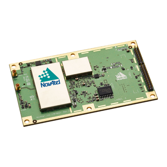
Weight 31 grams NovAtel Part Number Generic assembly OEM719 01019520 See the following sections for more information about the OEM719: OEM719 Performance Specifications on the next page OEM719 Mechanical Specifications on page 129 OEM719 Electrical and Environmental Specifications on page 136 OEM719 Data Communication Specifications on page 138 OEM719 Strobe Specifications on page 140... -
Page 127: Oem719 Performance Specifications
GNSS system characteristics, Signal-in-Space (SIS) operational degradation, ionospheric and tropospheric conditions, satellite geometry, baseline length, multipath effects and the presence of intentional or unintentional interference sources. GPS-only. Requires a TerraStar subscription which is available direct from NovAtel www.novatel.com/products/novatel- correct-ppp. Performance dependent on local observing conditions. - Page 128 APPENDIX A OEM719 Technical Specifications <0.5 s L1 (typical) Signal Reacquisition <1.0 s L2 and L5 (typical) Measurements up to 100 Hz Data Rates Position up to 100 Hz Time Accuracy 20 ns RMS Velocity Accuracy <0.03 m/s RMS Code...
-
Page 129: Oem719 Mechanical Specifications
APPENDIX A OEM719 Technical Specifications A.2 OEM719 Mechanical Specifications Figure 42: OEM719 Dimensions below Figure 43: OEM719 Keep-outs on the next page Figure 44: OEM719A Dimensions on page 131 Figure 45: OEM719A Keep-outs on page 132 Figure 46: OEM719B Dimensions on page 133 Figure 47: OEM719B Keep-outs on page 134... -
Page 130: Figure 43: Oem719 Keep-Outs
APPENDIX A OEM719 Technical Specifications Figure 43: OEM719 Keep-outs OEM7 Installation and Operation User Manual v4... -
Page 131: Figure 44: Oem719A Dimensions
APPENDIX A OEM719 Technical Specifications Figure 44: OEM719A Dimensions OEM7 Installation and Operation User Manual v4... -
Page 132: Figure 45: Oem719A Keep-Outs
APPENDIX A OEM719 Technical Specifications Figure 45: OEM719A Keep-outs OEM7 Installation and Operation User Manual v4... -
Page 133: Figure 46: Oem719B Dimensions
APPENDIX A OEM719 Technical Specifications Figure 46: OEM719B Dimensions OEM7 Installation and Operation User Manual v4... -
Page 134: Figure 47: Oem719B Keep-Outs
APPENDIX A OEM719 Technical Specifications Figure 47: OEM719B Keep-outs OEM7 Installation and Operation User Manual v4... -
Page 135: Figure 48: Oem719 Mounting Surface
OEM719. These mounting surfaces are designed to work with mounting rails. For information about mount- ing the OEM719, refer to Mounting the Printed Circuit Board on page 27. Assembly tolerances must be considered when using mounting rail features. OEM7 Installation and Operation User Manual v4... -
Page 136: Oem719 Electrical And Environmental Specifications
APPENDIX A OEM719 Technical Specifications A.3 OEM719 Electrical and Environmental Specifications Table 15: OEM719 Environmental Specifications Operating Temperature -40°C to +85°C Storage Temperature -55°C to +95°C Humidity 95% non-condensing Random Vibration MIL-STD 810G Method 514.7, Category 24 (20 g RMS) -
Page 137: Table 17: Oem719 Rf Input/Lna Power Output
LNA Power LNA Power is generated from the 3.3 V supply input for the OEM719. Note: Pin 1 of P1701 is not electrically connected on the OEM719. This was the external LNA power input (LNA-PWR) on the OEM615. OEM7 Installation and Operation User Manual v4... -
Page 138: Oem719 Data Communication Specifications
APPENDIX A OEM719 Technical Specifications A.4 OEM719 Data Communication Specifications Table 18: OEM719 Data Communication Interfaces COM1 Electrical format LVCMOS 2400, 4800, 9600 (default), 19200, 38400, 57600, 115200, 230400 or Data rates 460800 bit/s. Signals supported COM1_Tx, COM1_Rx Electrostatic discharge... - Page 139 APPENDIX A OEM719 Technical Specifications Electrical format LVCMOS (requires external CAN transceiver) 250, 500 or 1000 kb/s Data rates CAN Bus throughput is determined by slowest device on the bus Signals supported CAN1Tx, CAN1Rx, CAN2Tx, CAN2Rx Electrical format Conforms to USB 2.0...
-
Page 140: Oem719 Strobe Specifications
APPENDIX A OEM719 Technical Specifications A.5 OEM719 Strobe Specifications Table 19: OEM719 Strobe Description Factory Strobes Input/Output Comment Default An input mark for which a pulse greater than 150 ns triggers certain logs to be generated. (Refer to the MARKPOS and MARKTIME logs and ONMARK trigger.) -
Page 141: Table 20: Oem719 Strobe Electrical Specification
APPENDIX A OEM719 Technical Specifications Table 20: OEM719 Strobe Electrical Specification Current Strobe (mA) Event1 (Mark1) Event2 (Mark2) nRESET_IN VARF OEM7 Installation and Operation User Manual v4... -
Page 142: Oem719 Interface Connector
APPENDIX A OEM719 Technical Specifications A.6 OEM719 Interface Connector A.6.1 P1701 Main Connector 20-Pin Header Signal Signal Signal Drive Description Name Type Direction (mA) No internal connection on OEM719 receiver. (This pin was the supply feed for the external GNSS antenna on the OEM6 family. - Page 143 APPENDIX A OEM719 Technical Specifications Signal Signal Signal Drive Description Name Type Direction (mA) This pin is internally multiplexed. USB_D+ is the default. USB_D+: Input/ USB_D+: This is one half Output of a USB differential pair USB_ Analog (pins 3 and 4), match /3.3V...
- Page 144 APPENDIX A OEM719 Technical Specifications Signal Signal Signal Drive Description Name Type Direction (mA) This pin is internally multiplexed. EVENT2 is EVENT2: the default. Input EVENT2: Rising edge triggered. EVENT2/ 3.3V CAN1TX CMOS CAN1TX is a CMOS-level signal, requiring an...
- Page 145 APPENDIX A OEM719 Technical Specifications Signal Signal Signal Drive Description Name Type Direction (mA) COM2 Transmit Data (UART) For SPAN applications, 3.3V TXD2 Output this pin can be CMOS configured to output a timing signal periodically (generally 1PPS). COM2 Receive Data (UART) 3.3V...
-
Page 146: Appendix B Oem729 Technical Specifications
Size 60 mm x 100 mm x 9 mm Weight 48 grams NovAtel Part Number Generic assembly OEM729 01019523 See the following sections for more information about the OEM729: OEM729 Performance Specifications on the next page OEM729 Mechanical Specifications on page 149 OEM729 Electrical and Environmental Specifications on page 152... -
Page 147: Oem729 Performance Specifications
GNSS system characteristics, Signal-in-Space (SIS) operational degradation, ionospheric and tropospheric conditions, satellite geometry, baseline length, multipath effects and the presence of intentional or unintentional interference sources. GPS-only. Requires a TerraStar subscription which is available direct from NovAtel www.novatel.com/products/novatel- correct-ppp. Performance dependent on local observing conditions. - Page 148 APPENDIX B OEM729 Technical Specifications <0.5 s L1 (typical) Signal Reacquisition <1.0 s L2 and L5 (typical) Measurements up to 100 Hz Data Rates Position up to 100 Hz Time Accuracy 20 ns RMS Velocity Accuracy <0.03 m/s RMS Code Carrier L1 C/A 4 cm...
-
Page 149: Oem729 Mechanical Specifications
APPENDIX B OEM729 Technical Specifications B.2 OEM729 Mechanical Specifications Figure 49: OEM729 Dimensions below Figure 50: OEM729 Keep-outs on the next page Figure 51: OEM729 Mounting Surfaces on page 151 Figure 49: OEM729 Dimensions OEM7 Installation and Operation User Manual v4... -
Page 150: Figure 50: Oem729 Keep-Outs
APPENDIX B OEM729 Technical Specifications Figure 50: OEM729 Keep-outs OEM7 Installation and Operation User Manual v4... -
Page 151: Figure 51: Oem729 Mounting Surfaces
APPENDIX B OEM729 Technical Specifications Figure 51: OEM729 Mounting Surfaces The mounting surfaces are shown in gray. For information about mounting the OEM729, refer to Mounting the Printed Circuit Board on page 27. Assembly tolerances must be considered when using mounting rail features. OEM7 Installation and Operation User Manual v4... -
Page 152: Oem729 Electrical And Environmental Specifications
APPENDIX B OEM729 Technical Specifications B.3 OEM729 Electrical and Environmental Specifications Table 23: OEM729 Environmental Specifications Operating Temperature -40°C to +85°C Storage Temperature -55°C to +95°C Humidity 95% non-condensing Random Vibration MIL-STD 810G, Method 514.7, Category 24 (20 g RMS) Sinusoidal Vibration IEC 60068-2-6 Bump... -
Page 153: Table 25: Oem729 Rf Input/Lna Power Output
APPENDIX B OEM729 Technical Specifications Table 25: OEM729 RF Input/LNA Power Output Antenna Connector MMCX female, 50 Ω nominal impedance Cascaded antenna HDR disabled +15 dB to +40 dB, 26 dB typical LNA gain (before HDR enabled +20 dB to +40 dB, 30 dB typical receiver) 1575.42 MHz GPS L1:... -
Page 154: Oem729 Data Communication Specifications
APPENDIX B OEM729 Technical Specifications B.4 OEM729 Data Communication Specifications Table 27: Data Communications Interface COM1 Electrical format RS-232/RS-422 2400, 4800, 9600 (default), 19200, 38400, 57600, 115200, 230400 or Data rates 460800 bit/s. Signals supported COM1_Tx, COM1_Rx, COM1_RTS, COM1_CTS Electrostatic discharge protection COM2 Electrical format... - Page 155 APPENDIX B OEM729 Technical Specifications 1 Mbps maximum. Data rates CAN Bus throughput is determined by slowest device on the bus Signals supported CAN1 and CAN2 Electrical format Conforms to USB 2.0 Data rates Full-speed (12 Mb/s) Signals supported USB D (+), USB D (-) ETHERNET Physical layer 10BASE-T/100BASE-TX...
-
Page 156: Oem729 Strobe Specifications
APPENDIX B OEM729 Technical Specifications B.5 OEM729 Strobe Specifications Table 28: OEM729 Strobes Description Factory Strobes Input/Output Comment Default Normally low. Active A high output on this pin indicates that the receiver is in ERROR Output high an error state. For information about the cause of the error, log the RXSTATUS log. -
Page 157: Table 29: Oem729 Strobe Electrical Specifications
APPENDIX B OEM729 Technical Specifications Table 29: OEM729 Strobe Electrical Specifications Current Strobe (mA) ERROR Event1 (Mark ) Event2 (Mark2) nRESET_IN VARF OEM7 Installation and Operation User Manual v4... -
Page 158: Oem729 Interface Connectors
APPENDIX B OEM729 Technical Specifications B.6 OEM729 Interface Connectors B.6.1 P1802 Main Connector 24-Pin Header Signal Signal Signal Drive Description Name Type Direction (mA) Ground reference User GPIO. 3.3V Input/ USER1 Internal 10 kΩ CMOS Output pulldown. Variable Frequency output 3.3V Edges can be VARF... - Page 159 APPENDIX B OEM729 Technical Specifications Signal Signal Signal Drive Description Name Type Direction (mA) This pin is internally multiplexed. COM3_RX: COM3 receive data input. COM3_ 3.3V EVENT2 input. Rising or Input CMOS falling edge triggered. EVENT2 This is used to provide position or time data on an external trigger.
- Page 160 APPENDIX B OEM729 Technical Specifications Signal Signal Signal Drive Description Name Type Direction (mA) COM2 Clear To Send input This is an optional flow COM2_ 3.3V Input control signal for the CMOS COM2 UART. Internal weak (40 kΩ to 100 kΩ) pullup. Active Low.
- Page 161 APPENDIX B OEM729 Technical Specifications Signal Signal Signal Drive Description Name Type Direction (mA) This pin is internally multiplexed. COM1_CTS COM1_ is the default. CTS: Input COM1_CTS: COM1 Clear To Send input. This is COM1_ an optional flow control CTS/ signal for the COM1 COM1_ UART (±25V tolerant).
- Page 162 APPENDIX B OEM729 Technical Specifications Signal Signal Signal Drive Description Name Type Direction (mA) This pin is internally COM1_ multiplexed. COM1_RX is the default. Input COM1_RX: COM1 COM1_ Receive Data input (±25V tolerant). COM1_ COM1_RXD+: This is RXD+ COM1_ one half of the COM1 RXD+: Input RS-422 receive...
-
Page 163: P1803 Expansion Connector 16-Pin Header
APPENDIX B OEM729 Technical Specifications Signal Signal Signal Drive Description Name Type Direction (mA) USB device signal. This is one half of the USB differential pair. Input/ USB_D- Analog USB_D+ and USB_D- Output must be length- matched and routed as a 90 Ω... - Page 164 APPENDIX B OEM729 Technical Specifications Signal Signal Signal Drive Description Name Type Direction (mA) This is one half of the ETH_ Ethernet transmit Analog Output differential pair (100 Ω pair). This is one half of the ETH_ Ethernet transmit Analog Output differential pair (100 Ω...
- Page 165 APPENDIX B OEM729 Technical Specifications Signal Signal Signal Drive Description Name Type Direction (mA) USB Port Mode Leave this pin floating to ensure the USB port is in Device mode. 3.3V Input CMOS Host mode is not currently supported on the OEM729.
-
Page 166: Appendix C Oem7700 Technical Specifications
Size 46 mm x 71 mm x 8 mm Weight 31 grams NovAtel Part Number Generic assembly OEM7700 01019525 See the following sections for more information about the OEM7700: OEM7700 Performance Specifications on the next page OEM7700 Mechanical Specifications on page 169 OEM7700 Electrical and Environmental Specifications on page 172... -
Page 167: Oem7700 Performance Specifications
GNSS system characteristics, Signal-in-Space (SIS) operational degradation, ionospheric and tropospheric conditions, satellite geometry, baseline length, multipath effects and the presence of intentional or unintentional interference sources. GPS-only. Requires a TerraStar subscription which is available direct from NovAtel www.novatel.com/products/novatel- correct-ppp. Performance dependent on local observing conditions. - Page 168 APPENDIX C OEM7700 Technical Specifications <0.5 s L1 (typical) Signal Reacquisition <1.0 s L2 and L5 (typical) Measurements up to 100 Hz Data Rates Position up to 100 Hz Time Accuracy 20 ns RMS Velocity Accuracy <0.03 m/s RMS Code Carrier L1 C/A 4 cm...
-
Page 169: Oem7700 Mechanical Specifications
APPENDIX C OEM7700 Technical Specifications C.2 OEM7700 Mechanical Specifications Figure 52: OEM7700 Dimensions below Figure 53: OEM7700 Keep-outs on the next page Figure 54: OEM7700 Mounting Surfaces on page 171 Figure 52: OEM7700 Dimensions OEM7 Installation and Operation User Manual v4... -
Page 170: Figure 53: Oem7700 Keep-Outs
APPENDIX C OEM7700 Technical Specifications Figure 53: OEM7700 Keep-outs OEM7 Installation and Operation User Manual v4... -
Page 171: Figure 54: Oem7700 Mounting Surfaces
APPENDIX C OEM7700 Technical Specifications Figure 54: OEM7700 Mounting Surfaces The mounting surfaces are shown in gray. These mounting surfaces are designed to work with mounting rails. For information about mount- ing the OEM7700, refer to Mounting the Printed Circuit Board on page 27. Assembly tolerances must be considered when using mounting rail features. -
Page 172: Oem7700 Electrical And Environmental Specifications
APPENDIX C OEM7700 Technical Specifications C.3 OEM7700 Electrical and Environmental Specifications Table 32: OEM7700 Environmental Specifications Operating Temperature -40°C to +85°C Storage Temperature -55°C to +95°C Humidity 95% non-condensing Random Vibration MIL-STD 810G, Method 514.7, Category 24 (20 g RMS) Sinusoidal Vibration IEC 60068-2-6 Bump... -
Page 173: Table 34: Oem7700 Rf Input/Lna Power Output
APPENDIX C OEM7700 Technical Specifications Table 34: OEM7700 RF Input/LNA Power Output Antenna Connector MMBX female, 50 Ω nominal impedance Cascaded antenna HDR disabled +15 dB to + 40 db, 26 dB typical LNA gain (before HDR enabled +20 dB to + 40 db, 30 dB typical receiver) 1575.42 MHz GPS L1:... -
Page 174: Oem7700 Data Communication Specifications
APPENDIX C OEM7700 Technical Specifications C.4 OEM7700 Data Communication Specifications Table 35: Data Communications Interface COM1 Electrical format LVCMOS 2400, 4800, 9600 (default), 19200, 38400, 57600, 115200, 230400 or Data rates 460800 bit/s. Signals supported COM1_Tx, COM1_Rx, COM1_RTS, COM1_CTS Electrostatic discharge protection COM2 Electrical format... - Page 175 APPENDIX C OEM7700 Technical Specifications COM5 Electrical format LVCMOS 2400, 4800, 9600 (default), 19200, 38400, 57600, 115200, 230400 or Data rates 460800 bit/s. Signals supported COM5_Tx, COM5_Rx Electrostatic discharge protection CAN Bus Electrical Format LVCMOS 1 Mbps maximum. Data rates CAN Bus throughput is determined by slowest device on the bus Signals supported CAN0 and CAN1...
-
Page 176: Oem7700 Strobe Specifications
APPENDIX C OEM7700 Technical Specifications C.5 OEM7700 Strobe Specifications Table 36: OEM7700 Strobes Description Factory Strobes Input/Output Comment Default Normally low. Active A high output on this pin indicates that the receiver ERROR Output high is in an error state. For information about the cause of the error, log the RXSTATUS log. -
Page 177: Table 37: Oem7700 Strobe Electrical Specifications
APPENDIX C OEM7700 Technical Specifications Factory Strobes Input/Output Comment Default A time synchronization output. This is a pulse where the leading edge is synchronized to receiver Active Output calculated GNSS Time. The polarity, period and pulse width can be configured using the PPSCONTROL command Table 37: OEM7700 Strobe Electrical Specifications Current... -
Page 178: Oem7700 Interface Connector
APPENDIX C OEM7700 Technical Specifications C.6 OEM7700 Interface Connector C.6.1 P2001 Main Connector 60-Pin Socket Signal Signal Signal Drive Description Name Type Direction (mA) Power Input 3.3 V ±5% supply input Power Input 3.3 V ±5% supply input COM2 Transmit Data (UART) For SPAN applications, COM2_... - Page 179 APPENDIX C OEM7700 Technical Specifications Signal Signal Signal Drive Description Name Type Direction (mA) COM1 Request to Send COM1_ 3.3V Optional hardware flow Output CMOS control signal for the COM1 serial port. Ground Ground reference Ground Ground reference COM2_ 3.3V COM2 Receive Data Input CMOS...
- Page 180 APPENDIX C OEM7700 Technical Specifications Signal Signal Signal Drive Description Name Type Direction (mA) Used to indicate the state of the receiver or provide error codes. These outputs provide STATUS_ 3.3V the same information Output GREEN CMOS as the Status Indicator LED (see Status LED on page 89).
- Page 181 APPENDIX C OEM7700 Technical Specifications Signal Signal Signal Drive Description Name Type Direction (mA) COM4_ 3.3V COM4 Transmit Data Output CMOS (UART) COM3_ 3.3V COM3 Transmit Data Output CMOS (UART) Error Indicator (Active High) Normally low. A high output on this pin 3.3V ERROR Output...
- Page 182 APPENDIX C OEM7700 Technical Specifications Signal Signal Signal Drive Description Name Type Direction (mA) Pulse Per Second output This signal defaults to one pulse per second but may be altered 3.3V across a wide range of Output 0.55 CMOS frequencies using software commands.
- Page 183 APPENDIX C OEM7700 Technical Specifications Signal Signal Signal Drive Description Name Type Direction (mA) EVENT1 (Mark1) input Rising or falling edge triggered. This input is EVENT_ 3.3V used to provide a Input CMOS position or time data log based on an external trigger.
- Page 184 APPENDIX C OEM7700 Technical Specifications Signal Signal Signal Drive Description Name Type Direction (mA) CAN1 Transmit Data This is a CMOS-level CAN1_ 3.3V Output signal, requiring an CMOS external CAN transceiver. CAN0 Receive Data This is a CMOS-level CAN0_ 3.3V Input signal, requiring an CMOS...
- Page 185 APPENDIX C OEM7700 Technical Specifications Signal Signal Signal Drive Description Name Type Direction (mA) USB0 signal. This is one half of the USB0 differential pair. USB0_ Analog USB0_D+ and USB0_D- must be length- matched and routed as a 90 Ω differential pair. USB1 signal.
- Page 186 APPENDIX C OEM7700 Technical Specifications Signal Signal Signal Drive Description Name Type Direction (mA) When the USB port mode is set to Host, this pin is an output. When the USB port mode is set to Device, this pin is an input. Host or Device mode is set using the USB_Port_ Mode_Select pin (Pin...
- Page 187 APPENDIX C OEM7700 Technical Specifications Signal Signal Signal Drive Description Name Type Direction (mA) Ethernet Link and Activity LED indicator. Polarity of the indicator signal is low. When there is an active link, ETH_ 3.3V the pin is low. When LINK_ Output CMOS...
- Page 188 APPENDIX C OEM7700 Technical Specifications Signal Signal Signal Drive Description Name Type Direction (mA) Ethernet Transmit One half of the Ethernet transmit differential ETH_TX- Analog Output pair. ETH_TX+ and ETH_TX- must be routed as a 100 Ω differential pair. OEM7 Installation and Operation User Manual v4...
-
Page 189: Table 38: Oem7720 Physical Description
Size 46 mm x 71 mm x 7.5 mm Weight 29 grams NovAtel Part Number Generic Assembly OEM7720 01019906 See the following sections for more information about the OEM7720: OEM7720 Performance Specifications on the next page OEM7720 Mechanical Specifications on page 193 OEM7720 Electrical and Environmental Specifications on page 196... -
Page 190: Appendix D Oem7720 Technical Specifications
GNSS system characteristics, Signal-in-Space (SIS) operational degradation, ionospheric and tropospheric conditions, satellite geometry, baseline length, multipath effects and the presence of intentional or unintentional interference sources. GPS-only. Requires a TerraStar subscription which is available direct from NovAtel www.novatel.com/products/novatel- correct-ppp. Performance dependent on local observing conditions. - Page 191 APPENDIX D OEM7720 Technical Specifications L1 C/A, L1C, L2C, L2P GLONASS L1 C/A, L2 C/A, L2P, L3 Signals Tracked BeiDou B1, B2 Secondary Galileo E1, E5b Antenna QZSS L1 C/A, L1C, L2C SBAS Hot: <26 s (Almanac and recent ephemeris saved and approximate position and time entered) Time to First Fix Cold: <46 s (No almanac or ephemeris and no approximate position or time)
- Page 192 APPENDIX D OEM7720 Technical Specifications Code Carrier L1 C/A 4 cm 0.5 mm L2 P(Y) 8 cm 1.0 mm 8 cm 0.5 mm 3 cm 0.5 mm L1 C/A 8 cm 1.0 mm GLONASS L2 P 8 cm 1.0 mm Measurement Precision L2 C/A...
-
Page 193: Oem7720 Mechanical Specifications
APPENDIX D OEM7720 Technical Specifications D.2 OEM7720 Mechanical Specifications Figure 55: OEM7720 Dimensions below Figure 56: OEM7720 Keep-outs on the next page Figure 57: OEM7720 Mounting Surfaces on page 195 Figure 55: OEM7720 Dimensions OEM7 Installation and Operation User Manual v4... -
Page 194: Figure 56: Oem7720 Keep-Outs
APPENDIX D OEM7720 Technical Specifications Figure 56: OEM7720 Keep-outs OEM7 Installation and Operation User Manual v4... -
Page 195: Figure 57: Oem7720 Mounting Surfaces
APPENDIX D OEM7720 Technical Specifications Figure 57: OEM7720 Mounting Surfaces The mounting surfaces are shown in gray. These mounting surfaces are designed to work with mounting rails. For information about mount- ing the OEM7720, refer to Mounting the Printed Circuit Board on page 27. Assembly tolerances must be considered when using mounting rail features. -
Page 196: Oem7720 Electrical And Environmental Specifications
APPENDIX D OEM7720 Technical Specifications D.3 OEM7720 Electrical and Environmental Specifications Table 40: OEM7720 Environmental Specifications Operating Temperature -40°C to +85°C Storage Temperature -55°C to +95°C Humidity 95% non-condensing Random Vibration MIL-STD 810G, Method 514.7, Category 24 (20 g RMS) Sinusoidal Vibration IEC 60068-2-6 Bump... -
Page 197: Table 42: Oem7720 Rf Input/Lna Power Output
APPENDIX D OEM7720 Technical Specifications Table 42: OEM7720 RF Input/LNA Power Output Antenna Connector MMBX female, 50 Ω nominal impedance Cascaded antenna HDR disabled +15 dB to +40 dB, 26 dB typical LNA gain (before HDR enabled +20 dB to +40 dB, 30 dB typical receiver) 1575.42 MHz GPS L1:... -
Page 198: Oem7720 Data Communication Specifications
APPENDIX D OEM7720 Technical Specifications D.4 OEM7720 Data Communication Specifications Table 43: Data Communications Interface COM1 Electrical format LVCMOS 2400, 4800, 9600 (default), 19200, 38400, 57600, 115200, 230400 or Data rates 460800 bit/s. Signals supported COM1_Tx, COM1_Rx, COM1_RTS, COM1_CTS Electrostatic discharge protection COM2 Electrical format... - Page 199 APPENDIX D OEM7720 Technical Specifications COM5 Electrical format LVCMOS 2400, 4800, 9600 (default), 19200, 38400, 57600, 115200, 230400 or Data rates 460800 bit/s. Signals supported COM5_Tx, COM5_Rx Electrostatic discharge protection CAN Bus Electrical Format LVCMOS 1 Mbps maximum. Data rates CAN Bus throughput is determined by slowest device on the bus Signals supported CAN0 and CAN1...
-
Page 200: Oem7720 Strobe Specifications
APPENDIX D OEM7720 Technical Specifications D.5 OEM7720 Strobe Specifications Table 44: OEM7720 Strobes Description Factory Strobes Input/Output Comment Default Normally low. Active A high output on this pin indicates that the receiver ERROR Output high is in an error state. For information about the cause of the error, log the RXSTATUS log. -
Page 201: Table 45: Oem7720 Strobe Electrical Specifications
APPENDIX D OEM7720 Technical Specifications Factory Strobes Input/Output Comment Default A time synchronization output. This is a pulse where the leading edge is synchronized to receiver Active Output calculated GNSS Time. The polarity, period and pulse width can be configured using the PPSCONTROL command Table 45: OEM7720 Strobe Electrical Specifications Current... -
Page 202: Oem7720 Interface Connector
APPENDIX D OEM7720 Technical Specifications D.6 OEM7720 Interface Connector D.6.1 P1901 Main Connector 60-Pin Socket Signal Signal Signal Drive Description Name Type Direction (mA) 3.2 to 5.0 V ±5% supply Power Input input 3.2 to 5.0 V ±5% supply Power Input input COM2 Transmit Data... - Page 203 APPENDIX D OEM7720 Technical Specifications Signal Signal Signal Drive Description Name Type Direction (mA) This pin is internally multiplexed. COM5_TXD is the default. COM5_ COM5_TXD: COM5 TXD/ 3.3V Output Transmit Data (UART). COM2_ CMOS COM2_RTS: COM2 Request to Send Optional hardware flow control signal for the COM2 serial port.
- Page 204 APPENDIX D OEM7720 Technical Specifications Signal Signal Signal Drive Description Name Type Direction (mA) COM4_ 3.3V COM4 Receive Data Input CMOS (UART) COM3_ 3.3V COM3 Receive Data Input CMOS (UART) Used to indicate the state of the receiver or provide error codes. These outputs provide STATUS_ 3.3V...
- Page 205 APPENDIX D OEM7720 Technical Specifications Signal Signal Signal Drive Description Name Type Direction (mA) Receiver Ready (Active High) Indicates to the host system that the receiver is ready to 3.3V receive commands. ME_RDY Output CMOS This signal is not asserted while booting or during a reset.
- Page 206 APPENDIX D OEM7720 Technical Specifications Signal Signal Signal Drive Description Name Type Direction (mA) EVENT3 (Mark3) Output Rising edge triggered. Outputs a user- EVENT_ 3.3V specified timing signal. Output OUT3 CMOS Can be synchronized with PPS. Supports Variable Frequency Output function. Pulse Per Second output This signal defaults to one pulse per second...
- Page 207 APPENDIX D OEM7720 Technical Specifications Signal Signal Signal Drive Description Name Type Direction (mA) EVENT2 (Mark2) input Rising or falling edge triggered. This input is EVENT_ 3.3V used to provide a Input CMOS position or time data log based on an external trigger.
- Page 208 APPENDIX D OEM7720 Technical Specifications Signal Signal Signal Drive Description Name Type Direction (mA) CAN1 Receive Data This is a CMOS-level CAN1_ 3.3V Input signal, requiring an CMOS external CAN transceiver. CAN0 Transmit Data This is a CMOS-level CAN0_ 3.3V Output signal, requiring an CMOS...
- Page 209 APPENDIX D OEM7720 Technical Specifications Signal Signal Signal Drive Description Name Type Direction (mA) Ground Ground reference USB1 signal. This is one half of the USB1 differential pair. USB1_D- Analog USB1_D+ and USB1_D- must be length- matched and routed as a 90 Ω...
- Page 210 APPENDIX D OEM7720 Technical Specifications Signal Signal Signal Drive Description Name Type Direction (mA) USB Port Mode Select. Leave this pin floating to put USB0 into Device mode and USB1 into Host mode. 3.3V Input CMOS Tie this pin to GND to put USB0 into Host mode and USB1 into Device mode.
- Page 211 APPENDIX D OEM7720 Technical Specifications Signal Signal Signal Drive Description Name Type Direction (mA) Reset Input (Active Low) Resets the receiver card when low. This pin nRESET_ 3.3V Input 2.55 must be held low for a CMOS minimum of 100 microseconds to guarantee operation.
- Page 212 APPENDIX D OEM7720 Technical Specifications Signal Signal Signal Drive Description Name Type Direction (mA) Ethernet Transmit One half of the Ethernet transmit differential ETH_TX+ Analog Output pair. ETH_TX+ and ETH_TX- must be routed as a 100 Ω differential pair. Ethernet Receive One half of the Ethernet receive differential ETH_RX-...
-
Page 213: Appendix E Receiver Card Interface Examples
APPENDIX E Receiver Card Interface Examples The OEM7 receiver cards provide a number of 3.3V CMOS-level I/O pins for status indication and timing: COMx: CMOS-level UART ports Ethernet: 10/100 Ethernet port CAN1 and CAN2: CMOS-level CAN ports (external CAN transceivers required) PPS: Output pulse providing time reference signal (software configurable output rate, defaults to 1 Pulse Per Second) EVENTx_OUT: Variable Frequency output (a software-configurable clock output similar to... -
Page 214: Event_In, Event_Out And Pps Signal Protection
This design has been used to protect EVENT_IN sig- nals from EN61000-4-5 induced surges up to 2kV on several NovAtel enclosure products. If nano- second-level timing is critical to the application, this protection circuit may be unsuitable, as it causes a timing shift of a few microseconds to the EVENT signal (heavily dependent on tem- perature). -
Page 215: Table 46: Event_In, Event_Out And Pps Pin Designation
The 10 kΩ pullups (R5, R6) are required if the buffers are used on the EVENT_IN lines. If the buf- fers are not used, the OEM7 cards have built-in 10 kΩ pullup resistors – external pull resistors are not required. Table 46: EVENT_IN, EVENT_OUT and PPS Pin Designation OEM719 OEM729 OEM7700 OEM7720... -
Page 216: Position Valid (Pv) Led Driver
The PV signal may be used to indicate that the receiver card has computed a valid position. Many NovAtel enclosure products use it to drive a green LED on the enclosure. It may also be used to monitor the status of the receiver with an external microcontroller. -
Page 217: Communication Ports
APPENDIX E Receiver Card Interface Examples E.3 Communication Ports The COM ports on OEM7 receivers (except COM1 on the OEM729) are CMOS-level I/O pins only. These ports require the addition of an RS232 or RS422 transceiver to provide appropriate signal levels. -
Page 218: Can Controller Ports
The combination of ferrite beads and small-value capacitors are not necessarily required but may provide improved EMI performance. A low-capacitance TVS device is shown on the schem- atic to provide ESD protection. Figure 60: OEM7 CAN Transceiver Example Table 50: CAN Transceiver Pin Designation OEM719 OEM729 OEM7700 OEM7720 Connector... -
Page 219: Usb Interface
OEM7 receivers include an USB 2.0 device interface set to either Full-Speed (12 Mb/s) or High- Speed (480 Mb/s) transfer rate. On the OEM719 and OEM729 receivers, the transfer rate for the USB Device port is Full-Speed (12 Mb/s). The USB device interface on the OEM7700 and OEM7720 receivers use the High-Speed (480 Mb/s) transfer rate. -
Page 220: Table 52: Usb Device Interface Pin Designation
APPENDIX E Receiver Card Interface Examples Table 52: USB Device Interface Pin Designation OEM719 OEM729 OEM7700 OEM7720 Connector P1701 P1802 P1803 P2001 P1901 USB0_D- USB0_D+ USB1_D- USB1_D+ USB_ VBUS Table 53: USB Device Interface Example Bill of Materials Designator Manufacturer... -
Page 221: Figure 62: Oem7 Usb Host Device Interface Example
APPENDIX E Receiver Card Interface Examples Figure 62: OEM7 USB Host Device Interface Example Table 54: USB Host Interface Pin Designation OEM719 OEM729 OEM7700 OEM7720 Connector P1701 P1802 P1803 P2001 P1901 USB0_D- USB0_D+ USB1_D- USB1_D+ USB_ VBUS Table 55: USB Host Interface Example Bill of Materials... - Page 222 APPENDIX E Receiver Card Interface Examples Designator Manufacturer Manufacturer Part Number Molex 0482040001 Wurth Electronics 744230450 OEM7 Installation and Operation User Manual v4...
-
Page 223: Ethernet Port
APPENDIX E Receiver Card Interface Examples E.6 Ethernet Port OEM7 receivers, except the OEM719, provide a 10/100 Ethernet port with auto-negotiation. The Ethernet interface is disabled by default and must be configured. See the Ethernet Configuration for instructions on Ethernet device configuration. The PHY layer is based on the Texas Instru- ments TKL106 Ethernet PHY. -
Page 224: Table 57: Ethernet Transformer Characteristics
APPENDIX E Receiver Card Interface Examples acteristics on the next page. Ensure that the jack is no more than 15 cm (6 inches) from the OEM7 connector. Shorter runs are better. Table 57: Ethernet Transformer Characteristics Parameter Value Test Condition Turns ratio 1 CT : 1 CT Open-CCT inductance (minimum) -
Page 225: Appendix F Importance Of Antenna Selection
APPENDIX F Importance of Antenna Selection An antenna behaves both as a spatial and frequency filter, therefore, selecting the right GNSS antenna is critical for optimizing performance. An antenna must match the receiver’s cap- abilities and specifications, as well as meet size, weight, environmental and mechanical spe- cifications for the intended application. -
Page 226: Figure 64: Plot Of Good And Poor Antenna Phase Center Variation Over Elevation Angle
APPENDIX F Importance of Antenna Selection Figure 64: Plot of Good and Poor Antenna Phase Center Variation over Elevation Angle 0-90° Many users can accept accuracies of less than a metre so these small phase center vari- ations cause a negligible amount of position error. But if you require high precision, Real Time Kinematic (RTK) receivers can achieve position accuracies of 2-4 cm and a few mil- limetres of phase center error translates to a 10-15% error in reported position. - Page 227 APPENDIX F Importance of Antenna Selection temperatures and vibration profiles. Survey rover antennas should be able to survive rough handling by surveyors including a pole drop. The table below highlights some of the important desirable features needed for a GNSS antenna based upon the user’s application.
-
Page 228: Table 59: Accessories
APPENDIX G Accessories and Replacement Parts The following tables list the replacement parts available for your NovAtel OEM7 receiver. For assistance or to order additional components, contact your local NovAtel dealer or Customer Support. Table 59: Accessories NovAtel Part Part Description... -
Page 229: Manufacturers' Part Numbers
APPENDIX G Accessories and Replacement Parts NovAtel Part Part Description 01019751 10 mm rail for OEM719, OEM7700 and OEM7720 01019752 12 mm rail for OEM719 01020014 OEM7720 Accessory Heat Spreader G.1 Manufacturers’ Part Numbers The following original manufacturer’s part numbers are provided for information only and are not available from NovAtel as separate parts. -
Page 230: Appendix G Accessories And Replacement Parts
50h (Bulk-Only High Storage set) Transport) The devices in the following table have been tested by NovAtel and confirmed to be compatible with the USB host system on OEM7 receivers. Table 61: Devices Tested for OEM7 USB Embedded Host Class Manufacturer Model Vendor ID... - Page 231 APPENDIX G Accessories and Replacement Parts If multiple mass storage devices are connected to the USB port during boot up, there is no way to predict which device is mounted and used. OEM7 Installation and Operation User Manual v4...
-
Page 232: Appendix H Electrostatic Discharge (Esd) Practices
APPENDIX H Electrostatic Discharge (ESD) Practices Various electrical and electronic components are vulnerable to ESD. These include discrete com- ponents, hybrid devices, Integrated Circuits (ICs) and Printed Circuit Boards (PCBs) assembled with these devices. H.1 Handling ESD Sensitive Devices ESD sensitive devices must only be handled in static controlled locations. Some recom- mendations for such handling practices follow: Handling areas must be equipped with a grounded table, floor mats and wrist strap. -
Page 233: Prime Static Accumulators
APPENDIX H Electrostatic Discharge (ESD) Practices Do not allow chargeable plastics, such as binders, within 0.6 m of unshielded PCBs. Do not allow a PCB to come within 0.3 m of a computer monitor. H.2 Prime Static Accumulators Table 62: Static-Accumulating Materials below provides some background information on static accumulating materials. - Page 234 APPENDIX H Electrostatic Discharge (ESD) Practices 3. Place the original board into the shielding bag or clamshell and seal it with a label. 4. Do not put repair tags inside the shielding bag or clamshell. 5. Disconnect the wrist strap. OEM7 Installation and Operation User Manual v4...
- Page 235 OEM7 Installation and Operation User Manual v4...
Need help?
Do you have a question about the OEM719 and is the answer not in the manual?
Questions and answers