Table of Contents
Advertisement
Advertisement
Table of Contents

Related Manuals for Novatel PwrPak7


Summary of Contents for Novatel PwrPak7
- Page 1 PwrPak7 Installation and Operation User Manual OM-20000173 v1A November 2017...
-
Page 2: Pwrpak7 Installation And Operation User Manual
Information in this document is subject to change without notice and does not represent a com- mitment on the part of NovAtel Inc. The software described in this document is furnished under a licence agreement or non-disclosure agreement. The software may be used or copied only in accordance with the terms of the agreement. -
Page 3: Table Of Contents
2.3 Optional Accessories 2.4 PwrPak7 Cables 2.5 Selecting a GNSS Antenna 2.6 Choosing a Coaxial Cable 2.7 Power Supply Requirements for the PwrPak7 2.8 PwrPak7 Installation Overview 2.9 Mounting the GNSS Antenna 2.9.1 Antenna LNA Power 2.10 Mount the PwrPak7... - Page 4 PwrPak7 Installation and Operation User Manual 2.11 Mount the PwrPak7-E1 2.12 Connect the PwrPak7 to Data Communication Equipment 2.12.1 Serial Ports 2.12.2 USB Ports 2.12.3 Wi-Fi 2.12.4 Ethernet Port 2.12.5 CAN Bus Port 2.13 Connect I/O Signals to the PwrPak7 2.14 Connect Power to the PwrPak7...
- Page 5 7.2.2 Example of Enabling the CAN Bus 7.2.3 Example of Modifying the CAN Bus Parameters 7.2.4 Example of Detecting an Address Claim Failure and Reconfiguring 7.2.5 Address Claim Procedure 7.3 NMEA2000 Logging 7.3.1 Example of NMEA2000 Log Configuration PwrPak7 Installation and Operation User Manual v1A...
- Page 6 A.4 PwrPak7 Data Communication Specifications A.5 PwrPak7 Strobe Specifications A.6 PwrPak7 Connectors A.7 PwrPak7 Power Cable A.8 PwrPak7 All I/O Cable A.9 PwrPak7 COM1 Cable A.10 PwrPak7 IMU Cable APPENDIX B Importance of Antenna Selection PwrPak7 Installation and Operation User Manual v1A...
-
Page 7: Figures
Figure 2: PwrPak7 Connectors Figure 3: PwrPak7 Status Indicators Figure 4: PwrPak7 Installation Example Figure 5: Fuse for PwrPak7 Power Supply Figure 6: Dedicated Battery for PwrPak7 Figure 7: Seamless Battery Swap Figure 8: Basic Receiver Enclosure Connection Interfaces (example) - Page 8 Table 19: PwrPak7 Receiver Performance Table 20: PwrPak7-E1 IMU Performance Table 21: PwrPak7 Environmental Specifications Table 22: PwrPak7 Power Requirements Table 23: PwrPak7 RF Input/LNA Power Output Table 24: Data Communications Interfaces Table 25: PwrPak7 Strobes Description Table 26: PwrPak7 Strobe Electrical Specifications...
-
Page 9: Pwrpak7 Notices
Re-orient or relocate the PwrPak7 Increase the separation between the equipment and the PwrPak7 Connect the equipment to an outlet on a circuit different from that to which the PwrPak7 is connected Consult the dealer or an experienced radio/TV technician for help To maintain compliance with the limits of a Class B digital device, you must use shielded interface cables. -
Page 10: Wi-Fi
PwrPak7 Wi-Fi NovAtel Inc. declares that the PwrPak7 Wi-Fi transceiver is in compliance with Directive 2014/53/EU (Radio Equipment). The full text of the EU Declaration of Conformity may be obtained from the NovAtel web site at: www.novatel.com/products/compliance/eu-declaration-of-conformity Radio Information Description of Service: Wi-Fi (802.11b/g/n) -
Page 11: Rohs
RoHS The PwrPak7 is in conformity with Directive 2011/65/EU of the European Parliament and of the council of 8 June 2011 on the restriction of the use of certain hazardous substances in electrical and electronic equipment. -
Page 12: Lightning Protection Installation And Grounding Procedure
6. The primary and secondary lightning protections should be as close to the building's entrance as possible. Where feasible, mount onto the grounding plate itself (refer to the figure below). PwrPak7 Installation and Operation User Manual v1A... - Page 13 Where applicable, follow the electrical codes for the country of installation. Examples of country codes include: USA National Electrical Code (NFPA 70) Canada Canadian Electrical Code (CSA C22.1) UK British Standards Institute (BSI 7671) PwrPak7 Installation and Operation User Manual v1A...
-
Page 14: Conventions
A caution that actions, operation or configuration may lead to incorrect or improper use of the hardware. A warning that actions, operation or configuration may result in regulatory non- compliance, safety issues or equipment damage. PwrPak7 Installation and Operation User Manual v1A... -
Page 15: Customer Support
If you are having a hardware problem, send a list of the troubleshooting steps taken and the res- ults. Contact Information Log a support request with NovAtel Customer Support using one of the following methods: Log a Case and Search Knowledge: PwrPak7 Installation and Operation User Manual v1A... - Page 16 Customer Support Website: www.novatel.com/support Log a Case, Search Knowledge and View Your Case History: (login access required) Web Portal: https://novatelsupport.force.com/community/login E-mail: support@novatel.com Telephone: U.S. and Canada: 1-800-NOVATEL (1-800-668-2835) International: +1-403-295-4900 PwrPak7 Installation and Operation User Manual v1A...
-
Page 17: Chapter 1 Pwrpak7 And Pwrpak7-E1 Overview
Chapter 1 PwrPak7 and PwrPak7-E1 Overview NovAtel's PwrPak7 uses the OEM7700 card to deliver scalable high precision positioning in a com- pact, lightweight enclosure. Novatel's PwrPak7-E1 combines GNSS and INS hardware in a single enclosure to provide an easy to deploy SPAN GNSS+INS system. The PwrPak7-E1 uses an OEM7700 receiver card to deliver scalable high precision positioning and an Epson EG320N IMU to deliver accelerometer and gyroscope measurements. -
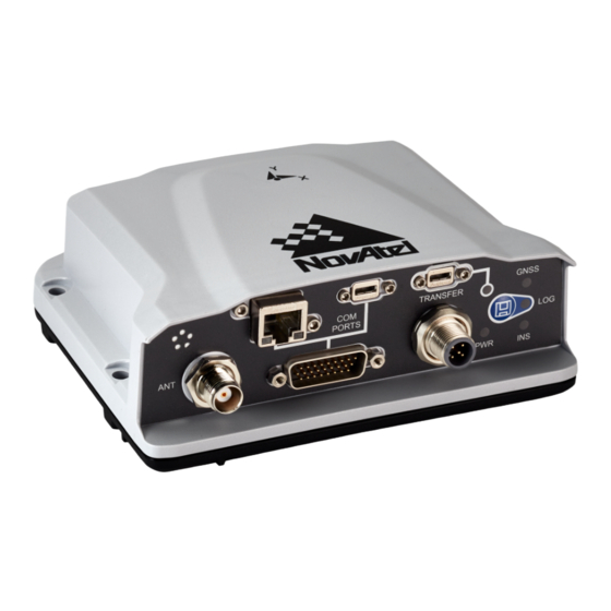
Page 18: Pwrpak7 Connectors
Figure 1: PwrPak7 Enclosure PwrPak7 and PwrPak7-E1 technical specifications are provided in PwrPak7 Specifications on page 115. 1.1 PwrPak7 Connectors The PwrPak7 has several connectors for connecting the receiver to other components in the GNSS system. Figure 2: PwrPak7 Connectors Table 1: PwrPak7 Connectors... -
Page 19: Pwrpak7 Leds
Refer to the PwrPak7 Connectors on page 126 for connector details. 1.2 PwrPak7 LEDs The PwrPak7 has five LEDs to indicate receiver status. It also has a button to start or stop data logging to a file. Figure 3: PwrPak7 Status Indicators... -
Page 20: Table 2: Pwrpak7 Status Indicators
Indicates the position status of the receiver Indicates the INS status of the receiver This LED is applicable only to SPAN capable PwrPak7 models (a PwrPak7-E1 or a PwrPak7 with an external IMU) Indicates the status of logging or file-transfer to a USB stick or connection to a... -
Page 21: Table 5: Ins Led
No connection to the TRANSFER port or the USB stick is unmounted Table 7: LOG (Onboard Storage) LED LED State Description PwrPak7 is connected to a computer as a mounted device See Access Internal Memory with a Computer on page 71 PwrPak7 Installation and Operation User Manual v1A... -
Page 22: Related Documents And Information
This manual does not cover OEM7 service and repair. Contact a local NovAtel dealer for service or repair inquiries (refer to Customer Support on page 15 for contact details). PwrPak7 Installation and Operation User Manual v1A... -
Page 23: Chapter 2 Pwrpak7 Installation
PwrPak7 before using Ethernet. When the PwrPak7 is installed in a permanent location, such as in a building, it should be protected by a lightning protection device according to local building codes. See Light- ning Protection Installation and Grounding Procedure on page 12. -
Page 24: Pwrpak7 Cables
Furthermore, the connectors used to mate the cables to the receiver require careful insertion and removal. Observe the following when handling cables. To insert a cable, make certain to use the appropriate cable for the PwrPak7 connector Insert the connector until it is on straight and secure To remove a cable, grasp it by the connector Do not pull directly on a cable. -
Page 25: Choosing A Coaxial Cable
European Union’s Restriction of Hazardous Substances (RoHS) and Waste Electrical and Electronic Equipment (WEEE). If a non-NovAtel GNSS antenna is chosen, a typical antenna LNA gain between 26 dB to 30 dB is recommended in a rover station application. -
Page 26: Pwrpak7 Installation Overview
The power cable included with the PwrPak7 has a connector on the receiver end (SAL M12 5 pin) and bare wires on the other end. Refer to PwrPak7 Power Cable on page 129 for details about the power cable. -
Page 27: Figure 4: Pwrpak7 Installation Example
2. Mount the receiver. For a PwrPak7, refer to Mount the PwrPak7 on the next page. For a PwrPak7-E1, refer to Mount the PwrPak7-E1 on page 29. 3. Connect one end of the antenna cable to the GNSS antenna and the other end of the cable to the antenna connector (ANT) on the receiver. -
Page 28: Mounting The Gnss Antenna
Chapter 2 PwrPak7 Installation The PwrPak7 supplies +5 VDC (200 mA maximum) to the antenna LNA through the center conductor of the antenna cable. See Antenna LNA Power on the next page for more inform- ation. 4. Connect the receiver to other GNSS system components, such as a computer or data ter- minal, using the communication ports or Wi-Fi. -
Page 29: Pwrpak7 Installation And Operation User Manual
Z-axis marked on the receiver points up and the Y-axis points forward through the front of the vehicle, in the direction of track. If the PwrPak7-E1 is not mounted in this orientation, a rota- tional offset must be applied. See the OEM7 SPAN Installation and Operation User Manual more information. -
Page 30: Connect The Pwrpak7 To Data Communication Equipment
PwrPak7 Data Communication Specifications on page 123 for the serial port specifications. To connect to a serial port: 1. Connect the PwrPak7 All I/O cable (PN: 01019766), or a custom made cable, to the HD26 COM PORTS connector. PwrPak7 Installation and Operation User Manual v1A... -
Page 31: Usb Ports
1. Once the receiver is installed and powered, use a Wi-Fi capable laptop/tablet/smartphone to locate the PwrPak7 in the list of detected Wi-Fi Networks and establish a connection. The PwrPak7 SSID is printed on a label on the bottom of the receiver. The format of the SSID is PwrPak7-<Receiver PSN>, e.g. "PwrPak7-ABCDEF1234567". -
Page 32: Ethernet Port
2.14 Connect Power to the PwrPak7 To connect power to the PwrPak7: 1. Connect the M12 connector of the PwrPak7 Power Cable on page 129 to the PWR port on the PwrPak7. 2. Connect the bare wires of the power cable to a 9 to 36 VDC power supply. -
Page 33: Fuse For The Power Supply
Install a user supplied 6 A slow blow fuse in the positive line of the connection to the power source to protect the power supply wiring and your warranty. Figure 5: Fuse for PwrPak7 Power Supply For a 12 V system, the following are recommended. -
Page 34: Vehicle Installation
When a vehicle engine is star- ted, the voltage on the starter battery can dip below the PwrPak7 minimum voltage or cut-out to ancillary equipment causing the receiver to lose lock and calibration settings. -
Page 35: Check That The Pwrpak7 Is Operating
PwrPak7 and/or connected equipment will result. 2.15 Check that the PwrPak7 is Operating After the PwrPak7 is installed, powered up and connected to a GNSS antenna, use the following procedure to ensure the receiver is operating. 1. Check that the PWR LED is solid green. - Page 36 It can take about a minute for time status to be FINESTEERING depending on number of satellites being tracked. This assumes the antenna is located in an open sky environment and the RF set up meets the requirements. PwrPak7 Installation and Operation User Manual v1A...
-
Page 37: Chapter 3 Oem7 Receiver Operation
Chapter 3 OEM7 Receiver Operation Before operating the receiver for the first time, read the installation instructions in PwrPak7 Installation on page 23. The following instructions are based on a configuration similar to Chapter 3 OEM7 Receiver Operation above. Figure 8: Basic Receiver Enclosure Connection Interfaces (example) The figure above does not show all necessary hardware. -
Page 38: Wi-Fi Communications
Manual. 3.1.1 Wi-Fi Communications The PwrPak7 is configured to run a 2.4 GHz 802.11 Access Point (AP) by default. The AP starts automatically when the PwrPak7 is powered on; no explicit configuration is required. Establish a connection between the PwrPak7 and a Wi-Fi network by locating the PwrPak7 in the list of detected Wi-Fi devices. -
Page 39: Serial Port Communications
(for example, NovAtel Connect). The NovAtel USB drivers assign COM port numbers sequentially following any existing ports on the computer. For example, if a com- puter has COM1 and COM2 ports, the NovAtel USB drivers assign COM3 to USB1, COM4 to USB2 and COM5 to USB3. -
Page 40: Change The Com Port Settings
SERIALCONFIG COM1 57600 E Configure a COM Port to Use RS-232 or RS-422 COM1 and COM2 of the PwrPak7 communicate using RS-232 protocol by default, but can be con- figured to use RS-422 protocol. The SERIALPROTOCOL command is used to select RS-232 or RS-422 for the COM port. -
Page 41: Can Bus Communications
3.1.5 CAN Bus Communications The OEM7 receiver supports J1939 and NMEA2000 CAN protocols. The PwrPak7 has one CAN port. This CAN port support data rates up to 1 Mbps. Proper bus termination is required. Refer to CAN Bus on page 89 for detailed instructions. -
Page 42: Getting Started
OEM7 Commands and Logs Reference Manual for header information. If a per- sistent error occurs, contact your local NovAtel dealer. If the dealer cannot resolve the problem, contact NovAtel Customer Support directly using one of the methods listed in Customer Support on page 15. -
Page 43: Transmitting And Receiving Corrections
RXSTATUSEVENTA log ONNEW on all ports. See RXSTATUSEVENT Log on page 74 for more details. 2. If NovAtel Connect is unable to locate the OEM7 receiver, use a different COM port to communicate with the receiver. When communication has been established, issue a FRESET STANDARD command. -
Page 44: Figure 9: Basic Differential Setup
To receive corrections, a data link between the base station and the rover station is required. The base and rover stations can both be NovAtel receivers, however NovAtel receivers will work with some other brands. Contact Customer Support for further details (refer to Customer Sup- port on page 15 for details). -
Page 45: Defining Antenna And Base Antenna
120 saveconfig (optional) RTCM V3 with GLONASS serialconfig com2 9600 N 8 1 N on interfacemode com2 none rtcmv3 off fix position lat lon hgt (enter your own lat, lon, hgt) PwrPak7 Installation and Operation User Manual v1A... -
Page 46: Rover Station Configuration
Corrections on page 43. This requires using the INTERFACEMODE command to dedicate one direction of a serial port to one message type only. When the INTERFACEMODE command is used to change the mode from the NOVATEL default, the NovAtel format messages can no longer be used. -
Page 47: Align Heading Master And Remote Configurations
51.11358042 -114.04358013 1059.4105 log com2 rtcm1004b ontime 2 1. Interface mode must be set to NOVATEL for the receiver to issue logs with an A or B suffix. 2. Using the receiver in NOVATEL mode consumes more CPU bandwidth than using the native differential messages as shown in Base Station Configuration on page 45. -
Page 48: Glide
3.5.1 Dual-Frequency GLIDE NovAtel’s dual-frequency GLIDE technology adds to the superior pass-to-pass performance provided by single-frequency GLIDE. Dual-frequency GLIDE is ideal for agricultural and machine guidance applications where relative positioning is critical. Using GLIDE significantly reduces the variation in position errors to less than 1 cm from one epoch to the next. -
Page 49: Steadyline
RTKSOURCE, PSRDIFFSOURCE, INTERFACEMODE, SERIALCONFIG and other configuration commands are outlined in the OEM7 Commands and Logs Reference Manual. Also refer to the NovAtel application note APN-038 Pseudorange/Delta-Phase (PDP) and GLIDE available from our web site at www.novatel.com/support/. -
Page 50: Transition
RTK positions at a default rate of 0.005 m/s or the time specified in the STEADYLINE command. Figure 13: STEADYLINE Prefer Accuracy PwrPak7 Installation and Operation User Manual v1A... -
Page 51: Ual
C The solution accuracy moves back within the operational limit. The position type changes to OPERATIONAL. The STEADYLINE mode remains in Prefer Accuracy mode. D The solution offset is removed. The STEADYLINE mode changes from Prefer Accuracy to Maintain. PwrPak7 Installation and Operation User Manual v1A... -
Page 52: Enabling Sbas Positioning
NovAtel L-Band-capable antennas). For more information on L-Band positioning, refer to: NovAtel Application Notes: APN-061 NovAtel CORRECT with TerraStar or APN-062 NovAtel CORRECT with Veripos (service dependent) available from www.nova- tel.com/support/search/items/Application%20Note OEM7 Commands and Logs Reference Manual... -
Page 53: Terrastar Subscriptions
A subscription is required to use TerraStar service for land, airborne and near shore applic- ations. Near shore applications are defined as vessels operating within 10 km of shore. To obtain a subscription, contact your local NovAtel sales representative or visit www.nova- tel.com/products/terrastar-gnss-corrections. -
Page 54: Veripos Subscriptions
NovAtel sales representative or visit www.novatel.com/products/terrastar- gnss-corrections/. The NovAtel product serial number (PSN) is needed to obtain a subscription. The PSN is available from the VERSION log. RTK ASSIST is available as soon as the rover receiver has at least one valid RTK solution and has received the RTK ASSIST correction data. -
Page 55: Transferring Time Between Receivers
300 bits in length. With the 50 Hz data bit rate there is a new subframe trans- mitted every six seconds. 3.10.2 Time Definitions The following are related definitions: Coarse Time Each subframe contains the transmit time of the next subframe in seconds of GPS Time of Week PwrPak7 Installation and Operation User Manual v1A... -
Page 56: Procedures To Transfer Time
(for example, COM2 on the fine clock receiver to COM3 on the cold clock receiver) as shown in Figure 16: Transfer COARSE Time from Fine Clock to Cold Clock Receiver on the next PwrPak7 Installation and Operation User Manual v1A... -
Page 57: Figure 16: Transfer Coarse Time From Fine Clock To Cold Clock Receiver
TIMESYNC log has arrived within 200 ms of the last 1PPS event. If so, it sets the cold clock receiver clock to the time of the fine clock receiver. See Figure 19: 1 PPS Alignment on page 59. PwrPak7 Installation and Operation User Manual v1A... -
Page 58: Figure 17: Transfer Fine Time From Fine Clock To Cold Clock Receiver
1 PPS to the incoming 1 PPS of the fine clock receiver. It does not adjust the one second TOW counter or the receiver’s week number. This procedure is used to make small cor- rections to the warm clock receiver’s clock. PwrPak7 Installation and Operation User Manual v1A... -
Page 59: Figure 18: Transfer Fine Time From Fine Clock To Warm Clock Receiver
Receiver on the previous page and Figure 18: Transfer FINE Time from Fine Clock to Warm Clock Receiver above are for the transfer of time. If a position is needed, the receiver must be tracking satellites and must have a valid almanac. PwrPak7 Installation and Operation User Manual v1A... -
Page 60: Interference Toolkit
Disable Default Detection/Enable Detection below for instructions. Detected interference can be viewed and different tracking modes with possible additional filters can be applied to mitigate the interference using NovAtel Connect. Detected interference details can also be logged and analyzed using the command line interface. The following discusses both methods. -
Page 61: Monitoring Signals Using A Command Line
ITSPECTRALANALYSIS command. 3.11.3 Monitoring Signals Using NovAtel Connect Start NovAtel Connect and open a connection to the OEM7 receiver. Scroll down to the Interference Toolkit and double click on the Interference/s Detected tile. The tile displays red when interference is detected; displays green when no interference is present. - Page 62 Chapter 3 OEM7 Receiver Operation The following example shows a typical signal. Placing the cursor over any place in the signal band will display additional information regarding that location in the signal band. PwrPak7 Installation and Operation User Manual v1A...
-
Page 63: Configure Filters
To configure HDR mode, use the ITFRONTENDMODE command. To configure a bandpass filter, use the ITPROGFILTCONFIG command or the ITBANDPASSCONFIG command. The notch and bandpass filters can also be configured using NovAtel Connect. 3.11.5 Remove Interference Signals If an interference signal is present, the Interference Toolkit can reduce or eliminate the impact on GNSS tracking using the programmable High Dynamic Range (HDR), Bandpass or Notch fil- ters. - Page 64 When a bandpass filter is applied to this signal, the upper and lower ends of the signal band are filtered out to reduce the signal power of the interference signal. The following example shows interference at 1750 in the signal band. The following example shows post filtering with interference. PwrPak7 Installation and Operation User Manual v1A...
- Page 65 Summarizes the filter configuration for each frequency and indicates ITFILTTABLE which bandpass or notch filters are enabled and configured. ITPROGFILTBANK Provides the allowable filter configurations. Provides the process power spectral density information along with ITPSDFINAL √ samples for the spectral analysis. PwrPak7 Installation and Operation User Manual v1A...
-
Page 66: Logging And Retrieving Data Overview
Data can be collected using NovAtel Connect or NovAtel Web User Interface. Refer to the Help available from within NovAtel Connect for comprehensive logging instructions. Refer to the online OEM7 documentation (docs.novatel.com/OEM7) for information about logging using... -
Page 67: Logging To Internal Memory
3.12.3 Logging to Internal Memory When the file media is set to internal memory (FILEMEDIACONFIG INTERNAL_FLASH), logs sent to the FILE port are saved on internal memory. This option is available on the PwrPak7 only. For information about logging to internal memory using the PwrPak7 Log button, see Log- ging Using the Log Button on the next page. -
Page 68: Logging Using The Log Button
5. Enter the following command to stop data collection and close the log file. FILECONFIG CLOSE The LOG LED changes to a solid color to indicate that the PwrPak7 is no longer logging to internal memory. 3.12.4 Logging Using the Log Button The PwrPak7 Log button is used to start and stop log collection to a file on internal memory. -
Page 69: Transferring Files From Internal Memory To A Usb Stick
3.12.5 Transferring Files from Internal Memory to a USB Stick Logs can be saved to a file on the PwrPak7 internal memory. After the logs have been collected and the log file closed, the logs can be retrieved by transferring the files from internal memory to a USB stick. - Page 70 USBSTICKEJECT command to unmount the USB stick. Automatic File Transfer When automatic file transfer is enabled, all of the files stored on the PwrPak7 internal memory are automatically transferred to a USB stick when the USB stick is inserted.
-
Page 71: Access Internal Memory With A Computer
3.12.6 Access Internal Memory with a Computer The PwrPak7 has 16 GB of internal Flash memory. This memory is formatted as FAT32 with a cluster size of 16 kB. When a computer is connected to the TRANSFER port on a PwrPak7, the computer can access the internal memory on the PwrPak7. -
Page 72: Additional Features And Information
This can also happen if there is improper use of the internal memory when connected to a com- puter. The PwrPak7 will attempt to repair any errors found on the internal memory. This may result in files being placed in the Lost and Found folder in the root of the internal memory. In the case of severe errors, the PwrPak7 may not be able to repair the errors and preserve user data. -
Page 73: Chapter 4 Built-In Status Tests
RXSTATUS log. Use the masks to specify whether various status fields generate errors or event messages when set or cleared. Refer to the RXSTATUS log, RXSTATUSEVENT log and STATUSCONFIG command in the OEM7 Commands and Logs Reference Manual for more detailed descriptions of these messages. PwrPak7 Installation and Operation User Manual v1A... -
Page 74: Rxstatusevent Log
LED, broadcasts the RXSTATUSEVENT log on all ports (unless the user has unlogged it), idles all channels, turns the antenna off and disables the RF hardware. To override the error state, reset the receiver. PwrPak7 Installation and Operation User Manual v1A... -
Page 75: Status Code Arrays
Each bit, in any mask, operates on the bit in the same position in the status word. For example, setting bit 3 in the priority mask changes the priority of bit 3 in the status word. PwrPak7 Installation and Operation User Manual v1A... -
Page 76: Receiver Status Code
Any bit set in the error word results in a RXSTATUSEVENT log broadcast (unless unlogged). Refer also to the RXSTATUS log in the OEM7 Commands and Logs Reference Manual for a more detailed description. PwrPak7 Installation and Operation User Manual v1A... -
Page 77: Chapter 5 Ethernet Configuration
Ethernet functionality. For connections when an OEM7 receiver uses a static IP address configuration, refer to Figure 25: Cross-Over Ethernet Cable Configuration—OEM7 Receiver on the next page. PwrPak7 Installation and Operation User Manual v1A... -
Page 78: Static Ip Address Configuration-Receiver
1. Connect a computer to the OEM7 receiver using a null modem serial cable or USB cable. 2. Establish a connection to the receiver using either NovAtel Connect or another terminal pro- gram. This connection is used to send the commands in this procedure to the receiver. -
Page 79: Static Ip Address Configuration-Windows 7
IP address = 192.168.74.11 Subnet mask = 255.255.255.0 Gateway = 192.168.74.1 7. Click the OK button. The Local Area Connection Properties window appears. 8. Click the Close button. The Local Area Connection Status window appears. PwrPak7 Installation and Operation User Manual v1A... -
Page 80: Confirming Ethernet Setup
See Figure 25: Cross-Over Ethernet Cable Configuration—OEM7 Receiver on page 78. 2. Connect to the receiver using NovAtel Connect or any third party terminal program that sup- ports TCP/IP connections. Use the static IP address and port number assigned to the OEM7 receiver in Static IP Address Configuration—Receiver on page 78. -
Page 81: Base/Rover Configuration Through Ethernet Connectivity
Chapter 5 Ethernet Configuration For information about establishing a connection using NovAtel Connect, refer to the Help within NovAtel Connect. NovAtel Connect version 2.0 or greater is required for OEM7 receivers. Download the latest NovAtel Connect software and documentation from www.novatel.com/novatel-connect. -
Page 82: Figure 27: Base/Rover Ethernet Setup-Oem7 Receiver
1. Connect your computer to both OEM7 receivers using null modem serial cables or USB cables. 2. Establish a connection to the receiver using either NovAtel Connect or another terminal pro- gram. This connection is used to send the commands in this procedure to the receivers. -
Page 83: Large Com Port Data Throughput
If done incorrectly, changing the Windows Registry may impair the operation of the computer. Editing the Windows Registry is for advanced Microsoft Windows users only. NovAtel Inc. is not able to provide any technical support for any actions taken regarding information found in Microsoft’s Knowledge Base. -
Page 84: Figure 28: Ntrip System
NTRIP servers and NTRIP clients. The NTRIP caster is provided by third party sources. For a full list of NTRIP casters, refer to the following link: http://www.rtcm-ntrip.org/home. The following procedure describes how to configure a NovAtel base and a NovAtel rover through a third party NTRIP caster. This configuration is recommended for optimal RTK performance. - Page 85 INTERFACEMODE NCOM1 RTCA NONE OFF RTKSOURCE AUTO ANY PSRDIFFSOURCE AUTO ANY LOG BESTPOS ONTIME 1 (optional) SAVECONFIG Refer to the NTRIPCONFIG command in the OEM7 Commands and Logs Reference Manual for further command details. PwrPak7 Installation and Operation User Manual v1A...
-
Page 86: Chapter 6 Wi-Fi Configuration
Chapter 6 Wi-Fi Configuration The PwrPak7 has a Wi-Fi transceiver that works as a 2.4 GHz 802.11 Access Point (AP). By default, the Wi-Fi AP is configured with the settings shown in Table 12: Wi-Fi Default Con- figuration below and is enabled when the PwrPak7 is powered on. -
Page 87: Change The Wi-Fi Passkey
2. Use the WIFIAPIPCONFIG command to change the Wi-Fi IP address and netmask. WIFIAPIPCONFIG xxx.xxx.xxx.xxx yyy.yyy.yyy.yyy In the command above xxx.xxx.xxx.xxx represents the IP address and yyy.yyy.yyy.yyy rep- resents the netmask. For example: PwrPak7 Installation and Operation User Manual v1A... - Page 88 3. Use the WIFIMODE command to restart the Wi-Fi transceiver. WIFIMODE AP 4. Use the SAVECONFIG command to store the change in Non-Volative Memory. This ensures the new IP address and netmask are kept when the receiver is restarted. PwrPak7 Installation and Operation User Manual v1A...
-
Page 89: Chapter 7 Can Bus
Because the OEM7 receiver can operate on 2 CAN buses concurrently, it can run 0, 1 or 2 CAN Nodes. A Node has a unique CAN J1939 NAME and address. The PwrPak7 has internal CAN transceivers, however it still requires proper bus terminations. -
Page 90: Default Configuration
3. Optionally, use the J1939STATUS log to monitor CAN status on the receiver. 7.2.1 Configuration Notes The J1939CONFIG and CANCONFIG commands can be entered in any order. After the CANCONFIG command is used to place the receiver on the CAN bus, J1939CONFIG PwrPak7 Installation and Operation User Manual v1A... -
Page 91: Example Of Enabling The Can Bus
7.2.4 Example of Detecting an Address Claim Failure and Reconfiguring 1. LOG J1939STATUS ONCHANGED 2. J1939CONFIG NODE1 CAN1 <addresses> 3. CANCONFIG CAN1 ON < J1939STATUS NODE1 DISABLED 0 0xFE < J1939STATUS NODE1 CLAIMING 1 <address> PwrPak7 Installation and Operation User Manual v1A... -
Page 92: Address Claim Procedure
J1939CONFIG command. 7.3 NMEA2000 Logging OEM7 receivers support both a subset of the standard NMEA2000 PGNs, as well as NovAtel pro- prietary PGNs. All NMEA2000 logs are configured using the LOG command, where the COM port is a CAN port (CCOM). -
Page 93: Example Of Nmea2000 Log Configuration
It is strongly recommended to RESET the receiver after using the PGNCONFIG com- mand. This prevents PGN ambiguities and conflicts. 7.4 Corrections Over CAN All NovAtel supported correction types are supported over CAN ports (CCOM). To send or receive corrections: 1. Configure the CAN Bus. See Configuring the CAN Bus on page 90. -
Page 94: Example For Receiving Corrections From Any Source
The CCOM port requires special configuration and has the following limitations: A single CCOM port cannot be used for both Binary and ASCII / NovAtel ASCII messages. A single CCOM port cannot be used for both Binary messages and corrections. -
Page 95: Configuration On Oem6
The J1939CONFIG command can be used to modify the default address claim parameters including the ManufacturingCode (set to 603 in the SETCANNAME example above, now defaults to 305 in the new J1939CONFIG) but it's not necessary. PwrPak7 Installation and Operation User Manual v1A... -
Page 96: Chapter 8 Troubleshooting
Try to resolve the problem using the troubleshooting guide in Table 14: Troubleshooting Based on Symptoms below, then try our Knowledge Base at www.novatel.com/support/. If you are still not able to resolve the problem, see Customer Support on page 15 for troubleshooting logs and contact information. -
Page 97: Examining The Rxstatus Log
An environmental or memory range. failure. The receiver temperature is out of acceptable range or the See PwrPak7 Electrical and Environmental Specifications on internal thermometer is not working page 121. Overload and overrun problems. Either the CPU or port buffers are Reduce the amount of logging or increase the baud rate. -
Page 98: Table 15: Resolving A Receiver Error Word
Check the VERSION log. The VERSION log will indicate "Invalid authcode". Upgrade the auth-code as described in Upgrading Using the AUTH Command on page 113 Issue a FRESET command See Power Supply Requirements for the PwrPak7 on page 25 Reserved Check temperature ranges in the ENVIRONMENTAL table sections of the product specification appendices. -
Page 99: Table 16: Resolving An Error In The Receiver Status Word
Error Word on the previous page Check temperature ranges in the ENVIRONMENTAL table sections of Technical Specifications appendices See Power Supply Requirements for the PwrPak7 on page 25 See Selecting a GNSS Antenna on page 24, Choosing a Coaxial Cable on page 25, Antenna LNA Power on page 28 Check the CPU idle time. -
Page 100: Examining The Aux1 Status Word
Check for unusually high Ethernet traffic being directed to the Receiver. This does not represent an error condition on the receiver, but suggests there may be an issue in the network environment on the receiver. PwrPak7 Installation and Operation User Manual v1A... -
Page 101: Safe Mode
1. Request the SAFEMODESTATUS log and determine the current Safe Mode State of the sys- tem. 2. Reference Table: Safe Mode States in the OEM7 Commands and Logs Reference Manual PwrPak7 Installation and Operation User Manual v1A... - Page 102 Chapter 8 Troubleshooting find the suggested actions for the current Safe Mode State. 3. If the suggested actions do not resolve the issue, contact NovAtel Customer Support. PwrPak7 Installation and Operation User Manual v1A...
-
Page 103: Chapter 9 Novatel Firmware And Software
9.1.2 Model Upgrades Model upgrades enable purchased receiver features. Contact a local NovAtel dealer to assist in selecting the upgrade options that best suit your GNSS needs at www.novatel.com/where-to-buy. Contact NovAtel Customer Support PwrPak7 Installation and Operation User Manual v1A... -
Page 104: Authorization Code
The date is the last day that the auth-code is valid and expires at the end of day, UTC time. Once the trial period has expired, a new auth-code will need to be obtained from NovAtel Cus- tomer Support (support@novatel.com). -
Page 105: Updating Or Upgrading Using The Winload Utility
All of the firmware available on the downloads website are packaged in .zip files with the fol- lowing name: OEM7XXX.zip for firmware to be installed on OEM7 receivers NovAtel Customer Service may generate and provide the required authorization code. Author- ization codes are obtained by contacting support@novatel.com or at www.novatel.com/support/. -
Page 106: Figure 29: Winload's Open Window
To set the communications port and baud rate, select Settings | COM Settings. Choose the com- puter port to use from the Com Port drop down list and the baud rate from the Download PwrPak7 Installation and Operation User Manual v1A... -
Page 107: Updating Using Softload Commands
The receiver stops tracking GNSS satellites during the SoftLoad process. Do not attempt to SoftLoad when GNSS satellite tracking on the unit is required. If the unit is connected to the NovAtel Connect utility, only the Console and ASCII Message windows may remain open in the Connect Utility. -
Page 108: Working With S-Records
S70000 S70500000000FA Records beginning with S3 contain the actual firmware image data. Aside from the header, each pair of characters forms the ASCII representation of a binary byte. The format is as follows: PwrPak7 Installation and Operation User Manual v1A... -
Page 109: Sending Firmware Data
SOFTLOADDATA command. The *.shex file data may contain many gaps and jumps. For example, in many NovAtel *.shex files, data for address 0x000_00000 is stored near the very end of the file. Example Packaging Multiple S3 Records In A SOFTLOADDATA Command... -
Page 110: Softload Update Method
Previous Address + Previous Num Bytes = 0x00000000 + 0x1C = 0x0000001C Add data to existing SOFTLOADDATA command The SOFTLOADDATA command must be sent as a NovAtel binary format command. 9.4.4 SoftLoad Update Method This section describes the sequence of commands that are issued to the receiver when updating using a *.shex file. - Page 111 The SoftLoad process can be safely canceled at any time using the SOFTLOADRESET command or by otherwise resetting the receiver. Once the COMPLETE status is reported by SOFTLOADSTATUS, the new firmware image will be run after the receiver is reset. PwrPak7 Installation and Operation User Manual v1A...
- Page 112 Chapter 9 NovAtel Firmware and Software PwrPak7 Installation and Operation User Manual v1A...
-
Page 113: Softload Errors
NovAtel Customer Support. The upgrade can be performed directly through the NovAtel Connect command line or from any other communications program. Refer to Format of Firmware Files on page 105 for details on updating versus upgrading. 9.5.1 Upgrade Procedure 1. - Page 114 When the AUTH command is executed, the OEM7 receiver reboots. Issuing the LOG VERSION command confirms the new upgrade model type and firmware version number. If communicating using NovAtel Connect, the communication path must be closed and reopened using the Device menu.
-
Page 115: Appendix A Pwrpak7 Specifications
PwrPak7 Data Communication Specifications on page 123 PwrPak7 Strobe Specifications on page 125 PwrPak7 Connectors on page 126 For information about the cables available for the PwrPak7, see the following: PwrPak7 Power Cable on page 129 PwrPak7 All I/O Cable on page 130 PwrPak7 COM1 Cable on page 132 PwrPak7 IMU Cable on page 133... -
Page 116: Pwrpak7 Performance Specifications
GNSS system characteristics, Signal-in-Space (SIS) operational degradation, ionospheric and tropospheric conditions, satellite geometry, baseline length, multipath effects and the presence of intentional or unintentional interference sources. GPS-only. Requires a TerraStar subscription which is available direct from NovAtel www.novatel.com/products/novatel- correct-ppp. Performance dependent on local observing conditions. -
Page 117: Table 20: Pwrpak7-E1 Imu Performance
8 cm 1.0 mm 3 cm 0.5 mm Velocity Limit 515 m/s The IMU performance specifications apply to the PwrPak7-E1 only. Table 20: PwrPak7-E1 IMU Per- formance Gyroscope Performance Input Rate (max) ±150 °/second Time accuracy does not include biases due to RF or antenna delay. - Page 118 APPENDIX A PwrPak7 Specifications Bias Repeatability 0.5 °/second Bias Instability 3.5 °/hour Angular Random Walk 0.1 °/√hour Accelerometer Performance Accelerometer Range ±5 g Bias Repeatability 15 mg Bias Instability 0.1 mg Velocity Random Walk 0.05 m/s/√hour PwrPak7 Installation and Operation User Manual v1A...
-
Page 119: Pwrpak7 Mechanical Specifications
APPENDIX A PwrPak7 Specifications A.2 PwrPak7 Mechanical Specifications Figure 32: PwrPak7 Dimensions below Figure 33: PwrPak7-E1 Center of Navigation on the next page Figure 32: PwrPak7 Dimensions Dimensions are in millimetres. PwrPak7 Installation and Operation User Manual v1A... -
Page 120: Figure 33: Pwrpak7-E1 Center Of Navigation
APPENDIX A PwrPak7 Specifications Figure 33: PwrPak7-E1 Center of Navigation PwrPak7 Installation and Operation User Manual v1A... -
Page 121: Pwrpak7 Electrical And Environmental Specifications
In-Rush Power 1.5 A for less than 1.3 ms (@ 12 V; typical) Consumption Table 23: PwrPak7 RF Input/LNA Power Output Antenna Connector TNC female, 50 Ω nominal impedance Cascaded antenna 15 dB minimum, 26 dB to 30 dB typical (before receiver) - Page 122 BeiDou B3: 1268.52 MHz Galileo E5b: 1207.14 MHz Galileo E5: 1191.795 MHz L-Band: 1525 to 1560 MHz +5.0 VDC ±5%, 0 mA to 200 mA (supplied by receiver through center LNA Power conductor of RF connector). PwrPak7 Installation and Operation User Manual v1A...
-
Page 123: Pwrpak7 Data Communication Specifications
Data rates Hi-speed (480 Mb/s) Data rates higher than 115200 bit/s are not supported by standard PC hardware. Special PC hardware may be required for higher rates, including 230400 bit/s and 460800 bit/s. PwrPak7 Installation and Operation User Manual v1A... - Page 124 APPENDIX A PwrPak7 Specifications COM PORTS - USB device PwrPak7 port TRANSFER - USB host ETHERNET Physical layer 10BASE-T/100BASE-TX PwrPak7 port RJ45 Wi-Fi Access Point Security WPA2 Encryption PwrPak7 Installation and Operation User Manual v1A...
-
Page 125: Pwrpak7 Strobe Specifications
APPENDIX A PwrPak7 Specifications A.5 PwrPak7 Strobe Specifications All of the PwrPak7 strobe signals are available on the 26 pin D-SUB high density connector. Table 25: PwrPak7 Strobes Description Factory Strobes Input/Output Comment Default Input marks for which a pulse greater than 150 ns... -
Page 126: Pwrpak7 Connectors
Wheel Sensor RS422 Quadrature Input USB Micro USB 2.0 port used to transfer files from the on board TRANSFER memory to a USB stick or computer SAL M12 5 Connects the receiver to the power supply PwrPak7 Installation and Operation User Manual v1A... -
Page 127: Table 28: 26 Pin D-Sub High Density Pin Out
When COM2 is set to RS-422, this is one half of the COM2 transmit COM2_TX+ differential pair. Ground reference COM2_RX- One half of the RS-422 COM2 receive differential pair. COM3_TX COM3 transmit signal Ground reference EVENT_IN3 EVENT3 (Mark3) input EVENT_OUT1 EVENT1 (Mark1) output Ground reference PwrPak7 Installation and Operation User Manual v1A... - Page 128 When COM2 is set to RS-422, this is one half of the COM2 transmit COM2_RX+ differential pair. COM3_RX COM3 receive signal EVENT_IN1 EVENT1 (Mark1) input EVENT_IN2 EVENT2 (Mark2) input Pulse Per Second output (Timemark) EVENT_OUT2 EVENT2 (Mark2) output EVENT_OUT3 EVENT3 (Mark3) output PwrPak7 Installation and Operation User Manual v1A...
-
Page 129: Pwrpak7 Power Cable
APPENDIX A PwrPak7 Specifications A.7 PwrPak7 Power Cable The NovAtel part number for the PwrPak7 Power Cable is 01019764. This cable provides power to the receiver from an external power source. Figure 34: PwrPak7 Power Cable Dimensions are in millimetres. -
Page 130: Pwrpak7 All I/O Cable
APPENDIX A PwrPak7 Specifications A.8 PwrPak7 All I/O Cable The NovAtel part number for the PwrPak7 All I/O cable is 01019766. This cable provides access to all of the signals available on the PwrPak7 26 pin D-SUB connector. Figure 35: PwrPak7 All I/O Cable Dimensions are in millimetres. - Page 131 Wheel Sensor A+ Wheel Sensor A- Wheel Sensor A- Wheel Sensor B+ Wheel Sensor B+ Wheel Sensor B- Wheel Sensor B- COM1_RTS/422TX- COM1_TXD/422TX+ COM1_RXD/422RX+ COM1_CTS/422RX- COM1_GND COM2_422TX- COM2_TXD/422TX+ COM2_RXD/422RX+ COM2_422RX- COM2_GND COM3_TXD COM3_RXD COM3-GND PwrPak7 Installation and Operation User Manual v1A...
-
Page 132: Pwrpak7 Com1 Cable
APPENDIX A PwrPak7 Specifications A.9 PwrPak7 COM1 Cable The NovAtel part number for the PwrPak7 COM1 cable is 01019765. This cable provides access to the COM1 signals available on the PwrPak7 26 pin D-SUB connector. Figure 36: PwrPak7 COM1 Cable Dimensions are in millimetres. -
Page 133: Pwrpak7 Imu Cable
APPENDIX A PwrPak7 Specifications A.10 PwrPak7 IMU Cable The NovAtel part number for the PwrPak7 IMU cable is 01019767. This cable provides a com- munication link between COM1 on a PwrPak7 and an IMU in the IMU Enclosure (IMU-ISA-100C, IMU--ENC-LN200, IMU-HG1900 and IMU-µIMU-IC). -
Page 134: Appendix B Importance Of Antenna Selection
The PCO is also frequency dependent which means that there can be a different offset for each signal fre- quency. The PCV identifies how much the phase center moves with respect to the satellite elevation angles. PwrPak7 Installation and Operation User Manual v1A... -
Page 135: Figure 38: Plot Of Good And Poor Antenna Phase Center Variation Over Elevation Angle
An antenna has to meet the performance, environmental, mechanical, and operational requirements of the intended application. For example, GNSS antennas used for aviation applications should ideally be TSO/FAA certified and be rugged enough to handle extreme PwrPak7 Installation and Operation User Manual v1A... - Page 136 Survey rover antennas should be able to survive rough handling by surveyors including a pole drop. The table below highlights some of the important desirable features needed for a GNSS antenna based upon the user’s application. PwrPak7 Installation and Operation User Manual v1A...
- Page 137 APPENDIX B Importance of Antenna Selection PwrPak7 Installation and Operation User Manual v1A...
Need help?
Do you have a question about the PwrPak7 and is the answer not in the manual?
Questions and answers