Table of Contents
Advertisement
Quick Links
Advertisement
Table of Contents

Subscribe to Our Youtube Channel
Related Manuals for Novatel ProPak6


Summary of Contents for Novatel ProPak6
- Page 1 ProPak6™ Installation & Operation User Manual OM-20000148 Rev 4 September 2015...
-
Page 2: Proprietary Notice
Information in this document is subject to change without notice and does not represent a commitment on the part of NovAtel Inc. The software described in this document is furnished under a licence agreement or non-disclosure agreement. The software may be used or copied only in accordance with the terms of the agreement. -
Page 3: Table Of Contents
2.6.1 Mounting the GNSS Antenna ..................29 2.7 ProPak6 Alternative Power Source..................29 2.7.1 Battery Backup ......................30 2.7.2 Connect the Additional Communication Ports on a ProPak6 ........31 2.7.3 Connect the CAN Bus ....................32 2.7.4 Mounting the ProPak6 ....................32 2.8 Installing NovAtel Connect PC Utilities ................. - Page 4 3.2.1 Applying Power to the Receiver .................. 43 3.3 Establishing a Receiver COM Connection ................44 3.3.1 Communicating with the Receiver Using NovAtel Connect ........45 3.4 Transmitting and Receiving Corrections................46 3.4.1 Defining Antenna and Base Antenna ................47 3.4.2 Base Station Configuration ..................
- Page 5 A.1 OEM638 Receiver Card Performance for ProPak6 ............. 110 A.2 ProPak6 Specifications ......................111 A.3 Dimension Drawings ......................113 A.4 OEM615 Receiver Card Performance for ProPak6 (model dependent) ......118 A.5 Cables ..........................119 B Replacement Parts B.1 ProPak6 ..........................125 B.2 Accessories .........................
- Page 6 Figures Primary and Secondary Lightning Protection ..............13 ProPak6—Back Connectors ....................16 ProPak6—Front Communication Ports, Buttons and Connectors ........17 Typical Standard Installation with External Oscillator ............23 Antenna and External Oscillator Ports ................24 Power Port .......................... 24 Ethernet, COM or USB Device Ports .................. 24 Expansion and I/O Ports .....................
- Page 7 Expansion Port Pin-Out Description ..................116 ProPak6 Strobe Electrical Specifications ................117 Wiring Table: ........................120 I/O Cable Wiring Instructions ....................122 ProPak6 Expansion Cable Pin-Out Descriptions..............123 P2 Connector Pin-Out Descriptions..................124 ProPak6 Installation and Operation User Manual Rev 4...
-
Page 8: Customer Support
RXSTATUSB ONCE RAWEPHEMB ONCHANGED RANGECMPB ONTIME 1 BESTPOSB ONTIME 1 RXCONFIGA ONCE VERSIONA ONCE 2. If using one of the ProPak6 network interfaces, also log the following as necessary: WIFICONFIG ONCE WIFIAPSTATUS ONCHANGED WIFICLISTATUS ONCHANGED BLUETOOTHSTATUS ONCHANGED CELLULARSTATUS ONCHANGED LOGFILESTATUS ONCE 3. -
Page 9: Notices
The ProPak6 has been tested and found to comply with the radiated and conducted emission limits for a Class B digital device. The Class B limits are designed to provide reasonable protection against harmful interference in a residential installation. - Page 10 The ProPak6 contains Bluetooth wireless technology (Bluetooth 2.1 SPP - Serial Port Profile). The Bluetooth word mark and logos are registered trademarks owned by Bluetooth SIG, Inc. and any use of such marks by NovAtel Inc., is under license. Other trademarks and trade names are those of their respective owners.
- Page 11 ProPak6 may exceed 70 C. Therefore, under these conditions the equipment needs to be installed in a RESTRICTED ACCESS LOCATION. If the ProPak6 is operating in a lower temperature environment where the ambient temperature is less ° than 60 C, installation in a RESTRICTED ACCESS LOCATION is not required.
- Page 12 Notices WEEE Notice If you purchased your ProPak6 product in Europe, please return it to your dealer or supplier at the end of its life. The objectives of the European Community's environment policy are, in particular, to preserve, protect and improve the quality of the environment, protect human health and utilise natural resources prudently and rationally.
-
Page 13: Primary And Secondary Lightning Protection
Grounded metallic service raceway • Grounded electrical service equipment enclosure • Eight-foot grounding rod driven into the ground (only if bonded to the central building ground by #6, or heavier, bonding wire) ProPak6 Installation and Operation User Manual Rev 4... -
Page 14: Manual Scope
This manual contains information about the installation and operation of the ProPak6 system. It is beyond the scope of this manual to provide details on service or repair. Contact your local NovAtel dealer for any customer-service related inquiries, refer to Customer Support on page 8. -
Page 15: Introduction
I/O DB9 male interface cable • Mounting bracket and hardware Refer to Section 2.2.1, ProPak6 Cables on page 21, Section 2.6.1, Mounting the GNSS Antenna on page 29 and Appendix A, Technical Specifications on page 110 for details on cables and mounting the ProPak6. -
Page 16: Overview-Propak6 Hardware
ProPak6 Hardware — The ProPak6 has a series of ports on the back of the unit for connecting specific cables. In the front, the ProPak6 is outfitted with a number of LEDs to indicate receiver status, buttons to initiate functionality and access to onboard storage (model dependent). -
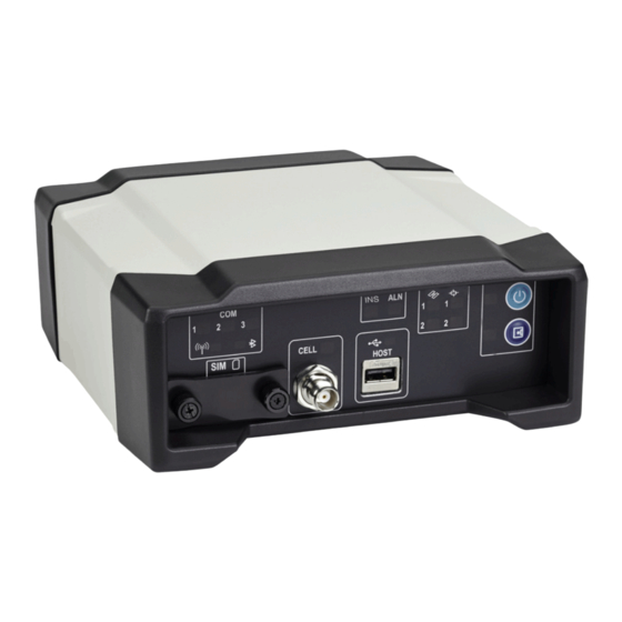
Page 17: Propak6-Front Communication Ports, Buttons And Connectors
HOST Non-cellular Model The Bluetooth/Wi-Fi antennas are located on the front of the ProPak6 (not visible). Refer to Figure 41, Bluetooth/Wi-Fi Antenna Keep-out Area and Antenna Location on page 114 for exact location and keep-out dimensions for this antenna. -
Page 18: Propak6 - Front Label Definitions
Refer to Section 3.1.5, Bluetooth LED on page 36 for details Bluetooth USB Host (Type A) connector - ProPak6 built in USB host with status Memory stick port for automatic downloading of logged data (refer to Section 3.7, Logging and Retrieving Data Overview on page 57) and HOST updating firmware (refer to Section 7.4, Updating Using SoftLoad... - Page 19 Label Description LED Type Push-push style SIM card holder Covered Open Mini-SIM only Remove SIM card holder cover to insert card; replace cover to avoid (25 mm x 15 mm) damaging card ProPak6 Installation and Operation User Manual Rev 4...
-
Page 20: Installation
This chapter contains instructions and tips to install the ProPak6 and create a GNSS receiver system. Additional Equipment Required Refer to Chapter 1, Introduction on page 15 for a list of components included with the Propak6. In order for the receiver to perform optimally, the following additional equipment is required: •... -
Page 21: Propak6 Hardware
01019154 Expansion cable for access to COM7, 8, 9 and 10 as well as CAN1 and CAN2 For more information about the cables used with ProPak6, refer to Section A.5, Cables on page 119. 2.2.2 Selecting a GNSS Antenna An active antenna is required because its Low Noise Amplifier (LNA) boosts the power of the incoming signal to compensate for the line loss between the antenna and the receiver. -
Page 22: Communication With The Propak6
The supply must also be current limited to 6 A with an external fuse. The ProPak6 is supplied with a 12 V power adapter with a built-in 6 A slow blow fuse for use with a standard 12 VDC power outlet. When valid voltage is present at the power supply input, the ProPak6 power LED briefly flashes red and then turns solid green (operational mode). -
Page 23: Standard Configuration Installation
If only one COM port is used, the entire 1.5 A is available to that port. The total peripheral power current is limited to 1.5 A. Transient currents greater than 1.5 A are clamped by the ProPak6. Refer to A.2, ProPak6 Specifications on page 111 for baud rates. Refer to the... -
Page 24: Antenna And External Oscillator Ports
4. The power cable connector (included) is keyed to the PWR 9-36 VDC connector (Figure 6) on the back of the ProPak6. Line up the red dot on the cable with the red line on the connector port and insert. Refer also to Section 3.2.1, Applying Power to the Receiver on page 43. -
Page 25: Dual Antenna Configuration And Installation
7. Connect the ProPak6 to a power source. Once power is detected or activity detected on COM1, COM2 or COM3, the ProPak6 automatically enters Operational mode. The LED beside the button on the front of the ProPak6 briefly turns red and then turns solid green. The ProPak6 is now in Operational mode. The power button is only pressed to turn off the ProPak6. -
Page 26: Typical Dual Antenna Installation
Refer also to Section 2.6.1, Mounting the GNSS Antenna on page 29. 2. Use a coaxial cable (user supplied) to connect an antenna to the TNC ANT1 port and connect a second antenna to the other TNC ANT2 port on the back face of the ProPak6 (Figure 10). ... -
Page 27: Cellular Antenna Installation
3. Insert the power cable connector into the PWR 9-36 V connector (Figure 6) on the back of the ProPak6. Refer to Section 3.2.1, Applying Power to the Receiver on page 43 for details on applying power and power modes. - Page 28 SIM cover will violate ProPak6 IP67 ingress rating. 3. Use a coaxial cable to connect an antenna to the CELL port on the front face of the ProPak6. Specific antenna types are available from NovAtel for the GSM/GPRS/HSDPA version of the ProPak6.
-
Page 29: Mounting The Gnss Antenna
Installation Chapter 2 2.6.1 Mounting the GNSS Antenna The ProPak6 has been designed to operate with any of the NovAtel single-frequency or dual-frequency GNSS antenna models. When installing the antenna system: • Choose an antenna location with a clear view of the sky so that each satellite above the horizon can be tracked without obstruction (refer to Multipath in NovAtel’s book... -
Page 30: Battery Backup
Vehicle Alternator to Vehicle Electrical System Battery Isolator Vehicle Main Auxiliary Battery Battery ProPak6 Installation and Operation User Manual Rev 4... -
Page 31: Connect The Additional Communication Ports On A Propak6
Connect the Additional Communication Ports on a ProPak6 In addition to the three COM ports (COM1, COM2 and COM3/IMU) on the back of the ProPak6, there are four additional COM ports available from the EXP port. To access these ports, connect the ProPak6 Expansion Cable (01019154) to the EXP port. -
Page 32: Connect The Can Bus
API, contact NovAtel Customer Support. The ProPak6 receiver has two CAN Bus ports, CAN1 and CAN2, which are available on the EXP port. To access these signals, use the ProPak6 Expansion Cable (see Figure 13, CAN Bus ports on the ProPak6). -
Page 33: Propak6 Security
Installation Chapter 2 NovAtel Connect is a windows based GUI used to access the receiver's many features without the need for communications protocol or other special software. The Convert utility is a windows based utility used to convert between file formats and strips unwanted records for data file compilation. -
Page 34: Operation
Refer to Section 3.3, Establishing a Receiver COM Connection on page 44 for details. 3.1.3 Status Indicators LED indicators on the front of the ProPak6 provide the status of the receiver. Some LEDs are user configurable and some are fixed. ProPak6 Installation and Operation User Manual Rev 4... -
Page 35: Com Ports Leds
Cell (refer to Section 3.1.9, Cell Port and LED on page 39 for LED states) 3.1.4 COM Ports LEDs The COM LEDs for COM1, 2 and 3 are on the front of the ProPak6. The LEDs indicates if data is in the process of being transmitted or received. Status LED... -
Page 36: Bluetooth Led
Firmware Reference Manual - OM-20000129 for command details. 3.1.6 Wi-Fi LED The Wi-Fi LED lights blue when the ProPak6 is enabled and powered. Refer to Section 5.2, Wi-Fi Network Configuration on page 83 for Wi-Fi details. Status LED LED State... -
Page 37: Satellite Tracking And Positioning Leds
Table 9: Satellite Tracking LEDs States LED State Description Tracking 0 satellites Red (solid) Tracking 1 to 3 satellites Amber (solid) Tracking 4 to 5 satellites Green (solid) Tracking more than 5 satellites ProPak6 Installation and Operation User Manual Rev 4... -
Page 38: Satellite Position Leds States
When a OEM615 is used in a dual antenna configuration, the LED for GNSS2 only shows as off or amber. Both the Satellite Tracking and Satellite Positioning LEDs are user configurable. Refer to the LEDCONFIG command in the OEM6 Firmware Reference Manual (OM-20000129) for details. ProPak6 Installation and Operation User Manual Rev 4... -
Page 39: Cell Port And Led
NovAtel USB drivers are available for Microsoft Windows 2000, Windows XP, Windows Vista and Windows 7 to provide three virtual serial ports over a single USB 2.0 connection using the ProPak6’s USB Device port. The USB drivers are digitally signed and officially supported on Microsoft Windows XP, Windows Vista and Windows 7. -
Page 40: 3.1.11 Ethernet Port
3.1.10.1 USB Host LED The ProPak6 can be configured to manually (default) or automatically download stored data when a memory stick is inserted into the USB Host port (Type A). Refer to Section 3.7.1.3, Manual Retrieval of Logged Data on page 59 for details on configuring the USB Host. -
Page 41: 3.1.12 Icom Ports
Chapter 3 3.1.12 ICOM Ports ICOM ports are virtual ports. The ProPak6 has three shared ICOM ports for Ethernet, Wi-Fi and Cellular. The transport/application layer of the ICOM ports can be configured using Transmission Control Protocol (TCP) for internet IP or User Datagram Protocol (UDP) a slower and less reliable IP protocol. If using TCP, only one connection at a time is supported. -
Page 42: 3.1.14 I/O Port
(OM-20000129) for configuration and command details. 3.1.15 Expansion Port The ProPak6 Expansion port supplies two CAN ports and a USB Host port which is reserved for future use. Refer to Table 17, Expansion Port Pin-Out Description on page 116 for details. -
Page 43: 3.1.16 Antenna Lna Port
LNA power. The ProPak6 provides +5 VDC ±5% at a maximum of 200 mA to the antenna connected to the ANT1 connector. If the ProPak6 is equipped with an ANT2 connector, the second antenna is provided with 5 VDC ±5% at a maximum current of 100 mA. -
Page 44: Establishing A Receiver Com Connection
Chapter 3 Operation 3.2.1.1 Power Down and Reset the ProPak6 If the ProPak6 button is pressed and held for period of time, the receiver shuts down or resets. Button Press Time Result LEDs Press and hold minimum Power to the ProPak6 is turned off... -
Page 45: Communicating With The Receiver Using Novatel Connect
RXSTATUSEVENTA log ONNEW on all ports. See Section 8.4 RXSTATUSEVENT Log on page 107 for more details. 2. If NovAtel Connect is unable to locate the ProPak6 receiver, use a different COM port to com- municate with the receiver. When communication has been established, issue a... -
Page 46: Transmitting And Receiving Corrections
Use a ProPak6 receiver for the Rover Station Use a ProPak6 receiver for the Base Station 1. Connection a GNSS antenna 1. Connection a GNSS antenna 2. Connect a computer to COM1 2. Connect a computer to COM1 for setup and monitoring 3. -
Page 47: Defining Antenna And Base Antenna
The base and rover stations can both be NovAtel receivers, however NovAtel receivers will work with some other brands. Contact Customer Support for further details (refer to Customer Support on page 8 for details). - Page 48 10 1 (optional) saveconfi (optional) NOVATELX interfacemode com2 none novatelx off fix position lat lon hgt (enter your own lat, lon, hgt) log com2 novatelxobs ontime 1 saveconfig (optional) ProPak6 Installation and Operation User Manual Rev 4...
-
Page 49: Rover Station Configuration
NOVATELX none off External ALIGN Master or Rover Configuration Only The ProPak6 product is a dual card enclosure that can provide an ALIGN solution without additional receivers. This section is for applications that require additional rover receivers. -
Page 50: Pdp And Glide ™ Configurations
The effect is especially evident when a receiver transitions from an RTK position mode solution to a lower accuracy “fall back” solution, such as NovAtel CORRECT PPP, DGPS, WAAS+GLIDE or even autonomous GLIDE (see Figure 16, Positioning Change Without Steadyline). -
Page 51: Maintain
This time period is specified by the Transition time parameter in the STEADYLINE command. Figure 18: Steadyline Transition Position Intended Path change to change to lower accuracy higher accuracy solution solution ProPak6 Installation and Operation User Manual Rev 4... -
Page 52: Prefer Accuracy
Figure 20, Steadyline UAL- Warning Limit Example on page 53 and Figure 21, Steadyline UAL - Out of Bounds Example on page 53 show an examples of Steadyline using the UAL mode. ProPak6 Installation and Operation User Manual Rev 4... -
Page 53: Steadyline Ual- Warning Limit Example
The solution accuracy exceeds the operational limit. The position type changes to WARNING. The Steadyline mode changes from Maintain to Transition. The solution accuracy exceeds the warning limit. The position type changes to OUT_OF_BOUNDS. Steadyline is disabled. ProPak6 Installation and Operation User Manual Rev 4... -
Page 54: Configuration Notes
NOVATEL and log out variants of the standard correction messages with a NovAtel header. ASCII or binary variants can be requested by appending an A or B to the standard message name. For example, on the base station: interfacemode com2 novatel novatel fix position 51.11358042 -114.04358013 1059.4105... -
Page 55: Enabling L-Band
Near shore applications are defined as vessels operating within 10 km of shore. To obtain a subscription, contact your local NovAtel sales representative or visit www.novatel.com/products/terrastar-gnss- corrections. The receiver’s TerraStar Product Activation Code (PAC) or the NovAtel product serial number (PSN) is needed to obtain a subscription. To obtain the receiver-specific PAC, enter the following command:... - Page 56 A subscription is required to use the OmniSTAR service. To obtain a subscription, contact OmniSTAR at 1-888-883-8476 or 713-785-5850. Provide the receiver’s OmniSTAR serial number (which is different from the NovAtel serial number). To obtain the OmniSTAR serial number, enter the following command: log lbandinfo The log displays the L-Band serial number in the fifth field following the log header.
-
Page 57: Logging And Retrieving Data Overview
Refer to the following sections for detailed instructions on performing logging tasks. Naming Log Files File names for logs saved to onboard storage can be specified manually or the ProPak6 can be set to automatically name files. Manual Log File Naming Use NovAtel Connect or HyperTerminal to name logged files. -
Page 58: Onboard Data Storage
3.7.1 Onboard Data Storage The ProPak6 contains 4 GB of memory for onboard data storage. Data can be logged to internal memory and downloaded for post-processing in a variety of ways. To begin logging: •... - Page 59 LOG FILE RANGEB ONTIME 1 LOG FILE BESTPOSB ONTIME 1 3.7.1.3 Manual Retrieval of Logged Data By default, files can be copied from the ProPak6 USB Host port (Type A) to a USB stick using DOSCMD COPY command. Example: DOSCMD COPY MYFILE 3.7.1.4...
-
Page 60: Reading Data And Post-Processing
3.7.2 Reading Data and Post-Processing Logs can be directed to any of the ProPak6 communication ports and can be automatically generated when new or changed data becomes available or at regular intervals. Example: LOG BESTPOSA ONTIME 1 Data can be collected through NovAtel Connect using the Logging Control Window. -
Page 61: Pass-Through Logging
ProPak6 Web UI. 1. Ethernet DHCP is the default network setup for Internet access for the ProPak6. If a Static IP is required, refer to Section 4.2, Static IP Address Configuration on page 73. Refer to Section 5.2, Wi-Fi Network Configuration on page 83 or Section 5.3, Cellular Activation GSM/GPRS/HSDPA on... - Page 62 8. Press the Log In button. The default Product Information home page displays, This page contains information about the connected ProPak6 receiver. Note, it may take a few moments to load all information into the fields. ProPak6 Installation and Operation User Manual Rev 4...
-
Page 63: Product Information (Info)
Shows IP status The blinking light Color Status indicates receiver connection alive status Error Green Good Press the button, in the upper right corner, to display Yellow Warning additional information and configuration options. ProPak6 Installation and Operation User Manual Rev 4... -
Page 64: Device Menu
Info Refer to Figure 22, Product Information (Info) on Page 63 for location. 3.8.2.2 Update Use to update either the firmware on the ProPak6 or the Web UI interface. Click to move between options ProPak6 Installation and Operation User Manual Rev 4... -
Page 65: Dashboard
Each shape also displays the PRN of that satellite. Click a shape, within the Constellation circle, to display SV information. No signal match Blue No ephemeris Yellow No ambiguity Teal All other health status Orange ProPak6 Installation and Operation User Manual Rev 4... - Page 66 Displays the amount of memory available, amount used, available space and time left along with a list for files including size and date modified on the ProPak6. Click on one or multiple check boxes and press the delete button to delete selected files. Click on the up/down arrows at the top of each column to customize the sort order.
- Page 67 L-Band Beam and the system will begin converging a PPP solution. Note that this can take approximately 15-20 minutes to complete. Clicking another beam from the beam table and clicking 'Assign L-Band Beam' will manually assign the beam selected. ProPak6 Installation and Operation User Manual Rev 4...
- Page 68 Customer Support (support@novatel.com) to inquire about TerraStar subscription activation. For beam coverage information, visit www.terrastar.net/coverage.html. Use the Differential page to configure the receiver for Base/Rover operations. The NovAtel Connect PC Utilities contain a number of additional utilities that can be used to access more advanced features of the ProPak6. ...
- Page 69 Up to 9 profiles can be stored on the ProPak6 and 20 commands per profile. Profile restrictions are each command in a profile cannot exceed 200 characters and a maximum of 1500 characters for all commands in one profile.
-
Page 70: Terminal
Load Button Create a text file containing a list of commands to be executed in sequence. Name and save the file to the connected computer/device (not the ProPak6). Use the Load button to find and select one of these files. - Page 71 Press the Save button to name and create a file of any logged data. Logged data files are listed under the Storage menu. Use the Cancel button to return to the Terminal page without saving. ProPak6 Installation and Operation User Manual Rev 4...
- Page 72 A maximum of 15000 responses can be recorded in one session using the Rec feature. Refer to Section 3.8.3.6, Profile Manager on page 69 if intending to log data over a long period of time. ProPak6 Installation and Operation User Manual Rev 4...
-
Page 73: Ethernet Configuration
TCP/IP is used for the connection in this simple network. This configuration can also be used in a bench test environment to confirm Ethernet functionality. By default, the ProPak6 is set to Ethernet DHCP Dynamic IP address. -
Page 74: Static Ip Address Configuration-Receiver
Static IP Address Configuration—Receiver Follow these steps to set up a static IP address on the ProPak6 receiver: 1. Connect a computer to the ProPak6 receiver using a null modem serial cable or USB cable or use Bluetooth or Wi-Fi. -
Page 75: Static Ip Address Configuration-Windows Xp With Sp3
Ensure the Ethernet settings used for the computer are compatible with the Ethernet settings on the ProPak6 receiver. For example, the following settings are compatible with the ProPak6 receiver settings used in Section 4.2.1 Static IP Address Configuration—Receiver on page 74: ip address = 192.168.74.11... -
Page 76: Confirming Ethernet Setup
2. Connect to the receiver using NovAtel Connect or any third party terminal program that supports TCP/IP connections. Use the static IP address and port number assigned to the ProPak6 receiver in Section 4.2.1 Static IP Address Configuration—Receiver on page 74. -
Page 77: Dynamic Ip Address Configuration
IP addresses to the OEM6 receiver, based on its predetermined available IP addresses. To set up a dynamic IP address configuration, follow these steps: 1. For first time configuration, connect a computer to the ProPak6 receiver using a null modem serial cable or USB cable. -
Page 78: Base/Rover Configuration Through Ethernet Connectivity
Chapter 4 Ethernet Configuration 4. Obtain the IP address assigned to the ProPak6 receiver by the DHCP server. log ipstatus once Make a note of the IP address returned with this log. This value is used later in this procedure. -
Page 79: Base/Rover Ethernet Setup-Propak6
Quick Start Guide for the product or NovAtel Connect Help. 3. Connect the power cables to both of the ProPak6 receivers and apply power to the receivers. 4. Connect the Ethernet cables to the Ethernet ports on both ProPak6 receivers. - Page 80 SAVEETHERNETDATA ETHA command is not applicable to the ICOMCONFIG and NTRIPCONFIG settings. The SAVEETHERNETDATA ETHA command overrides the SAVECONFIG command configuration settings. The FRESET command does not clear Ethernet setting; FRESET INTERNET must be issued. ProPak6 Installation and Operation User Manual 4...
-
Page 81: Radio Configuration And Activation
ProPak6 (paired). Only one incoming Bluetooth connection is supported at a time by the ProPak6. A maximum of 16 devices can be paired with the ProPak6. Refer to Section 3.1.5, Bluetooth LED on page 36 for status LED information. - Page 82 The New Connection window of NovAtel Connect can also be used. Once the COM port is determined, connect to the device over this port.
-
Page 83: Wi-Fi Network Configuration
If the ProPak6 is not to be accessible to a LAN or is located in a remote location that does not have an AP nearby, configure the ProPak6 as the AP. When configured as the AP, the ProPak6 must use a static IP address, although any devices connecting to the ProPak6 (mobile phone, laptop, etc.) can use either... -
Page 84: Wi-Fi Ap Configuration
By default, the ProPak6 Wi-Fi radio is configured as an AP and is enabled. If a ProPak6 is changed from the default AP to a Client configuration and later needs to return to an AP configuration, the WIFIAPCONFIG MODE AP command is issued and the Wi-Fi module power cycled (see step 9 below). - Page 85 The first three numbers of the IP should match the receiver • To avoid IP conflicts between the static IP address of the Client and the IP of the ProPak6, set the static IP address of the client to 192.168.1.5 or above •...
-
Page 86: Wi-Fi Client Configuration
5.2.2.1 Multiple AP Configurations Up to four APs can be configured on the ProPak6. Each AP supports up to 5 Client associations at one time. The default mode is AP1. Default value settings for AP2, AP3 and AP4 are blank. -
Page 87: Wi-Fi Scanning
The IP address of the primary DNS server. (If not using DHCP.) (for example: 10.0.0.3) 2. Connect the ProPak6 to a computer using one of the communication ports and turn power on. 5.2.4 Wi-Fi Scanning Wi-Fi scanning is performed before connecting to either an Open/Encrypted, DHCP/Static network. - Page 88 12. Issue the SAVECONFIG command to save the configuration Non-Volatile Memory (NVM) 13. Issue the WIFICLICONTROL APPLYCONFIG command to save settings Once Wi-Fi is connected, the ProPak6 Client is accessible on the LAN. To use Wi-Fi as the primary internet access point, issue the SETPREFERREDNETIF WIFI ...
-
Page 89: Cellular Activation Gsm/Gprs/Hsdpa
LED information. 5.3.1 Configure Cellular as the Network Default Ethernet (ETHA) is the default network for internet access for the ProPak6. The default network can be changed to Cellular by issuing the SETPREFERREDNETIF CELL command. Refer to the OEM6 Firmware Reference Manual (OM-20000129) for additional command details. -
Page 90: Sim Card Installation
Failure to properly secure SIM cover will violate ProPak6 IP67 ingress rating. 4. Ensure a cellular antenna is connected to the ProPak6 and turn the ProPak6 power on. 5. LOG CELLULARSTATUS ONCHANGED to display the modem and cellular connection status. -
Page 91: Eject A Sim Card
Issue the CELLULARCONFIG POWER ON command to turn the cellular radio on. Airplane Mode Enabling Airplane Mode turns off any Wi-Fi, Bluetooth or cellular radios in the ProPak6. Airplane Mode is disabled by default (radios on). If Airplane mode is enabled and then disabled, all radios automatically return to their last state (on or off) however, any connections made before airplane mode was enabled are not restored. -
Page 92: Ntrip Configuration
Network Transport of RTCM via Internet Protocol (NTRIP) is an application protocol used to stream GNSS differential correction data over the Internet. Configure an ProPak6 receiver as either an NTRIP server or an NTRIP client. For more information about NovAtel’s NTRIP, refer to our NTRIP Product Sheet on our website at www.novatel.com/products/... - Page 93 The following is an NTRIP Client configuration example without the use of a Network RTK system: INTERFACEMODE NCOM1 RTCA NONE OFF RTKSOURCE AUTO ANY PSRDIFFSOURCE AUTO ANY LOG BESTPOS ONTIME 1 (optional) SETPREFERREDNETIF <WIFI> or <CELL> or <ETHA> SAVECONFIG ProPak6 Installation and Operation User Manual Rev 4...
- Page 94 Chapter 6 NTRIP Configuration ProPak6 Installation and Operation User Manual Rev 4...
-
Page 95: Novatel Firmware And Software
WinLoad software utility WinLoad and SoftLoad instructions follow. Firmware Updates and Model Upgrades A local NovAtel dealer can provide all the information needed to upgrade or update a receiver. Refer to www.novatel.com/where-to-buy for contact information or contact sales@novatel.com support@novatel.com directly. -
Page 96: Model Upgrades
NovAtel Firmware and Software 7.1.2 Model Upgrades Model upgrades enable purchased receiver features. Contact a local NovAtel dealer to assist in selecting the upgrade options that best suit your GNSS needs at www.novatel.com/where-to-buy. Contact NovAtel Customer Support www.novatel.com/support NovAtel Sales to request a temporary upgrade authorization code for trial purposes. -
Page 97: Updating Or Upgrading Using The Winload Utility
NovAtel Firmware and Software Chapter 7 Temporary auth-codes may be provided by NovAtel for evaluation purposes. Once the trial period has expired, a new auth-code will need to be obtained from NovAtel Customer Support (support@novatel.com). The new download package includes a signed firmware file type that uses an extension designated as “.shex”... -
Page 98: Using The Winload Utility
Com Port drop down list and the baud rate from the Download Baudrate drop down list. Set the baud rate as high as possible (the default of 115200 is preferred if a higher baud rate is not available). Figure 32: COM Port Setup ProPak6 Installation and Operation User Manual Rev 4... -
Page 99: Updating Using Softload Commands
The receiver stops tracking GNSS satellites during the SoftLoad process. Do not attempt to SoftLoad when GNSS satellite tracking on the unit is required. If the unit is connected to the NovAtel Connect utility, only the Console and ASCII Message windows may remain open in the Connect Utility. -
Page 100: Working With S-Records
Length.This is the hexadecimal number of character pairs to follow in the record. This value minus 4 bytes for the address and 1 byte for the check sum is copied into the "data length" field SOFTLOADDATA of the command Header ProPak6 Installation and Operation User Manual Rev 4... -
Page 101: Sending Firmware Data
SOFTLOADDATA command. The *.hex and *.shex file data may contain many gaps and jumps. For example, in many NovAtel *.hex and *.shex files, data for address 0x000_00000 is stored near the very end of the file. Example Packaging Multiple S3 Records In A SOFTLOADDATA Command... -
Page 102: Softload Update Method
SOFTLOADDATA Add data to existing command SOFTLOADDATA command must be sent as a NovAtel binary format command. 7.4.4 SoftLoad Update Method This section describes the sequence of commands that are issued to the receiver when updating using a *.hex or *.shex file. - Page 103 The SoftLoad process can be safely canceled at any time using the SOFTLOADRESET command or by otherwise resetting the receiver. Once the COMPLETE status is reported by SOFTLOADSTATUS, the new firmware image will be run after the receiver is reset. ProPak6 Installation and Operation User Manual Rev 4...
-
Page 104: Firmware Update Using Ftp Or Usb Mass Storage Device
6. Reset the receiver using any of the following methods: A. Enter the RESET command B. Enter the FRESET command C. Power-cycle the receiver 7. Once the receiver resets, the new version of firmware is active. ProPak6 Installation and Operation User Manual Rev 4... -
Page 105: Softload Errors
(unlocks) model features. This command only functions with a valid auth-code assigned by NovAtel Customer Support. The upgrade can be performed directly through the NovAtel Connect command line or from any other communications program. Refer to the Format of Firmware Files section on Page 97 for details on updating versus upgrading. -
Page 106: Built-In Status Tests
Use the masks to specify whether various status fields generate errors or event messages when set or cleared. Refer to the RXSTATUS log, RXSTATUSEVENT log and STATUSCONFIG command in the OEM6 Family Firmware Reference Manual for more detailed descriptions of these messages. ProPak6 Installation and Operation User Manual Rev 4... -
Page 107: Error Strobe Signal
If the receiver status word indicates a problem, see Resolving an Error in the Receiver Status Word table in the troubleshooting section of the OEM6 Family Installation and Operation User Manual (OM-20000128). ProPak6 Installation and Operation User Manual Rev 4... -
Page 108: Error Word
Each bit, in any mask, operates on the bit in the same position in the status word. For example, setting bit 3 in the priority mask changes the priority of bit 3 in the status word. ProPak6 Installation and Operation User Manual Rev 4... -
Page 109: Receiver Status Code
1 to a 0 state. Note the error word does not have any associated mask words. Any bit set in the error word results in a RXSTATUSEVENT log broadcast (unless unlogged). Refer also to the RXSTATUS log in the OEM6 Family Firmware Reference Manual (OM-20000129) for a more detailed description. ProPak6 Installation and Operation User Manual Rev 4... -
Page 110: A Technical Specifications
GPS-only. www.novatel.com/products/novatel- c. Requires a TerraStar subscription which is available direct from NovAtel correct-ppp d. Performance dependent on local observing conditions. e. Time accuracy does not include biases due to RF or antenna delay. -
Page 111: A.2 Propak6 Specifications
MIL-STD-810G, 516.6, Procedure 1, 40 g 11 ms terminal sawtooth Acceleration MIL-STD-810G, Method 513.6, Procedure II (operational) 16 g a. See also the Notice section of this manual starting on page 9. ProPak6 Installation and Operation User Manual Rev 4... - Page 112 Frequency Range 850 to 1900 MHz Depending by frequency band(s) provided by the network operator. Use the most suitable antenna for the band(s). NovAtel recommends the accessory ANT GSM/HSPA LP 3 / 4 dBi NMO MTG antenna – P/N 12023303 Bandwidth...
-
Page 113: A.3 Dimension Drawings
A.3 Dimension Drawings Figure 40: ProPak6 Dimensions Dimensions are in millimeters ProPak6 Installation and Operation User Manual Rev 4... -
Page 114: Bluetooth/Wi-Fi Antenna Keep-Out Area And Antenna Location
Figure 41: Bluetooth/Wi-Fi Antenna Keep-out Area and Antenna Location Keep-out 20 cm from Bluetooth/Wi-Fi antenna. Dimensions are in millimeters ProPak6 Installation and Operation User Manual Rev 4... -
Page 115: Com1 And Com2 Port Pin-Out Descriptions
RS-232 Mode RS-422 Mode IMU_EVENT_OUT(SYNC)1 IMU_EVENT_OUT(SYNC)1 RX(+) TX(+) TX(-) RX(-) reserved reserved a. The IMU_EVENT_OUT(SYNC)1 signal can be disabled. Refer to Figure 7, Ethernet, COM or USB Device Ports on page 24. ProPak6 Installation and Operation User Manual Rev 4... -
Page 116: Expansion Port Pin-Out Description
Table 17: Expansion Port Pin-Out Description Connector Pin No. Signal CAN1+ CAN1- CAN2+ CAN2- DGND VBUS USB (D-) USB (D+) DGND Shell DGND Refer to Figure 8, Expansion and I/O Ports on page 25. ProPak6 Installation and Operation User Manual Rev 4... -
Page 117: Propak6 Strobe Electrical Specifications
(Mark2) Event_In3 (Mark3) Event_In4 (Mark4) VCC = 3.3 V; 85C VCC = 3.3 V; 85C VARF VCC = 3.3 V; 85C RESETIN VCC = 3.3 V; 85C VCC = 3.3 V; 85C ProPak6 Installation and Operation User Manual Rev 4... -
Page 118: Oem615 Receiver Card Performance For Propak6 (Model Dependent)
GPS-only. c. Time accuracy does not include biases due to RF or antenna delay. d. L2 P for GLONASS e. L2 C/A for GLONASS f. In accordance with export licensing. ProPak6 Installation and Operation User Manual Rev 4... -
Page 119: A.5 Cables
A.5.1 12 V Power Adapter Cable (NovAtel part number 01017663) The power adapter cable supplied with the ProPak6, provides a convenient means for supplying +12 V DC while operating in the field. Input is provided through the standard 12V power outlet. The output from the power adapter utilizes a 4- pin LEMO connector (LEMO part number FGG.0B.304.CLAD52Z) and plugs directly into the PWR input... -
Page 120: Wiring Table
Null-modem Cable (NovAtel part number 01017658) This cable supplied with the ProPak6, provides an easy means of communications with a PC/laptop. The cable is equipped with a 9-pin connector at the receiver end which can be plugged into the COM1, COM2, or AUX port. - Page 121 Straight Through Serial Cable (NovAtel part number 01018520) This cable can be used to connect the ProPak6 to a modem or radio transmitter to propagate differential corrections. The cable is equipped with a female DB9 connector at the receiver end. The male DB9 connector at the other end is provided to plug into your user-supplied equipment (please refer to your modem or radio transmitter user guide for more information on its connectors).
-
Page 122: I/O Cable Wiring Instructions
I/O Cable (NovAtel part number 01018519, 01019148) These cables can be used to connect the ProPak6 I/O port. The cables are 2 metres in length, with a DB9 male connector at one end and tinned and tagged conductors at the other. -
Page 123: Propak6 Expansion Cable Pin-Out Descriptions
A.5.5 ProPak6 Expansion Cable (NovAtel part number 01019154) The optional cable 01019154 provides access to the COM7, COM8, COM9, COM10, CAN1 and CAN2 ports. COM4, COM5 and COM6 are used internally on the ProPak6. COM7 COM8 COM9 COM10 Dimensions are in millimetres. -
Page 124: P2 Connector Pin-Out Descriptions
Table 22: P2 Connector Pin-Out Descriptions Description No connect Transmit Data (TXD) Receive Data (RXD) No connect Ground (GND) No connect Clear To Send (CTS) Request To Send (RTS) No connect Shell Ground (GND) ProPak6 Installation and Operation User Manual Rev 4... -
Page 125: B Replacement Parts
Appendix B Replacement Parts The following are a list of the replacement parts available for your NovAtel ProPak6 receiver. Should you require assistance, or need to order additional components, please contact your local NovAtel dealer or Customer Service representative. B.1 ProPak6... -
Page 126: B.3 Manufacturer's Part Number
The following original manufacturer’s part number is provided for information only and is not available from NovAtel as a separate part: Product Part Description Company Part Number ProPak6 Power Cable 4-pin socket connector LEMO FGG.0B.304.CLAD52Z connector ProPak6 Expansion Port 9-pin socked connector LEMO FGA.OB.309.CLAZ connector ProPak6 Installation and Operation User Manual Rev 4... -
Page 127: Frequently Asked Questions
The ProPak6 can be configured as both a Access Point (AP) or a Client. So by default, the unit is not assigned an IP address. However, once an IP address is assigned to the receiver, it is preserved through issuing the SAVECONFIG command so the IP address is retained if the ProPak6 is powered down (refer to theWi-Fi Network Configuration on page 83 for details). - Page 128 STATE OFF command and then issue the WIFICONFIG STATE ENABLED command. My network keeps defaulting to Wi-Fi, why? Ethernet is the ProPak6 default network primarily used for internet access. It can be changed to either Wi-Fi or Cellular as needed by issuing: SETPREFERREDNETIF <ETHA>, <CELL>...
- Page 129 If done incorrectly, changing the Windows Registry may impair the operation of the computer. Editing the Windows Registry is for advanced Microsoft Windows users only. NovAtel Inc. is not able to provide any technical support for any actions taken regarding information found in Microsoft’s Knowledge Base.
- Page 130 OM-20000148 Rev 4 September 2015...
Need help?
Do you have a question about the ProPak6 and is the answer not in the manual?
Questions and answers