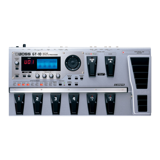
Boss GT-10 Owner's Manual
Guitar effects processor
Hide thumbs
Also See for GT-10:
- Workshop manual (20 pages) ,
- Training manual (10 pages) ,
- Turbostart (2 pages)
Table of Contents
Advertisement
Quick Links
Owner's Manual
Thank you, and congratulations on your choice of the BOSS GT-10.
201b
Before using this unit, carefully read the sections entitled: "USING THE UNIT SAFELY" (p.
2–3), and "IMPORTANT NOTES" (p. 4–5). These sections provide important information
concerning the proper operation of the unit. Additionally, in order to feel assured that you
have gained a good grasp of every feature provided by your new unit, Owner's manual
should be read in its entirety. The manual should be saved and kept on hand as a conve-
nient reference.
202
Copyright © 2008 BOSS CORPORATION
All rights reserved. No part of this publication may be reproduced in any form without the
written permission of BOSS CORPORATION.
Advertisement
Table of Contents

Related Manuals for Boss GT-10


Summary of Contents for Boss GT-10
- Page 1 Owner’s Manual Thank you, and congratulations on your choice of the BOSS GT-10. 201b Before using this unit, carefully read the sections entitled: “USING THE UNIT SAFELY” (p. 2–3), and “IMPORTANT NOTES” (p. 4–5). These sections provide important information concerning the proper operation of the unit. Additionally, in order to feel assured that you have gained a good grasp of every feature provided by your new unit, Owner’s manual...
- Page 2 USING THE UNIT SAFELY symbol alerts the user to important instructions Used for instructions intended to alert or warnings.The specific meaning of the symbol is the user to the risk of death or severe determined by the design contained within the injury should unit...
- Page 3 012b 101b • Immediately turn the power off, remove the AC • The unit and the AC adaptor should be located so adaptor from the outlet, and request servicing by their location or position does not interfere with your retailer, the nearest Roland Service Center, their proper ventilation.
-
Page 4: Important Notes
IMPORTANT NOTES Power Supply Maintenance 401a • Do not connect this unit to same electrical outlet that is • For everyday cleaning wipe the unit with a soft, dry cloth being used by an electrical appliance that is controlled by or one that has been slightly dampened with water. - Page 5 Printing Conventions and • Use only the specified expression pedal (Roland EV-5, icons in This Manual BOSS FV-500L/500H with a connection cable (stereo 1/4” phone – stereo 1/4” phone); sold separately). By connecting any other expression pedals, you risk causing Text or numerals enclosed Indicate buttons.
-
Page 6: Table Of Contents
Contents IMPORTANT NOTES ................4 Main Features..................10 Names of Things and What They Do...........11 Front Panel..............................11 Rear Panel ..............................13 Quick Guide...................14 Getting Ready ............................14 Playing Sounds ............................16 Editing................................ 18 Basic Operation..........................18 Creating Sounds Based on Existing Patches ................18 Creating Sounds with Ease ........................ - Page 7 Chapter 3 Saving a Tone ..............42 Saving a Patch (PATCH WRITE) ......................42 Copying Patches (PATCH COPY) ......................42 Exchanging Patches (PATCH EXCHANGE)..................43 Initializing Patches (PATCH INITIALIZE)................... 43 Storing Settings by Effect (User Quick Settings).................. 44 Copying or Swapping PREAMP Settings Between Channels ............45 Chapter 4 Playing Sounds ..............46 Setting the Functions of the Knobs of the Play Screen................
- Page 8 Sending External EXP Pedal Operations as Control Change Messages ....... 82 Sending CTL Pedal Operations as Control Change Messages ..........83 Sending External Footswitch Operations as Control Change Messages ......83 Setting the Correspondences Between Program Change Messages and Patches (Program Change Map) ...........................
- Page 9 PAN............................... 115 SLICER............................116 VIBRATO............................116 RING MOD. (Ring Modulator) ....................117 HUMANIZER..........................117 2X2 CHORUS..........................118 SUB DELAY ..........................118 DELAY ..............................119 DELAY Common Parameters ....................119 Pan..............................120 Dual-S, Dual-P, Dual-L/R......................120 Warp.............................. 120 Modulate ............................120 CHORUS..............................
-
Page 10: Main Features
Newer, More Powerful BOSS COSM Effects Totally new effects made possible by an original, high-performance processor that relies on the latest BOSS technology. Utilizing COSM technology that transcends the realm of mere modeling, these effects achieve sounds with an even more natural performance feel and richer expressiveness than previous designs. -
Page 11: Names Of Things And What They Do
Names of Things and What They Do Front Panel 1. Display 8. EFFECTS SELECT Various information about the GT-10 is shown here. The Use these buttons to switch effects on or off, or to change display screen on the left side shows the bank number. their settings (p. - Page 12 Names of Things and What They Do 12. CATEGORY/ENTER Button Use this button for the following operations: • When executing an operation • When selecting patches arranged by category (p. 31) • When doing tap input for MASTER BPM (p. 122) or Delay Time (p. 119) 13.
-
Page 13: Rear Panel
6. EXP PEDAL/CTL 3, 4 Jack Connect an optional expression pedal (such as the Roland EV-5) or footswitch (such as the BOSS FS-6) here (p. 22). 7. USB Connector Use a USB cable to connect a computer to this connector and enable exchange of data between the GT-10 and the computer (p. -
Page 14: Quick Guide
Quick Guide The Quick Guide describes required settings and basic operations. For detailed descriptions of operations, refer to the explanations in chapter 1 and after. Getting Ready Connect the Guitar and Amp 1. Connect the guitar and the guitar amp. Before turning on the power, confirm the following. - Page 15 Quick Guide Examples of Connections Using Adjust the Volume the SEND/RETURN Jacks Example 1: Using an External Effects Unit Use the OUTPUT LEVEL knob to adjust the volume level. This enables use as one of the GT-10’s effects. Guitar Amp Guitar External Effects INPUT...
-
Page 16: Playing Sounds
Quick Guide Playing Sounds Once you’ve finished getting ready to play, try playing sounds as you operate the GT-10. About the Bank and Number Display Choosing a Patch in the Current Bank The display on the left side shows the bank, and the display on the right side shows the Choose the patch you want to use by bank and patch number. - Page 17 Quick Guide Switch the Patch with the Dial When you’re at the Play screen (p. 23), turning the dial switches the patch. Working with Effects Using the Pedals The EXP Pedal and the CTL 1 and 2 pedals can be set to use in switching effects on or off for individual patches, use as a volume pedal, and other such operations.
-
Page 18: Editing
Quick Guide Editing Basic Operation This describes the basic operations you use when editing settings. Access the System Menu Choose the menu item. The setting screen for the selected screen. item appears. * If you want to next menu item further, repeat Steps 2 and 3. - Page 19 Quick Guide Change the parameter settings. Quit the settings. (Go back to the previous screen.) Example 1 Example 2 Each press this button switches between Knob View and List View. Only the major parameters are shown in Knob View, you can adjust the parameters quickly.
-
Page 20: Creating Sounds With Ease
Quick Guide Creating Sounds with Ease Using the EZ Tone feature (p. 32) lets you quickly find settings close to the musical genre and feel of the song you want to create, and enables you to create the sound easily. Let’s try creating sounds using EZ Tone. - Page 21 Quick Guide Adjust the Distortion Adjust the Other Effects Using Tone Grid, adjust the effects until Using Tone Grid, adjust the distortion you get the sound you want. until you get the sound you want. Ex. When you adjust the Delay Delay sound: Wet (strong) For solos Cursor movement Cursor movement...
-
Page 22: Chapter 1 Playing Sounds
When outputting in mono, connect the cable to the OUTPUT L/MONO jack. • Use only the specified expression pedal (Roland EV-5 or BOSS FV-500L; • When connecting a BOSS FS-6 footswitch (optional) to the EXP PEDAL 2/ sold separately). By connecting any other expression pedals, you risk CTL 3,4 jack, set the MODE switch and POLARITY switch as shown below. -
Page 23: Turning On The Power
Chapter 1 Playing Sounds Turning on the Power Before turning on the power, confirm the following. • Are all external devices properly connected? • Is the volume on the GT-10, your amp, and all other connected devices turned down to the minimum level? Once the connections have been completed, turn on power to your various devices in the order specified. -
Page 24: Switching The Play Screen
Chapter 1 Playing Sounds Switching the Play Screen The GT-10 has a variety of Play screen variations. You can switch the information shown in the Play screen by pressing • You can use the PARAMETER knobs 1 through 4 to work with the values of the parameters displayed at the bottom of the Play screen. Also, for each parameter, you can change the corresponding assignment at the SYS KNOB ASSIGN screen (p. -
Page 25: Making Settings For A Connected Device (Output Select)
Chapter 1 Playing Sounds Making Settings for a Connected Device (Output Select) Select the type of device connected to the OUTPUT jack. To derive the maximum performance from the GT-10, be sure to make the correct setting for OUTPUT SELECT, the one that’s most suitable for your setup. •... -
Page 26: Turning Off The Power
Chapter 1 Playing Sounds Turning Off the Power Before turning off the power, confirm the following. • Is the volume on the GT-10, your amp, and all other connected devices turned down to the minimum level? 1. Turn off the power to the guitar amp (power amp) → any external effects processors and other devices. -
Page 27: How To Tune
Chapter 1 Playing Sounds How to Tune 1. Play a single open The Note Name closest to the pitch of the note on the string string that was played appears in the Only play a single note on the one string being tuned. display. -
Page 28: Changing The Tuner Settings (Tuner Out)
Chapter 1 Playing Sounds Changing the Tuner Settings (Tuner Out) Turn on the Tuner. Move the cursor to OUTPUT. Select the output while Tuner is on. • When OUTPUT is set to “Bypass,” and Tuner is set to ON, you can adjust the volume of the direct sound by operating the EXP Pedal. -
Page 29: Selecting A Tone (Patch Change)
Chapter 1 Playing Sounds Selecting a Tone (Patch Change) What is a Patch? A combination (or set) of effects together with a group of parameter settings is called a “patch.” The GT-10 can store 400 different patches in memory, organized by bank and number as shown below. fig.02-010 Preset Bank 50 Preset Bank 01... -
Page 30: Using The Pedal To Select The Patch
Chapter 1 Playing Sounds Using the Pedal to Select the Patch Patches are switched by selecting a “bank” (U01–U50, P01–P50) and “number” (1-4). The bank and number appear in the GT-10’s display as shown in the following figure. fig.02-040d Bank Number Bank fig.02-050... -
Page 31: Using The Dial To Select The Patch
Chapter 1 Playing Sounds Using the Dial to Select the Patch On the GT-10, you cannot switch patches in any Select the Patch. screen other than the Play screen. Press [EXIT] to return to the Play screen (p. 24). Separating Patches into Groups (CATEGORY) The GT-10 includes a function that allows you to categorize patches into a number of different groups. -
Page 32: Chapter 2 Creating Sounds (Patch Edit)
Chapter 2 Creating Sounds (Patch Edit) Creating Sounds with Ease (EZ TONE) Creating a Tone for the Song You Envision (Create) If you already have a clear idea about the kind of sound you want to create, you can save yourself a lot of trouble by starting out with a patch that is relatively similar to what you have in mind, then tweak its settings until you arrive at what you want. -
Page 33: Adjusting The Tone (Edit)
Chapter 2 Creating Sounds (Patch Edit) Adjusting the Tone (Edit) By using EZ TONE EDIT you can adjust the sound of a patch with ease, without having to manipulate complicated parameters. The EZ TONE EDIT screen appears. P1 knob: Adjusts the distortion (DRIVE). P2 knob: Adjusts the delay time. -
Page 34: Setting The Effects
Chapter 2 Creating Sounds (Patch Edit) Setting the Effects Turning an Effect On and Off The GT-10’s internal effects are switched on and off with button controls. When an effect is switched on, the button's indicator lights up; the indicator goes out when the effect is off. [MASTER/PEDAL FX] does not light up. -
Page 35: Setting The Effects Simply (Quick Setting)
Chapter 2 Creating Sounds (Patch Edit) Setting the Effects Simply (Quick Setting) Each effect includes prepared sample settings called “Quick Settings.” You can easily create new effect sounds just by selecting and combining these Quick Settings. The setting screen for the effects appears. •... -
Page 36: Adjusting The Parameters
Chapter 2 Creating Sounds (Patch Edit) Adjusting the Parameters Each effect comprises several different kinds of parameters. You can more precisely create the sounds you want by editing each of these parameters individually. The setting screen for the effects appears. •... - Page 37 Chapter 2 Creating Sounds (Patch Edit) Adjusting EQ (Equalizer) In the EQ screen, using [DISPLAY MODE] to switch the screen lets you check the current status of the settings by means of a graph. to switch pages, and use the P1 through P4 knobs to adjust the respective parameters. ] and [ You can use the same technique to adjust the various parameters under PARA EQ for FX-1 and FX-2 as well.
-
Page 38: Changing The Connection Order Of Effects (Effect Chain)
Chapter 2 Creating Sounds (Patch Edit) Changing the Connection Order of Effects (Effect Chain) Here’s how you can change the order in which the effects are connected. The MST/PDL FX screen appears. Select FX CHAIN. The FX CHAIN screen appears. The icon displayed on the FX CHAIN screen indicates the status as described below. -
Page 39: Grouping Patches By Category (Category)
Chapter 2 Creating Sounds (Patch Edit) Grouping Patches by Category (CATEGORY) You can assign categories to patches and group them accordingly. Select the patch you want to include in a category. The MST/PDL FX screen appears. Select NAME. The PATCH NAME screen appears. Select a category. -
Page 40: Naming User Categories (Category Name)
Chapter 2 Creating Sounds (Patch Edit) Naming User Categories (CATEGORY NAME) The CATEGORY function also features ten user categories (USER1–10) you can name however you like. The SYSTEM MENU screen appears. SYSTEM Select CATEGORY NAME. The CATEGORY NAME screen appears. Select the name of the category you want to edit. -
Page 41: Naming A Patch (Patch Name)
Chapter 2 Creating Sounds (Patch Edit) Naming a Patch (PATCH NAME) Each patch can be given a name (PATCH NAME) consisting of up to sixteen characters. You’ll probably want to take advantage of this feature by assigning names that suggest the sound you’ll obtain, or the song in which it'll be used. Select the patch whose name you want to edit. -
Page 42: Chapter 3 Saving A Tone
Chapter 3 Saving a Tone Saving a Patch (PATCH WRITE) If you want to save the changes in the settings, carry out the Write procedure. The patch previously stored at the write destination will be lost once the write is executed. When no edits have been made to the currently The PATCH WRITE screen appears. -
Page 43: Exchanging Patches (Patch Exchange)
Chapter 3 Saving a Tone Exchanging Patches (PATCH EXCHANGE) On the GT-10, you can “swap” or exchange the positions of two User patches. The following explains how this is done. “Selecting a Tone (Patch Change)” (p. 29) Select the exchange source patch. When edits have been made to the currently The PATCH COPY screen appears. -
Page 44: Storing Settings By Effect (User Quick Settings)
Chapter 3 Saving a Tone Storing Settings by Effect (User Quick Settings) In addition to storing settings in the form of patches, you can also store settings for individual effects. Since you can use such stored settings in other patches, just like with the Preset Quick Settings (p. 35), storing effects settings you like ahead of time User Quick Settings is a convenient way to create new patches. -
Page 45: Copying Or Swapping Preamp Settings Between Channels
Chapter 3 Saving a Tone Copying or Swapping PREAMP Settings Between Channels You can take the PREAMP settings for a particular channel and copy them to another channel, or swap the settings for the two channels. The PATCH COPY screen appears. The CH A/B UTILITY screen appears. -
Page 46: Chapter 4 Playing Sounds
Chapter 4 Playing Sounds Setting the Functions of the Knobs of the Play Screen You can change the functions of the PARAMETER knobs. SYSTEM The SYSTEM MENU screen appears. Select CONTROL. The CONTROLLER screen appears. Select the SYS KNOB SETTING screen (page 1). Select the parameter knob (Knob P1–P4) whose assignment you want to change. -
Page 47: Using Pedals To Control The Parameters
Chapter 4 Playing Sounds Using Pedals to Control the Parameters Using the CTL/EXP Pedal With the Same Functions Assigned at All Times (Pedal Function) This applies the functions of the CTL pedal, EXP Pedal and EXP PEDAL SW globally to the GT-10. SYSTEM The SYSTEM MENU screen appears. -
Page 48: Example Of Setting The Pedal Function
Chapter 4 Playing Sounds Example of Setting the Pedal Function Setting the parameters as shown below in the EXP1 PEDAL SETTING screen enables you to constantly use the GT-10's EXP Pedal as a wah pedal. Prefernc: System Function: Min: Max: Setting CTL/EXP Functions Individually in Each Patch (Pedal FX) This procedure sets the functions for the GT-10’s controllers (CTL/EXP Pedal, EXP PEDAL SW) for individual patches. - Page 49 Chapter 4 Playing Sounds EXP Pedal Function Quick Settings You can select the Quick Settings by assigning either WAV/FV, PB/FV, WAH, or PB as the EXP Pedal Function. Selecting these prepared sample settings (Quick Settings) lets you choose optimal values for the related parameters instantly.
-
Page 50: Setting Each Controller Functions To Individual Patches (Assign)
Chapter 4 Playing Sounds Setting Each Controller Functions to Individual Patches (Assign) You can set the CTL/EXP Pedal, EXP PEDAL SW, and external controllers (footswitch and expression pedal) connected to the rear panel’s EXP PEDAL 2/CTL 3,4 jacks for each individual patch. You can save up to eight separate settings per patch (using Assign numbers 1 through 8) that determine what parameters are controlled by which controllers. -
Page 51: Manual Settings
Chapter 4 Playing Sounds Manual Settings Here, you can individually determine which controller is to control which parameter. The MST/PDL FX screen appears. Select ASSIGN. The ASSIGN screen appears. Select one of the ASSIGN number (No.1–8). Each time [MASTER/PEDAL FX] is pressed it alternately switches the selected ASSIGN number Set the selected Assign number to “On.”... - Page 52 Chapter 4 Playing Sounds Parameters That Can Be Set in List View The following describes the parameters that can be set when you switch to List View in the ASSIGN screen. The screen that's shown uses ASSIGN No. 1 as an example. Parameter Explanation Target...
- Page 53 Chapter 4 Playing Sounds About the Range of a Target’s Change The value of the parameter selected as the target changes within the range defined by “Min” and “Max,” as set on the GT-10. When using an external footswitch, or other controller that acts as an on/off switch, “Min” is selected with Off (CLOSED), and “Max”...
-
Page 54: Activating The Virtual Expression Pedal At The Start Of Operations (Internal Pedal System)
Chapter 4 Playing Sounds Example of Assign Settings Setting the parameters as shown below enables you to use the GT-10's EXP Pedal as a UNI-V rate parameter. Target: FX1:UV:Rate Src Mode: Moment Min: ActRngLo: Max: ActRngHi: Source: EXP1 PEDAL Activating the Virtual Expression Pedal at the Start of Operations (Internal Pedal System) The GT-10 features a function called Internal Pedal system. -
Page 55: Turning The Effects On And Off With The Bank/Number Pedals (Manual Mode)
Chapter 4 Playing Sounds Turning the Effects On and Off with the BANK/Number Pedals (Manual Mode) The GT-10 features a Manual mode, in which the pedals are used for switching specified effects on and off. In Manual mode, you can switch effects on and off without changing the patch number. Switching to Manual Mode Press this button several times until the following screen appears. -
Page 56: Assigning An Effect On/Off Switch To A Pedal
Chapter 4 Playing Sounds Assigning an Effect On/Off Switch to a Pedal SYSTEM The SYSTEM MENU screen appears. You can also enter the MANUAL SETTING screen from the Play screen (p. 55). Select MANUAL SETTING. The MANUAL SETTING screen appears. Select the pedal whose assignment you want to change. -
Page 57: Switching Settings With The Number Pedals
Chapter 4 Playing Sounds Switching Settings with the Number Pedals The GT-10 includes a function that allows you to turn the tuner on and off, switch preamp channels, and perform other tasks by pressing the pedal with the same number as the currently selected patch. You can switch the following functions in any condition other than the Manual Mode. -
Page 58: Phrase Loop Play
Chapter 4 Playing Sounds Phrase Loop Play What’s Phrase Loop? In this mode, you can record up to 38 seconds of material (recorded in mono) and repeatedly play material as a “phrase loop.” As the loop plays, you can overdub new material if desired. You can record a phrase loop with effects, or you can add effects after a loop has been recorded. -
Page 59: Setting Phrase Loop
Chapter 4 Playing Sounds Deleting a Phrase (CLEAR) The procedure for deleting a phrase differs according to the setting of the Clear Pdl parameter. For information on the Clear Pdl parameter, refer to “Clear Pdl (Clear Pedal Function)” (p. 60). When the Clear Pdl parameter is “Clear Only”... -
Page 60: Overview Of Phrase Loop Operation
Chapter 4 Playing Sounds Parameter/ Explanation Range Pdl Mode (Pedal Mode) The BANK pedals are not used for operation of the Phrase Loop feature. These are used as bank switch pedals. Phrase Loop can be controlled by assigning the Phrase Loop feature to any of the CTL pedals 1 through 4 and maintaining the BANK pedals' bank switching function. -
Page 61: Chapter 5 Making Global Settings
Chapter 5 Making Global Settings Making Settings Matched to the Connected Guitar (Input Select) The GT-10 includes a feature for adjusting the tone to suit whatever guitar you have connected, allowing you to make settings for three guitar types (Guitar 1–3). This is effective when you are connecting a different guitar from the one used when the patch was created. -
Page 62: Adjusting The Overall Sound To Match The Usage Environment (Global)
Chapter 5 Making Global Settings Adjusting the Overall Sound to Match the Usage Environment (Global) The GT-10 includes a feature that allows you to change the overall tone of all patches. This is called the “Global function.” With the Global function, you can change your settings to match those of your equipment and the operating environment, while leaving the settings in the patches untouched. -
Page 63: Controlling The Overall Effect Of The Noise Suppressor (Total Noise Suppressor)
Chapter 5 Making Global Settings Controlling the Overall Effect of the Noise Suppressor (Total Noise Suppressor) This controls the overall threshold value for the noise suppressor settings in the individual patches. This is an effective tool when guitars are changed during performances and for making adjustments in response to noise levels at the performance venue. This is an overall setting and does not alter the individual patch settings. -
Page 64: Controlling The Overall Reverb Level (Total Reverb)
Chapter 5 Making Global Settings Controlling the Overall Reverb Level (Total REVERB) This controls the overall reverb level settings in the individual patches. This is effective for adjusting to the acoustics of the performance venue. This setting does not affect the individual patch settings. This has no effect on patches in which the reverb is turned off. -
Page 65: Setting The Output Reference Level To Match The Connected Equipment (Main Out Level)
Chapter 5 Making Global Settings Setting the Output Reference Level to Match the Connected Equipment (Main Out Level) This sets the output reference level to match the equipment connected to the OUTPUT jack. SYSTEM The SYSTEM MENU screen appears. Select INPUT/OUTPUT. The INPUT/OUTPUT screen appears. -
Page 66: Adjusting The Output Level Of The Digital Out Jack
Chapter 5 Making Global Settings Adjusting the Output Level of the DIGITAL OUT Jack You can adjust the level of the audio signals output from the DIGITAL OUT jack. Digital signals are output from the DIGITAL OUT jack on the rear panel. You can connect this directly to the digital in connector of a digital recorder or other device and record with no degradation in sound quality. -
Page 67: Adjusting The Display Contrast (Lcd Contrast)
Chapter 5 Making Global Settings Adjusting the Display Contrast (LCD Contrast) Depending on where the GT-10 is placed, the display (on the right) may become difficult to read. If this occurs, adjust the display contrast. SYSTEM The SYSTEM MENU screen appears. Select LCD. -
Page 68: Keeping Effect Sounds Playing After Patches Are Switched (Patch Change Mode)
Chapter 5 Making Global Settings Keeping Effect Sounds Playing After Patches Are Switched (Patch Change Mode) The GT-10 features a mode that is enabled when spatial effects (such as reverb and delay) are used, whereby the effects sound of one patch continues playing even after you switch to the next patch. If the necessary following conditions regarding the effects chain and effect parameter settings are met, you can then have the decay of reverb, delay, and similar effects continue on into the next patch after you switch patches. -
Page 69: Using The Identical Preamp Settings In All Patches (Preamp Mode)
Chapter 5 Making Global Settings Using the Identical Preamp Settings in All Patches (Preamp Mode) With the GT-10, you can have a preamp be set globally for use in all patches, allowing you to make settings for three preamp types. This provides an effect that always gives you the sound of the same guitar amp regardless of the patches you set. -
Page 70: Saving The Current Preamp Setting As The System's Preamp Setting
Chapter 5 Making Global Settings Saving the Current Preamp Setting As the System's Preamp Setting You can save the current preamp setting as a preamp setting for the system (System1 through System3). When edits have been made to the currently The PATCH COPY screen appears. -
Page 71: Limiting The Banks That Can Be Switched (Bank Extent)
Chapter 5 Making Global Settings Limiting the Banks That Can Be Switched (Bank Extent) By setting an limit to the range of banks that can be switched, you can set the GT-10 so that only the patches you need can be selected. -
Page 72: Setting The Timing Used For Switching Patches (Bank Change Mode)
Chapter 5 Making Global Settings Setting the Timing Used for Switching Patches (Bank Change Mode) This sets the timing with which the GT-10 switches to the next patch when switching banks with the pedals. SYSTEM The SYSTEM MENU screen appears. Select PLAY OPTION. -
Page 73: Having Values From An Exp Pedal Carried Over When Patches Are Called Up (Exp Pedal Hold)
Chapter 5 Making Global Settings Having Values from an EXP Pedal Carried Over When Patches are Called Up (EXP Pedal Hold) This setting determines whether or not the EXP Pedal operational status is carried over to the next patch when patches are switched. -
Page 74: Switching How The Pedal Indicators Light (Pedal Indicate)
Chapter 5 Making Global Settings Switching How the Pedal Indicators Light (Pedal Indicate) You can have all unlit pedal indicators flash faintly instead. This makes it easier to locate pedal positions on stage and in other darkened environments. SYSTEM The SYSTEM MENU screen appears. Select PLAY OPTION. -
Page 75: Selecting The Dial Function (Dial Function)
Chapter 5 Making Global Settings Selecting the Dial Function (Dial Function) This setting determines whether or not rotating the dial switches the patches. SYSTEM The SYSTEM MENU screen appears. Select PLAY OPTION. The PLAY OPTION screen appears. Move the cursor to Dial Func. Select the dial function. -
Page 76: Restoring The Factory Settings (Factory Reset)
Chapter 5 Making Global Settings Restoring the Factory Settings (Factory Reset) Restoring the GT-10 to the settings made at the factory is referred to as a “Factory Reset.” Not only can you return all of the settings to the values in effect when the GT-10 was shipped from the factory, you can also specify the range of settings to be reset. -
Page 77: Adjusting The Exp Pedal
Chapter 5 Making Global Settings Adjusting the EXP Pedal Although the GT-10’s EXP Pedal has been set for optimum operation at the factory, extended use and the operating environment can result in the pedal going out of adjustment. If you encounter problems such as being unable to fully cut off the sound with the volume pedal or being unable to switch the EXP PEDAL SW, you can use the following procedure to readjust the pedal. - Page 78 Chapter 5 Making Global Settings Firmly depress the toe of the EXP Pedal. Repeat steps 8 and 9 to adjust the Thres parameter so that the EXP PEDAL SW indicator lights up and goes out with appropriate depres- sion force. The sensitivity of the PEDAL SW is calibrated.
-
Page 79: Chapter 6 Using The Gt-10 With External Midi Devices Connected
Chapter 6 Using the GT-10 with External MIDI Devices Connected What Can You Do with MIDI? You can perform the following operations using MIDI with the Remotely Controlling the GT-10 GT-10. Using an External MIDI Device The use of MIDI requires that the MIDI channels of the connected devices Switching Patch Numbers match. -
Page 80: Making The Settings For Midi Functions
Chapter 6 Using the GT-10 with External MIDI Devices Connected Making the Settings for MIDI Functions Here is a description of the GT-10’s MIDI functions. Set them as needed, depending on the intended use. SYSTEM The SYSTEM MENU screen appears. Select MIDI. -
Page 81: Setting The Midi Omni Mode
Chapter 6 Using the GT-10 with External MIDI Devices Connected Setting the MIDI Omni Mode This makes the settings for the channels used for MIDI information. 1. Follow the procedure in “Making the Settings for MIDI Functions” (p. 80) to move the cursor to “Omni Mode.”... -
Page 82: Sending Program Change Messages
Chapter 6 Using the GT-10 with External MIDI Devices Connected Sending Program Change Messages This setting determines whether or not Program Change messages are output when patches are switched on the GT-10. 1. Follow the procedure in “Making the Settings for MIDI Functions” (p. 80) to move the cursor to “PC Out.”... -
Page 83: Sending Ctl Pedal Operations As Control Change Messages
Chapter 6 Using the GT-10 with External MIDI Devices Connected Sending CTL Pedal Operations as Control Change Messages This sets the controller number when CTL 1 and CTL 2 pedal switch operation data is output as Control Change messages. 1. Follow the procedure in “Making the Settings for MIDI Functions” (p. 80) to move the cursor to “CTL1 Out”... -
Page 84: Setting The Correspondences Between Program Change Messages And Patches (Program Change Map)
Chapter 6 Using the GT-10 with External MIDI Devices Connected Setting the Correspondences Between Program Change Messages and Patches (Program Change Map) When switching patches using Program Change messages transmitted by an external MIDI device, you can freely set the correspondence between Program Change messages received by the GT-10 and the patches to be switched to in the “Program Change Map.”... -
Page 85: Changing Patches Using Bank Select Messages
Chapter 6 Using the GT-10 with External MIDI Devices Connected • Use the cursor buttons (left and right) to select the Bank Select number. Select the received Program number. • When using only Program Change messages to make program changes, without using Bank Select messages, set the Program number (1–... -
Page 86: Changing Patch Numbers On The Gt-10 From An External Midi Device
Chapter 6 Using the GT-10 with External MIDI Devices Connected Changing Patch Numbers on the GT-10 from an External MIDI Device When the MIDI Map Select parameter set to Fix, to change patch numbers on the GT-10 using bank select messages sent from an external MIDI device, check how the external bank select and program change messages correspond with the patch numbers on the GT-10. -
Page 87: Transmitting Data To An External Midi Device (Bulk Dump)
Chapter 6 Using the GT-10 with External MIDI Devices Connected Transmitting Data to an External MIDI Device (Bulk Dump) With the GT-10, you can use Exclusive messages to set another GT-10 to the same settings or to save effect sound settings to MIDI sequencers and other such devices. -
Page 88: Transmitting
Chapter 6 Using the GT-10 with External MIDI Devices Connected Transmitting SYSTEM The SYSTEM MENU screen appears. Select MIDI. The MIDI MENU screen appears. Select B.DUMP. The BULK DUMP screen appears. Select the start and end of the data to be transmitted. The following types of data can be transmitted. -
Page 89: Receiving Data From An External Midi Device (Bulk Load)
Chapter 6 Using the GT-10 with External MIDI Devices Connected Receiving Data from an External MIDI Device (Bulk Load) You can restore settings by importing data that has been saved on a MIDI sequencer or the like by a bulk dump. This data- receiving operation is called a “bulk load.”... -
Page 90: Chapter 7 Using The Gt-10 Connected To A Computer Via Usb
Chapter 7 Using the GT-10 Connected to a Computer Via USB Before Connecting with USB With the GT-10, you can use USB to transmit both digital audio signals between the GT-10 and your computer. Installing and Setting the USB Driver Just by connecting the GT-10 to your PC/Mac with a USB cable, audio signal can be transferred bidirectionally via USB. -
Page 91: Switching The Driver Mode
Chapter 7 Using the GT-10 Connected to a Computer Via USB Switching the Driver Mode Switches two operational modes, one which uses the special driver contained on the downloaded file, and one in which the OS’s (Windows/Mac OS) standard driver is used. 1. -
Page 92: Setting The Usb Functions
Chapter 7 Using the GT-10 Connected to a Computer Via USB Setting the USB Functions The following section describes the GT-10’s USB-related functions. Make these settings in accordance with how you plan to use the GT-10. Setting the Digital Audio Signal Input and Output This lets you adjust the volume level of the digital audio signals output from the GT-10 and adjust the amount of digital audio from USB (computer) to be mixed in. -
Page 93: Setting The Direct Monitor
Chapter 7 Using the GT-10 Connected to a Computer Via USB Setting the Direct Monitor Switches the output of the GT-10 sound to the OUTPUT and PHONES jacks. SYSTEM The SYSTEM MENU screen appears. Select USB. The USB screen appears. Move the cursor to Dir.Monitor. -
Page 94: Controlling The Direct Monitor Setting From An External Device
Chapter 7 Using the GT-10 Connected to a Computer Via USB Controlling the Direct Monitor Setting from an External Device This setting determines whether or not the command (the Direct Monitor command) controlling the Direct Monitor setting (p. 93) is enabled. SYSTEM The SYSTEM MENU screen appears. -
Page 95: Applying Gt-10 Effects To A Computer's Audio Playback
Chapter 7 Using the GT-10 Connected to a Computer Via USB Applying GT-10 Effects to a Computer’s Audio Playback In the computer application, set the audio output port to the GT-10. You can use the GT-10 to apply effects to the audio data played by the computer, then record the data again with the computer. Use this process when, for example, you want to add effects to existing audio data. -
Page 96: Chapter 8 Parameters Guide
The trademarks listed in this document are trademarks of their respective owners, which are separate companies from Roland/BOSS. Those companies are not affiliated with Roland/BOSS and have not licensed or authorized BOSS's GT-10. Their marks are used solely to identify the equipment whose sound is simulated. - Page 97 This is distortion sound that is ideal for Custom. Loud performances of heavy riffs. OD-1 This is the sound of the BOSS OD-1. This is the sound of the BOSS MT-2. OD-2 This is a overdrive sound with high gain. Metal Zone...
-
Page 98: Preamp
You can make separate settings for Channel A and Channel B. This sets the type of the guitar preamp. This is a clean sound that is smooth and Parameter/ Explanation BOSS Clean warm. Range JC-120 This is the sound of the Roland JC-120. - Page 99 T-AMP Clean AMP1. Adjusts the tone for the high frequency 0–100 This is a drive sound producing awesome range. BOSS Drive distortion. Presence This models a Soldano SLO-100. SLDN Adjusts the tone for the ultra high fre- This is the typical sound of the eighties.
- Page 100 Chapter 8 Parameters Guide Custom Parameter/ Explanation Range Parameter/ Explanation This is a compact open-back speaker cab- 1x8” Range inet with one 8-inch speaker. CUSTOM AMP SETTING This is a compact open-back speaker cab- 1x10” inet with one 10-inch speaker. This is a compact open-back speaker cab- Setting available when Type is set to Custom.
-
Page 101: Eq (Equalizer)
Chapter 8 Parameters Guide EQ (Equalizer) Parameter/ Explanation Range This adjusts the tone as a equalizer. A parametric type is CUSTOM SPEAKER SETTING adopted for the high-middle and low-middle range. Setting available when SP Type is set to Custom. Parameter/ Explanation SP Size (Speaker Size) Range... -
Page 102: Fx-1/Fx-2
Chapter 8 Parameters Guide FX-1/FX-2 T.WAH (Touch Wah) You can produce a wah effect with the filter changing in With FX-1 and FX-2, you can select the effect to be used from response to the guitar level. the following. You can select the same effect for FX-1 and FX-2. Parameter/ Explanation FX Select... -
Page 103: Auto Wah (Auto Wah)
Chapter 8 Parameters Guide AUTO WAH (Auto Wah) SUB WAH This changes the filtering over a periodic cycle, providing an You can control the wah effect in real time by adjusting the automatic wah effect. EXP Pedal or the expression pedal connected to the EXP PEDAL 2 jack. -
Page 104: Adv.comp(Advanced Compressor)
Attack Selects the compressor type. 0–100 Adjusts the attack time. BOSS Comp This models a BOSS CS-3. Threshold This is a compressor that adds an even Hi-BAND stronger effect in the high end. Adjust this as appropriate for the input Light This is a compressor with a light effect. -
Page 105: Para Eq (Parametric Equalizer)
Chapter 8 Parameters Guide PARA EQ (Parametric Equalizer) TONE MODIFY Adjusts the tonal quality. You can adjust the sound quality in This changes the tone of the connected guitar. four bands. Parameter/ Explanation Range Parameter/ Explanation Range Type Low Cut (Low Cut Filter) Selects the type of tone modification. -
Page 106: Guitar Sim. (Guitar Simulator)
Chapter 8 Parameters Guide GUITAR SIM. (Guitar Simulator) SLOW GEAR Simulation of the characteristics of particular guitar This produces a volume-swell effect (“violin-like” sound). components such as pickups and different guitar bodies allows Parameter/ Explanation you to switch among a number of different guitar types all Range while using a single guitar. -
Page 107: Wave Synth
Chapter 8 Parameters Guide WAVE SYNTH GUITAR SYNTH This is a synth sound that processes the guitar input signal. This detects the pitch of an electric guitar and outputs a synthesizer sound. Parameter/ Explanation Range When you use a guitar synthesizer, observe the following points. Wave •... -
Page 108: Sitar Sim. (Sitar Simulator)
Chapter 8 Parameters Guide Parameter/ Explanation Parameter/ Explanation Range Range PWM Depth (Pulse Width Modulation Depth) *2 Hold *1 Adjusts the depth of the PWM. The hold function can sustain the output of the 0–100 When it is set to “0,” no PWM effect is obtained. synthesizer sound. -
Page 109: Octave
Chapter 8 Parameters Guide OCTAVE PITCH SHIFTER This adds a note one octave lower, creating a richer sound. This effect changes the pitch of the original sound (up or down) within a range of two octaves. Because of the need to analyze the pitch, chords (two or more sounds played Parameter/ Explanation simultaneously) cannot be played. -
Page 110: Harmonist
Chapter 8 Parameters Guide Parameter/ Explanation HARMONIST Range The key setting corresponds to the key of the song (#, b) as follows. Harmonist is an effect where the amount of shifting is adjusted according to an analysis of the guitar input, allowing you to create harmonics based on diatonic scales. -
Page 111: Auto Riff
Chapter 8 Parameters Guide Creating Harmonist Scales (User Scale) AUTO RIFF When HARM is set to any value from -2oct to +2oct, and the harmony does not sound the way you intend, use a User scale. This allows you to automatically produce a phrase simply by You can set the corresponding pitches to be output for each picking a single note. -
Page 112: Creating Original Phrases (User Phrase)
Chapter 8 Parameters Guide Creating Original Phrases SOUND HOLD (User Phrase) You can have sound played on the guitar be held continuously. In addition to the 30 different prepared phrases, you can also This effect allows you to perform the melody in the upper create a your own original phrase (User phrases). -
Page 113: Feedbacker
Chapter 8 Parameters Guide FEEDBACKER ANTI-FEEDBACK This allows you to use feedback playing techniques. This prevents the acoustic feedback that can be produced by the body resonances of a guitar. • Note that the notes you want to apply feedback to must be played singly Parameter/ Explanation and cleanly. -
Page 114: Phaser
Chapter 8 Parameters Guide PHASER FLANGER By adding varied-phase portions to the direct sound, the The flanging effect gives a twisting, jet-airplane-like character phaser effect gives a whooshing, swirling character to the to the sound. sound. Parameter/ Explanation Range Parameter/ Explanation Range Rate... -
Page 115: Tremolo
Chapter 8 Parameters Guide TREMOLO UNI-V Tremolo is an effect that creates a cyclic change in volume. This models a Uni-Vibe. Although this resembles a phaser effect, it also provides a Parameter/ Explanation unique undulation that you can’t get with a regular phaser. Range Parameter/ Explanation... -
Page 116: Slicer
Chapter 8 Parameters Guide SLICER VIBRATO This consecutively interrupts the sound to create the This effect creates vibrato by slightly modulating the pitch. impression that a rhythm backing phrase is being played. Parameter/ Explanation Range Parameter/ Explanation Range Rate Pattern 0–100, Adjusts the rate of the vibrato. -
Page 117: Ring Mod. (Ring Modulator)
Chapter 8 Parameters Guide RING MOD. (Ring Modulator) HUMANIZER This creates a bell-like sound by ring-modulating the guitar This can create human vowel-like sounds. sound with the signal from the internal oscillator. The sound Parameter/ Explanation can be unmusical and lack distinctive pitches. Range Mode Parameter/... -
Page 118: 2X2 Chorus
Chapter 8 Parameters Guide 2X2 CHORUS SUB DELAY Frequency band division is employed to produce two different This is a delay with the maximum delay time of 1,000 ms. This choruses, one for low frequencies and one for higher effect is useful for making the sound fatter. frequencies, for both the left and right channels (for a total of Parameter/ Explanation... -
Page 119: Delay
Chapter 8 Parameters Guide Parameter/ Explanation DELAY Range This simultaneously controls the delay sound’s This effect adds delayed sound to the direct sound, giving feedback level and volume to produce a totally more body to the sound or creating special effects. unreal delay. -
Page 120: Pan
Chapter 8 Parameters Guide Warp Parameter/ Explanation Parameter/ Explanation Range Range Tap Time Warp Sw Adjusts the delay time of the left channel Turns the WARP effect on/off. delay. This setting adjusts the L channel 0–100% delay time relative to the R channel delay Off, On This parameter is assigned to the time (considered as 100%). -
Page 121: Chorus
Chapter 8 Parameters Guide CHORUS REVERB In this effect, a slightly detuned sound is added to the original This effect adds reverberation to the sound. sound to add depth and breadth. Parameter/ Explanation Range Parameter/ Explanation Range REVERB ON/OFF CHORUS ON/OFF Turns the REVERB effect on/off. -
Page 122: Master
Chapter 8 Parameters Guide MASTER PEDAL FX These settings are applied to the overall sound. SW&PDL FUNCTION Parameter/ Explanation Range Patch Level “Setting CTL/EXP Functions Individually in Each Patch (Pedal FX)” (p. 48) 0–200 Adjusts the volume of the patch. Parameter/ Explanation Master Low (Master Low EQ Gain) - Page 123 Chapter 8 Parameters Guide Parameter/ Explanation Range You can control the wah effect in real time by adjusting the Switches to the next higher patch number EXP Pedal or expression pedal connected to the EXP PEDAL 2 Num Inc in the same bank as the currently selected jack.
- Page 124 Chapter 8 Parameters Guide Pedal Bend/PB Parameter/ Explanation This lets you use the pedal to get a pitch bend effect. Range Custom Because of the need to analyze the pitch, chords (two or more sounds played simultaneously) cannot be played. Setting available when Type is set to Custom.
- Page 125 Chapter 8 Parameters Guide FootVolume/FV Parameters You Can Set with PDL:CTL/ This is a volume control effect. Normally, this is controlled with the EXP Pedal or the The parameter names displayed in Icon View (or at Play screen expression pedal connected to the EXP PEDAL 2 jack. 4 (p.
-
Page 126: Assign 1-8
Chapter 8 Parameters Guide Parameter/ Explanation ASSIGN 1–8 Range ActRngLo (Active Range Low) You can freely assign functions to the GT-10’s controllers. ActRngHi (Active Range High) Parameter/ Explanation You can set the controllable range for target parameters within the source’s operational Range range. -
Page 127: Target Parameter
Chapter 8 Parameters Guide Parameter/ Explanation TARGET PARAMETER Range Waveform (Wave Pedal Form) COMP (Compressor) This selects one of the three types that determines how the assumed EXP Pedal should change. *2 Displayed Parameter (Real Name) On/Off TRIANGLE Type Sustain Attack Threshold INPUT SENS... - Page 128 Chapter 8 Parameters Guide EQ (Equalizer) Displayed Parameter (Real Name) 31Hz Displayed Parameter (Real Name) 62Hz On/Off 125Hz Low Cut 250Hz Low Gain 500Hz Low-Mid Freq (Low-Middle Frequency) 1kHz Low-Mid Q (Low-Middle Q) 2kHz Low-Mid Gain (Low-Middle Gain) 4kHz High-Mid Freq (High-Middle Frequency) 8kHz High-Mid Q...
- Page 129 Chapter 8 Parameters Guide Displayed Parameter (Real Name) Displayed Parameter (Real Name) Wave Phrase Cutoff Loop Resonance Tempo Filter Sens (Filter Sensitivity) Sens (Sensitivity) Filter Decay Attack Filter Depth Hold Synth Level Effect Level Direct Level Direct Level Sens (Sensitivity) Hold Wave RiseTime...
- Page 130 Chapter 8 Parameters Guide Displayed Parameter (Real Name) Displayed Parameter (Real Name) Wave Shape Delay Time Rate Feedback High Cut Depth Effect Level Direct Level Speed Select Rate Slow DELAY Rate Fast Rise Time Displayed Parameter (Real Name) Fall Time On/Off Depth Type...
- Page 131 Chapter 8 Parameters Guide REVERB SEND/RTN (Send/Return) Displayed Parameter (Real Name) Displayed Parameter (Real Name) On/Off On/Off Type Mode Reverb Time Send Level Pre Delay Return Level Low Cut NS1, NS2 (Noise Suppressor) High Cut Density Displayed Parameter (Real Name) Effect Level On/Off Direct Level...
-
Page 132: Send/Return
Chapter 8 Parameters Guide SEND/RETURN AMP CONTROL This allows you to connect an external effects device to the By connecting your guitar amp's channel switching jack to the SEND and RETURN jacks and use it as part of the GT-10’s GT-10’s AMP CONTROL jack, you can then use Amp Control effects. -
Page 133: Ns1/Ns2 (Noise Suppressor)
Chapter 8 Parameters Guide NS1/NS2 (Noise Suppressor) EZ TONE This effect reduces the noise and hum picked up by guitar This feature allows you to make tone settings based on the pickups. Since it suppresses the noise in synchronization with equipment you are using and the tonal image you want to the envelope of the guitar sound (the way in which the guitar create. -
Page 134: Step2: Tone
Chapter 8 Parameters Guide SYSTEM STEP2: TONE Used for making settings related to the GT-10’s operating Parameter/ Explanation environment. Range BASIC TONE TUNER BASIC TONE lets you create sounds easily by choosing settings close to the musical genre and the feel of the song Parameter/ Explanation you want to compose. -
Page 135: Phrase Loop
Chapter 8 Parameters Guide Parameter/ Explanation PHRASE LOOP Range TOTAL Parameter/ Explanation NS Threshold (Noise Suppressor Threshold) Range This controls the global threshold level PHRASE LOOP for the noise suppressor settings in each Switches the Phrase Loop function on/ patch. This feature is effective when you Off, On off. -
Page 136: Manual Mode Setting
Chapter 8 Parameters Guide MANUAL MODE SETTING PLAY OPTION Parameter/ Explanation Parameter/ Explanation Range Range Number Pedal 1–4, BANK▼Pedal, BANK▲Pedal Preamp Mode The Number pedal and the BANK pedal are used for The patch preamp setting is used. This al- Patch lows you to use different preamp settings switching specified effects on and off. -
Page 137: Controller
Chapter 8 Parameters Guide Parameter/ Explanation CONTROLLER Range The Assign’s operational status is carried Parameter/ Explanation over. Range (Example) If a patch is switched while the volume is SYS KNOB SETTING (System Knob Setting) being controlled with the EXP Pedal, the COMP:Sustain, COMP:Attack, volume of the subsequent patch will take COMP:Threshld, COMP:Release,... - Page 138 Chapter 8 Parameters Guide Parameter/ Explanation Parameter/ Explanation Range Range EXP PEDAL SW SETTNG (Expression Pedal Switch Switches to the next higher patch number Setting) P.Num Inc in the same bank as the currently selected patch. CTL1–4 PEDAL SETTING (CTL1–4 Pedal Setting) Switches to the next lower patch number Prefernc (Preference) P.Num Dec...
-
Page 139: Lcd
Chapter 8 Parameters Guide Display with SYS Display at Play Display at the KNOB SETTING screen 1 bottom of the Play screen Parameter/ Explanation PRE:B:Presnce PRE-B PRES BchPRS Range PRE:B:SoloLev PRE-B S LEV BchSLV Contrast PRE:B:Mic Lev PRE-B M LEV BchMLV 1–16 Adjusts the contrast. -
Page 140: Usb
Chapter 8 Parameters Guide Parameter/ Explanation Range EXP1/EXP Sw/CTL1/CTL2/EXP2/CTL3/CTL4 Out Parameter/ Explanation (Transmit Control Change) Range This sets the controller number when the controller operation data Driver Mode is output as Control Change messages. This mode uses the OS’s standard USB driv- Off, CC#1–CC#31, Selects the controller. -
Page 141: Output Select
Chapter 8 Parameters Guide OUTPUT SELECT This selects the type of device to be connected. Parameter/ Explanation Range Mode This uses the patch’s Output Select set- Patch ting. You can use a different output set- ting for each individual patch. This uses the system’s Output Select set- System ting. -
Page 142: Appendices
Appendices Signal Flow MIDI In MIDI Out MIDI In MIDI Out Audio In Audio Out... -
Page 143: Midi Implementation Chart
Appendices MIDI Implementation Chart GUITAR EFFECTS PROCESSOR Date: Jan. 10, 2008 MIDI Implementation Chart Model GT-10 Version: 1.00 Transmitted Recognized Remarks Function... Basic Default 1–16 1–16 Memorized Channel Changed 1–16 1–16 Default OMNI ON/OFF Memorized Mode Messages Altered ************** Note True Voice ************** **************... -
Page 144: Specifications
Coaxial type (conforms to IEC60958) AF method (Adaptive Focus method) Display This is a proprietary method from Roland & BOSS that 132 x 64 dots graphic LCD (backlit LCD) vastly improves the signal-to-noise (S/N) ratio of the A/ 7 segments, 3 characters LED D and D/A converters. -
Page 145: Error Messages
Appendices Error Messages Troubleshooting If there has been a mistake in an operation or if the operation If there is no sound or other operational problems occur, first is not executed properly, an error message will appear in the check through the following solutions. If this does not display. -
Page 146: Other Problems
Appendices The volume level of the instrument Other Problems connected to INPUT and RETURN are too low Patch does not change ❏ Could you be using a connection cable that contains a resistor? ❏ Is something other than the Play screen shown in the →... -
Page 147: Index
Index Numerics Dial Function ..............75 DIGITAL OUT ............... 66 2X2 CHORUS ............... 102 DIGITAL OUT Connector ..........13 2x2 CHORUS ............... 118 Direct Monitor ............... 93 DISPLAY MODE Button ..........11 AC Adaptor ..............22 Driver Mode ..............91 AC.PROCESSOR .......... - Page 148 Guitar Synth ..............102 OD/DS Button ............... 11 OUTPUT Jacks ............... 13 OUTPUT L/MONO ............22 HARMONIST ............102, 110 OUTPUT LEVEL ............24 Harmonist ..............102 OUTPUT LEVEL Knob ..........11 Harmonist Scale ............111 OUTPUT SELECT ............141 HIGH ................
- Page 149 Ring Modulator ........... 102, 117 List ................35 RISE TIME ..............120 Volume ................22 ROTARY ............... 102, 115 Volume-swell Effect ............ 106 Rotary ................102 WAH ................123 Saving a Patch ..............42 Warp ................120 SELECT Button .............. 11 Wave Pedal .............
- Page 150 MEMO...
- Page 154 For China For EU Countries...
- Page 155 * Microsoft and Windows are registered trademarks of Microsoft Corporation. 206j ® ® ® * Windows is known officially as: “Microsoft Windows operating system.” * Apple and Macintosh are registered trademarks of Apple Inc. * Mac OS is a trademark of Apple Inc. * All product names mentioned in this document are trademarks or registered trademarks of their respective owners.
- Page 156 G6027126R0 1RTC...
Need help?
Do you have a question about the GT-10 and is the answer not in the manual?
Questions and answers