Table of Contents
Advertisement
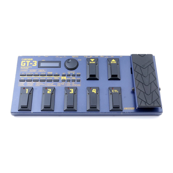
GT-3
Guitar Effects Processor
TABLE OF CONTENTS
Copyright © 1999 by ROLAND CORPORATION
All rights reserved. No part of this publication may be reproduced in any form without the written permission of ROLAND CORPORATION.
17059955
SERVICE NOTES
First Edition
Issued by RJA
............................................................................................... 1
............................................................................................... 2
............................................................................................... 3
............................................................................................... 6
............................................................................................... 6
............................................................................................... 8
............................................................................................... 9
............................................................................................... 15
............................................................................................... 16
............................................................................................... 17
............................................................................................... 18
............................................................................................... 19
............................................................................................... 20
............................................................................................... 21
............................................................................................... 22
Printed in Japan AA00 (DP)
SPECIFICATIONS
AD Conversion
24 bit AF Method 64 times Oversampling ∆ Σ Modulation
DA Conversion
20 bit 128 times Oversampling ∆ Σ Modulation
Sampling Frequency
44.1 kHz
Program Memories
340: 140 (User) + 200 (Preset)
Nominal Input Level
Page
INPUT:
-10 dBm
RETURN:
-10 dBm
Input Impedance
INPUT:
1 MΩ
RETURN:
220 kΩ
Nominal Output Level
OUTPUT:
0 dBm
SEND:
-10 dBm
Output Impedance
OUTPUT:
2 kΩ
SEND:
2 kΩ
Dynamic Range
100 dB or greater (IHF-A)
Controls
< Front >
Value dial
Effect select buttons
SFX, COMP/LM, WAH, OD/DS,
PREAMP/SP SIM, EQ, MOD, DELAY,
CHORUS, REVERB, MASTER,
PEDAL/ASSIGN
Exit button
Parameter buttons L/R
Write button
Manual button
Utility button
Tuner/Bypass button
Number pedals 1-4
Bank pedals up/down
Control pedal
Expression pedal
< Rear >
Output level knob
Power switch
Display
16 characters, 2 lines (backlit LCD)
Connectors
Input jack
Output jacks L(MONO)/R
Headphones jack (stereo mini type)
Send jack
Return jack
Sub expression pedal/Sub control pedal 1,2 jack
MIDI Connectors IN/OUT
Power Supply
AC 14 V; Supply AC adaptor
(BOSS BRC-120, 230, 240)
Current Draw
800 mA
Dimensions
487 (W) × 222 (D) × 97 (H) mm
19-3/16 (W) × 8-3/4 (D) × 3-7/8 (H) inches
Weight
4.0 kg/ 8 lbs 14 oz
Accessories
Owner's Manual
English
Japanese
Quick Start
English
Japanese
AC adaptor
BRC-120
BRC-230
BRC-240A (#00899101)
Euro Converter Plug (230VE only)
ECP01-5A
Options
Foot Switch:FS-5U, FS-5L
Expression Pedal:
EV-5 (Roland)
FV-300L+PCS-33 (Roland)
MIDI IMPLEMENTATION
English
Japanese
* 0 dBm = 0.775 Vrms
(#G6017276)
(#G6017277)
(#G6017279)
(#G6017278)
(#00899089)
(#00899090)
(#00905234)
(#17048954)
(#17048953)
Feb. 1999
1
Advertisement
Table of Contents

Related Manuals for Boss GT-3


Summary of Contents for Boss GT-3
-
Page 1: Table Of Contents
Return jack Sub expression pedal/Sub control pedal 1,2 jack MIDI Connectors IN/OUT Power Supply AC 14 V; Supply AC adaptor (BOSS BRC-120, 230, 240) Current Draw 800 mA Dimensions 487 (W) × 222 (D) × 97 (H) mm 19-3/16 (W) × 8-3/4 (D) × 3-7/8 (H) inches Weight 4.0 kg/ 8 lbs 14 oz... -
Page 2: Panel Layout
GT-3 Feb. 1999 Keytop Keytop PANEL LAYOUT D S-KEYTOP SD4H BLK D S-KEYTOP SX4H BLK (00900178) (00904256) FRONT VIEW Keytop Switch D S-KEYTOP MD3H BLK L-312LRD SKQKAB (22495279) (F5029117) (01780101) Knob LCD Cover Switch L-312LRD D R-KNOB L BLK DISPLAY COVER... -
Page 3: Exploded View
GT-3 Feb. 1999 EXPLODED VIEW [Part] PART CODE PART NAME DESCRIPTION Q'TY G2357108 FOOT G2817131 BOTTOM COVER 71235078 MAIN BOARD ASSY (EXG) 71235089 SW BOARD ASSY SW BD1+SW BD2+SW BD3+EXP BRD 1 x6 22495279 D S-KEYTOP MD3H BLK 249-279(W/WINDOW) 00904256... -
Page 4: Parts List
GT-3 Feb. 1999 15289109 M5216FP-600D IC (OP AMP) IC20 on Main Board PARTS LIST 15189261 M5218AFP-600E IC (OP AMP) TAPE IC16,IC19,IC21,IC22 on Main Board 15289156 M5222FP IC (VCA FLAT) IC17 on Main Board CONSIDERATIONS ON PARTS ORDERING SAFETY PRECAUTION: 15289106... - Page 5 GT-3 Feb. 1999 CRYSTAL, RESONATOR G2217708 PEDAL LABEL(4) for PEDAL SW ASSY G2217710 PEDAL LABEL(CTL) for PEDAL SW ASSY 00894023 MA-406 20MHZ TE24 CRYSTAL X1 on Main Board G2217709 PEDAL LABEL(DOWN) for PEDAL SW ASSY 01453167 SG-8002DC 67.7376MHZ CRYSTAL XT1 on Main Board...
-
Page 6: Identifying Version Number
Feb. 1999 IDENTIFYING VERSION NUMBER Transmitting / receiving data via MIDI The GT-3 can use exclusive messages to set another GT-3 to the 1. Turn the power off. same settings, or to transmit its settings to a device such as a 2. - Page 7 < Connections > units to match. When receiving data saved on a sequencer into the GT-3 Make connections as follows. Set the GT-3 to the device ID to which it was set when transmitting the data. MIDI OUT MIDI OUT...
-
Page 8: Factory Settings
Feb. 1999 Factory settings Restoring the factory settings (Initialization) To restore the factory settings of the GT-3, do as follows. You can < TUNER > initialize all settings, or only a specified section of the patch data in TUNER Pitch: A=440Hz the user area or utility settings. -
Page 9: Test Mode
GT-3 Feb. 1999 (2) Start from the "12.EXT OD CHECK" test. TEST MODE Pressing buttons [PRE AMP/SP SIM] and [EQ], turn the power on. CAUTION:The user data will be lost during the test mode. Save the user data on an external memory (e.g. sequencer, MC-50MK2) before entering test mode. - Page 10 GT-3 Feb. 1999 Normally, the buttons should be pressed in the order given 5. Battery below: (1) Effect selector buttons 5 . B a t t e r y From left to right and upper to lower. 0 0 0 0 3 .
- Page 11 GT-3 Feb. 1999 9. DS A/D/A[GAIN HIGH] 9 . D S A / D / A : H I G H [ G A I N H I G H ] Follow the steps described in the test 8. Note that the circuit gain is set to high during this test.
- Page 12 GT-3 Feb. 1999 OUTPUT level control:MAX EXT OD CHECK Oscilloscope:0.5V/DIV,0.5mS/DIV 1 2 . E X T C H E C K [ D S P → E X T → O U T ] Check the signal path: A) Connect the oscilloscope to either OUTPUT socket and verify rectangular output waveform.
- Page 13 GT-3 Feb. 1999 14.DSP pitch interrupt signal I n s e r t a b l a n k 1 4 . D S P I N T 0 ( 6 7 p ) p l u g i n t o t h e RETURN socket.
- Page 14 GT-3 Feb. 1999 INPUT 18.Calibrate EXP 1 8 . C a l i b r a t e E X P SEND This step set the margin at the lowest level and the margin at the highest level. RETURN 1) Set the pedal at fully released (up) position. Keep your hand away from the pedal.
-
Page 15: Block Diagram
GT-3 Feb. 1999 BLOCK DIAGRAM/ MIDI OUT IN EXP BOARD ASSY PEDAL VR SUB EXP PEDAL SUB CTL 1,2 SW 1 BOARD ASSY IC18b IC15b PANEL SW,LED INPUT ENCODER IC15a IC1 CPU PHONES SW 2 BOARD ASSY IC14 H8/3006 PEDAL SW,LED... -
Page 16: Circuit Diagram (Sw Board)
GT-3 Feb. 1999 CIRCUIT DIAGRAM (SW BOARD) PEDAL 1 PEDAL 2 PEDAL 3 PEDAL 4 PEDAL CTL 6216 014 110 808 SW BOARD3 ASSY 71235089 READ1 SKQKAH 1SS133 SKQKAH 1SS133 SKQKAH 1SS133 SKQKAH 1SS133 SKQKAH 1SS133 BANK DOWN BANK UP... -
Page 17: Circuit Diagram (1/2) (Main)
GT-3 Feb. 1999 CIRCUIT DIAGRAM (1/2) (MAIN) GAIN_SW MIDI OD_SW DS_SW IC24C IC24D YKF51-5054 74HC04 74HC04 DS SW OD SW GAIN SW IC24G GAIN CV IC22C 74HC04 MUTE M5218AFP 1SS352 C273 IC24E IC24F C272 74HC04 74HC04 10/16 IC22A 47/16 2.2k... -
Page 18: Circuit Diagram (2/2) (Main)
GT-3 Feb. 1999 CIRCUIT DIAGRAM (2/2) (MAIN) IC19C R202 M5218AFP IC20C 47/2W 2SC4213A M5216AFP IC14 C113 R105 VCOM PHONE C107 C259 C229 C224 470/16 100/16 100/16 C114 R130 HSJ0857-01-1210 C119 AGND R129 C109 C260 0.01 1.2k 470/16 C112 R203 C106... -
Page 19: Circuit Board (Main)
GT-3 Feb. 1999 CIRCUIT BOARD (MAIN) For Nordic Countries Apparatus containing Lithium batteries ADVARSEL! Lithiumbatteri - Eksplosionsfare ved fejlagtig håndtering. Udskiftning må kun ske med batteri af samme fabrikat og type. Levér det brugte batteri tilbage til leverandøren. ADVARSEL! Lithiumbatteri - Eksplosjonsfare. -
Page 20: Circuit Board (Sw Board)
GT-3 Feb. 1999 CIRCUIT BOARD (SW BOARD) /... -
Page 21: Error Message
GT-3 Feb. 1999 If the battery voltage for memory back-up is "2.7V" or less, the ERROR MESSAGE display shows "Low". DSP Check 4 . B a t t e r y B a t t e r y P R A M : N G I R A M : - - If no battery connected, the display shows "No Battery !!". -
Page 22: Change Information
GT-3 Feb. 1999 DSP pitch interrupt signal check CHANGE INFORMATION Rom Version UP 1 6 . D S P I N T 0 ( 6 7 p ) 0 0 0 - - - E R R O R ! - - - Effective Symptom:Interrupt signal generated at DSP(IC8) is not recognized.
Need help?
Do you have a question about the GT-3 and is the answer not in the manual?
Questions and answers