Table of Contents
Advertisement
Quick Links
Advertisement
Table of Contents

Related Manuals for Smartgen HGM9600 Series


Summary of Contents for Smartgen HGM9600 Series
- Page 1 HGM9600 SERIES (HGM9610/HGM9620) GENSET CONTROLLER USER MANUAL...
-
Page 2: Table Of Contents
14.2 GSM SHORT MESSAGE REMOTE CONTROL ................. 58 14.3 CONTROLLER AND GSM MODULE CONNECTION ................ 59 15 CONNECTIONS OF CONTROLLER WITH J1939 ENGINE ..............60 15.1 CUMMINS ISB/ISBE ........................60 15.2 CUMMINS QSL9 ..........................60 HGM9600 Series Genset Controller User Manual Page 2 of 73... - Page 3 16.2 NETWORK CLIENT MODE ....................... 69 16.3 WEB SERVER MODE ........................69 16.4 NETWORK CABLE CONNECTION ....................70 17 MICRO SD ............................... 72 18 USB ................................72 19 FAULT FINDING ............................73 HGM9600 Series Genset Controller User Manual Page 3 of 73...
- Page 4 All rights reserved. No part of this publication may be reproduced in any material form (including photocopying or storing in any medium by electronic means or other) without the written permission of the copyright holder. Smartgen reserves the right to change the contents of this document without prior notice. Table 1 Software Version Date...
- Page 5 This manual is suitable for HGM9600 series controller only. (HGM9610/HGM9620) Clarification of notation used within this publication. Table 2 Sign Instruction Sign Instruction Highlights an essential element of a procedure to ensure correctness. NOTE Indicates a procedure or practice, which, if not strictly observed, could result in CAUTION! damage or destruction of equipment.
-
Page 6: Overview
1 OVERVIEW HGM9600 series genset controllers are used for genset automation and monitor control system of single unit to achieve automatic start/stop, data measure, alarm protection and “three remote” (remote control, remote measuring and remote communication). The controller adopts large liquid crystal display (LCD) and selectable Chinese, English or other languages interface with easy and reliable operation. -
Page 7: Models Comparison
(2) HGM96XX’s analog sensors are composed by 3 fixed sensors (temperature, pressure, liquid level) and 2 configurable sensors. NOTE: Functions of mentioned herein HGM9210/HGM9220/HGM9310/HGM9320/HGM9410/HGM9420 /HGM9510/HGM9520 controllers can be changed, please check the corresponding user manual for accurate information. HGM9600 Series Genset Controller User Manual Page 7 of 73... -
Page 8: Performance And Characteristics
Frequency Hz Frequency Hz Load Current IA, IB, IC Each phase and total active power kW Each phase and total reactive power kvar Each phase and total apparent power KVA HGM9600 Series Genset Controller User Manual Page 8 of 73... - Page 9 ♦ Can control engine heater, cooler and fuel pump; ♦ With maintenance function. Actions (warning, shutdown or trip and stop) can be set when HGM9600 Series Genset Controller User Manual Page 9 of 73...
- Page 10 ♦ Metal fixing clips enable perfect performance in high temperature environment; ♦ Modular design, anti-flaming ABS enclosure, pluggable connection terminals and embedded installation way; compact structure with easy mounting. HGM9600 Series Genset Controller User Manual Page 10 of 73...
-
Page 11: Specification
(-25~+70)°C Protection Level IP55 Gasket Apply AC2.2kV voltage between high voltage terminal and low Insulating Intensity voltage terminal; The leakage current is not more than 3mA within 1min. Weight 0.95kg HGM9600 Series Genset Controller User Manual Page 11 of 73... -
Page 12: Operation
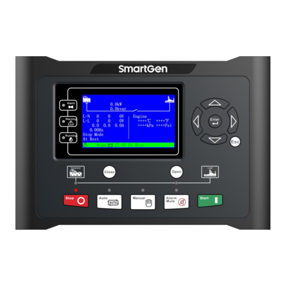
5 OPERATION INDICATOR LIGHT Fig.1 HGM9610 Front Panel Fig.2 HGM9620 Front Panel HGM9600 Series Genset Controller User Manual Page 12 of 73... - Page 13 Mains normal indicator: It is light on when mains is normal; flashing when mains state is abnormal; off when there is no mains power. HGM9600 Series Genset Controller User Manual Page 13 of 73...
-
Page 14: Key Functions
NOTE: In manual mode, pressing simultaneously will force generator to crank. Successful start will not be judged according to crank disconnect conditions, operator will have to crank the starter motor manually; HGM9600 Series Genset Controller User Manual Page 14 of 73... -
Page 15: Lcd Display
CAUTION: Default password is 00318, user can change it in case of others change the advanced parameters setting. Please clearly remember the password after changing. If you forget it, please contact SmartGen services and send all information in the controller page of “ABOUT” to us. -
Page 16: User Menu And Parameters Setting
USER MENU AND PARAMETERS SETTING Press and hold for more than 3 seconds to enter user menu; ★Parameter After entering the correct password (factory default password is 00318) you can enter parameter HGM9600 Series Genset Controller User Manual Page 16 of 73... - Page 17 > Warming Up Time Temp. Sensor > Cooling Time OP Sensor > Stop Idle Time Level Sensor > ETS Hold Time Config. Sensor 1 > Wait Stop Time Config. Sensor 2 HGM9600 Series Genset Controller User Manual Page 17 of 73...
- Page 18 > Crank Rest Time > Safety On Time > Start Idle Time > Warming Up Time > Cooling Time > Stop Idle Time > ETS Hold Time > Wait Stop Time HGM9600 Series Genset Controller User Manual Page 18 of 73...
-
Page 19: Auto Start/Stop Operation
When start delay is over, preheat relay outputs (if this be configured), “preheat start delay XX s” is shown at the bottom line of LCD. When preheat delay is over, fuel relay outputs 1s and then start relay output; if engine crank fails HGM9600 Series Genset Controller User Manual Page 19 of 73... - Page 20 Stop” alarm. (If gen-set stopped successfully after warning of “Fail to Stop”, it will enter “after stop time” and remove alarm) Enter “generator at rest” as soon as “after stop time” is over. HGM9600 Series Genset Controller User Manual Page 20 of 73...
-
Page 21: Manual Start/Stop Operation
Detecting transfer failure while generator switch on. When detecting time out, if switch on failed, it needs to wait for generator to switch on. If transfer failed and warning HGM9600 Series Genset Controller User Manual Page 21 of 73... -
Page 22: Hgm9610 Switch Control Procedures
Generator unload is transferred into generator load, after the delay of switch on, detecting transfer failure while switch on outputting. When detecting time out, if switch on failed, to wait for switch on. HGM9600 Series Genset Controller User Manual Page 22 of 73... - Page 23 When using ATS of having interposition, switch off “SELECT Disable” or “SELECT Enable” both are OK. If choose “SELECT Enable”, switch off output should be configured; When using AC contactor, switch off “SELECT Enable” is recommended. HGM9600 Series Genset Controller User Manual Page 23 of 73...
-
Page 24: Protection
Gen Phase Sequence When controller detects the reverse phase, it will send warn signal. Wrong Switch Fail Warn When controller detects the switch on and off fail, and the action HGM9600 Series Genset Controller User Manual Page 24 of 73... - Page 25 When controller detects earth current is greater than value of setting, Earth Fault and the action “Warning” alarm is set, it will send a “warning” alarm signal. HGM9600 Series Genset Controller User Manual Page 25 of 73...
-
Page 26: Shutdown Alarm
When controller detects temperature is higher than the set value, it High Temp. will send a stop signal. Oil Pressure Sensor When controller detects sensor is open circuit, and the action select Open “shutdown”, it will send a stop signal. HGM9600 Series Genset Controller User Manual Page 26 of 73... - Page 27 Digital Input Port will send a shutdown signal. When controller detects the earth current is higher than the set value, Earth Fault and the action select “shutdown”, it will send stop signal. HGM9600 Series Genset Controller User Manual Page 27 of 73...
-
Page 28: Trip And Stop Alarm
Digital Input a trip signal. When controller detects the earth current is higher than the set value, and Earth Fault the action select “trip”, it will send a trip signal. HGM9600 Series Genset Controller User Manual Page 28 of 73... -
Page 29: Wirings Connection
7 WIRINGS CONNECTION HGM9600 series controller’s rear as following: Fig.3 HGM9600 Rear Panel Table 12 Description of Terminal Connection Function Cable Size Remarks 2.5mm Connected with negative of starter battery Connected with positive of starter battery. If wire length 2.5mm is over 30m, better to double wires in parallel. - Page 30 (rated 5A) Outside connected to secondary coil of current 1.5mm transformer (rated 5A) Outside connected to secondary coil of current 1.5mm transformer (rated 5A) CT COM 1.5mm See following installation instruction HGM9600 Series Genset Controller User Manual Page 30 of 73...
- Page 31 NOTE: Ethernet ports in controller rear panel are website port, user can directly configure and monitor controller via NOTE: Please refer to the Module Comparison in this manual for more details. HGM9600 Series Genset Controller User Manual Page 31 of 73...
-
Page 32: Scopes And Definitions Of Programmable Parameters
Time of pre-powering heat plug before Preheat Delay (0~3600)s starter is powered up. Cranking Time (3~60)s Time of starter power up. Crank Rest Time (3~60)s The waiting time before second power up HGM9600 Series Genset Controller User Manual Page 32 of 73... - Page 33 (default: 2s) also can be Shutdown set. Setting value is percentage of rated speed Under Speed (0~200)% and delay value (default: 3s) also can be Shutdown set. HGM9600 Series Genset Controller User Manual Page 33 of 73...
- Page 34 See the installation instruction. Generator Setting 0: 3P4W; 1: 3P3W; AC System (0~3) 2: 2P3W; 3: 1P2W. Numbers of generator pole, used for Poles (2~32) calculating starter rotate speed when HGM9600 Series Genset Controller User Manual Page 34 of 73...
- Page 35 Setting value is percentage of generator Under Freq. Warn (0~200)% rated freq. Delay value (default: 5s) and return value (default: 86%) also can be set. Loss of Phase (0~1) 0: Disable 1: Enable HGM9600 Series Genset Controller User Manual Page 35 of 73...
- Page 36 1: Enable All the settings about Ethernet (IP address, Ethernet (0-1) subnet mask) will active after the next time power on. SD Card (0-1) 0: Disable 1: Enable GSM Setting HGM9600 Series Genset Controller User Manual Page 36 of 73...
- Page 37 The delay value (default: 5s) and return value (default: 138) also can be set. Liquid Level Sensor Curve Type (0~15) SGH. See Table 16. Open Circuit (0~2) 0: Warn; 1: Shutdown; 2: No action Action HGM9600 Series Genset Controller User Manual Page 37 of 73...
- Page 38 Contents Setting (0~50) User defined. See Table 15. 0: Closed to active Active Type (0~1) 1: Open to active 0: From safety on 1: From starting Arming (0~3) Always 3: Never HGM9600 Series Genset Controller User Manual Page 38 of 73...
- Page 39 (0~1) 1: Normally close Aux. Output Port 2 Contents Setting (0~239) Idle control output. See Table 14. 0: Normally open; Active Type (0~1) 1: Normally close Aux. Output Port 3 HGM9600 Series Genset Controller User Manual Page 39 of 73...
- Page 40 T: Overcurrent delay (second) t: Timing multiplier ratio IA: Current max. load current (L1/L2/L3) IT: Overcurrent setting value Example: t = 36 IA = 550A IT =500A Conclusion: T = 3600s (1hour) HGM9600 Series Genset Controller User Manual Page 40 of 73...
-
Page 41: Enable Definition Of Auxiliary Output Ports
Actions in period of pre-heating to safety run. Remote PC Output This port is controlled by communication (PC). Power for GSM module (GSM module is reset when GSM GSM Power communication failed). HGM9600 Series Genset Controller User Manual Page 41 of 73... - Page 42 Action when charge failure warning alarms. Reserved Reserved Reserved ECU Warn Indicate ECU sends a warning signal. ECU Shutdown Indicate ECU sends a shutdown signal. ECU Comm. Fail Indicate controller not communicates with ECU. HGM9600 Series Genset Controller User Manual Page 42 of 73...
- Page 43 Over Power Action when controller detects generator have over power. Reserved Reverse Power Action when controller detects generator have reverse power. Over Current Action when over current. Reserved Mains Blackout HGM9600 Series Genset Controller User Manual Page 43 of 73...
- Page 44 Reserved Stop Mode Action in stop mode. Manual Mode Action in Manual mode. Reserved Auto Mode Action in Auto mode. Generator On Load Mains On Load Reserved Reserved Reserved Reserved HGM9600 Series Genset Controller User Manual Page 44 of 73...
-
Page 45: Custom Period Output
Close when probably condition output S2 is active /inactive: close when active (disconnect when inactive); Contents of probably condition output S3: input port 3 is active; Close when probably condition output S3 is active /inactive: close when active (disconnect when inactive); HGM9600 Series Genset Controller User Manual Page 45 of 73... -
Page 46: Defined Contents Of Auxiliary Input Ports (All Gnd (B-) Active)
Connect mains loading switch’s Aux. Point. Inhibit Mains Load Prohibit mains switch on when input is active. Auto Mode Lock When input is active, controller enters into Auto mode; all the HGM9600 Series Genset Controller User Manual Page 46 of 73... - Page 47 This is simulate G-close key when HGM9610 controller is Simulate G-Load key applied. This is simulate M-open key when HGM9610 controller is Simulate M-Load key applied. Reserved Reserved Reserved Reserved HGM9600 Series Genset Controller User Manual Page 47 of 73...
- Page 48 In Auto mode, mains are abnormal when input is active. Alternative Config1 Users can set different parameters to make it easy to select Alternative Config2 current configuration via input port. Alternative Config3 Reserved HGM9600 Series Genset Controller User Manual Page 48 of 73...
-
Page 49: Selection Of Sensors
0~6KΩ, default 3 SGD is SGH sensor. 4 SGH 5~15 Reserved NOTE: User should make special declare when order controller if your genset equip with sensor of 4~20mA. HGM9600 Series Genset Controller User Manual Page 49 of 73... -
Page 50: Conditions Of Crank Disconnect Selection
(can be used in water pump set); if not select speed sensor in crank disconnect setting, the rotating speed displayed in controller is calculated by generator frequency and number of poles. HGM9600 Series Genset Controller User Manual Page 50 of 73... -
Page 51: Parameters Setting
NOTE: Configurable input could not be set as same items; otherwise, there are abnormal functions. However, the configurable output can be set as same items. HGM9600 Series Genset Controller User Manual Page 51 of 73... -
Page 52: Sensors Setting
Fig.4 Sensor Curve Table 18 Normal Pressure Unit Conversion kgf/cm - - - 1.02x10 1x10 1.45x10 1kgf/cm 9.8x10 0.98 14.2 1bar 1x10 1.02 14.5 1psi 6.89x10 7.03x10 - 6.89x10 - HGM9600 Series Genset Controller User Manual Page 52 of 73... -
Page 53: Commissioning
ATS as generator load. If not like this, please check ATS’ wires connection of control part according to this manual. If there is any other question, please contact SmartGen’s service. HGM9600 Series Genset Controller User Manual... -
Page 54: Typical Application
Fig.5 HGM9610 Typical Application Diagram Fig.6 HGM9620 Typical Application Diagram NOTE: Fuse F1: min. 2A; max. 20A. Fuse F2: max. 32A. Users should select suitable fuse depend on practical application. HGM9600 Series Genset Controller User Manual Page 54 of 73... - Page 55 Fig.7 3 Phase 3 Wire Application Diagram Fig.8 2 Phase 3 Wire Application Diagram Fig.9 Single Phase 2 Wire Application Diagram HGM9600 Series Genset Controller User Manual Page 55 of 73...
-
Page 56: Installation
Battery Voltage Input NOTE: HGM9600 series controller can suit for widely range of battery voltage DC(8~35)V. Negative of battery must be connected with the engine shell. The diameter of wire which from power supply to battery must be over 2.5mm . - Page 57 CAUTION! When controller had been installed in control panel, if need the high voltage test, please disconnect controller’s all terminal connections, in order to prevent high voltage into controller and damage it. HGM9600 Series Genset Controller User Manual Page 57 of 73...
-
Page 58: Gsm Short Message Alarm And Remote Control
Gets details information of genset. be set via PC software. NOTE: When sending orders, users need to follow SMS orders in above form and all the letters must be capital. HGM9600 Series Genset Controller User Manual Page 58 of 73... -
Page 59: Controller And Gsm Module Connection
NOTE: Its national and area’s cods must be added. e.g. China: 8613666666666. 14.3 CONTROLLER AND GSM MODULE CONNECTION The diagram below illustrates the application of SmartGen GSM-3 module (international version). Fig.11 Controller and GSM Module Connection HGM9600 Series Genset Controller User Manual... -
Page 60: Connections Of Controller With J1939 Engine
CAN GND SAE J1939 shield-E (connect with ECU terminal only). CAN(H) SAE J1939 signal-C Using impedance 120Ω connecting line. CAN(L) SAE J1939 return-D Using impedance 120Ω connecting line. Engine type: Cummins-CM850. HGM9600 Series Genset Controller User Manual Page 60 of 73... -
Page 61: Cummins Qsm11(Import)
SAE J1939 shield-E (connect with ECU terminal only). CAN(H) SAE J1939 signal-C Using impedance 120Ω connecting line. CAN(L) SAE J1939 return-D Using impedance 120Ω connecting line. Engine type: Cummins QSX15-CM570. HGM9600 Series Genset Controller User Manual Page 61 of 73... -
Page 62: Cummins Gcs-Modbus
Connect with starter coil directly. communication shielding line CAN GND (connect with controller’s this terminal only). CAN(H) Using impedance 120Ω connecting line. CAN(L) Using impedance 120Ω connecting line. Engine type: Common J1939. HGM9600 Series Genset Controller User Manual Page 62 of 73... -
Page 63: Cummins Qsz13
Connect to starter coil directly. communication shielding line CAN GND (connect with controller’s terminal only). CAN(H) CAN(H) Using impedance 120Ω connecting line. CAN(L) CAN(L) Using impedance 120Ω connecting line. Engine type: Common J1939. HGM9600 Series Genset Controller User Manual Page 63 of 73... -
Page 64: Deutz Emr2
Fuel relay output Start relay output communication shielding line CAN GND (connect with one terminal only). CAN(H) Using impedance 120Ω connecting line. CAN(L) Using impedance 120Ω connecting line. Engine type: MTU-MDEC-303. HGM9600 Series Genset Controller User Manual Page 64 of 73... -
Page 65: Mtu Adec (Smart Module)
CAN GND X23 3 (connect with controller’s this terminal only). CAN(H) X23 2 Using impedance 120Ω connecting line. CAN(L) X23 1 Using impedance 120Ω connecting line. Engine type: Common J1939. HGM9600 Series Genset Controller User Manual Page 65 of 73... -
Page 66: Perkins
Table 42 “Stand alone” Connector Terminals of controller “Stand alone” connector Remark Fuel relay output Start relay output ECU power; Auxiliary output 1 Set Auxiliary output 1 as “ECU power”. HGM9600 Series Genset Controller User Manual Page 66 of 73... -
Page 67: Volvo Edc4
Set Auxiliary output 2 as “ECU power”. Negative power Positive power communication shielding line CAN GND (connect with controller’s terminal only). CAN(H) 1(Hi) Using impedance 120Ω connecting line. CAN(L) 2(Lo) Using impedance 120Ω connecting line. HGM9600 Series Genset Controller User Manual Page 67 of 73... -
Page 68: Yuchai
CAN(L) 1.34 Using impedance 120Ω connecting line. Engine type: GTSC1. NOTE: If there is any question of connection between controller and ECU communication, please feel free to contact SmartGen’s service. HGM9600 Series Genset Controller User Manual Page 68 of 73... -
Page 69: Ethernet Port
The communication between the controller and monitoring equipment is carried out using TCP ModBus protocol. NOTE: In this connection mode controller parameters can be set. SmartGen provides testing software for this connection mode. Communication protocol can be obtained from the SmartGen service. -
Page 70: Network Cable Connection
Table 49 Controller Network Port Description Name Description Tranceive Data+ Tranceive Data- Receive Data+ Not connected Not connected Receive Data- Not connected Not connected 2. Controller and PC are connected directly using a network cable: HGM9600 Series Genset Controller User Manual Page 70 of 73... - Page 71 Parallel cable: EIA/TIA 568A standard on both ends or EIA/TIA 568B standard on both ends. NOTE: If switchboard (or router) network port has Auto MDI/MDIX function, crossover cable can also be used. HGM9600 Series Genset Controller User Manual Page 71 of 73...
-
Page 72: Micro Sd
17 MICRO SD HGM9600 series controller supports Micro SD card, the controller can regularly save gen-set operation data (engine speed, temperature, oil pressure, generator voltage, generator frequency, load current, load power, alarm information etc.) to Micro SD card. For user convenience, the controller creates a date named file (e.g. -
Page 73: Fault Finding
Get information from LCD of alarm page; ECU warning or stop If there is detailed alarm, check engine according to description. If not, please refer to engine manual according to SPN alarm code. _________________________________ HGM9600 Series Genset Controller User Manual Page 73 of 73...
Need help?
Do you have a question about the HGM9600 Series and is the answer not in the manual?
Questions and answers