Table of Contents
Advertisement
Advertisement
Table of Contents

Subscribe to Our Youtube Channel
Related Manuals for Smartgen HGM501


Summary of Contents for Smartgen HGM501
- Page 1 HGM501 Gen-set Controller USER MANUAL Smartgen Technology...
- Page 2 All rights reserved. No part of this publication may be reproduced in any material form (including photocopying or storing in any medium by electronic means or other) without the written permission of the copyright holder. Smartgen Technology reserves the right to change the contents of this document without prior notice. Version History...
-
Page 3: Table Of Contents
7. CONFIGURABLE PARAMETERS ..............10 7.1. CONFIGURABLE PARAMETERS TABLE ............... 10 7.2. PARAMETER CONFIGURATION ................11 8. COMMISSIONING ................... 13 9. TYPICAL WIRING DIAGRAM ................14 10. INSTALLATION ....................14 11. TROUBLESHOOTING ..................15 HGM501 Genset Controller Version V1.0 2012-07-10 Page 3 of 15... -
Page 4: Overview
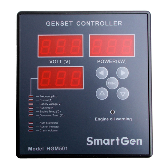
HGM501 gen-set controller contains the microprocessor allows precise measurement of multiple parameters, which can be configured using controller front panel. With simple wiring, compact structure and high reliability, HGM501 can be widely used for data display and fault protection of a large number of diesel and petrol generator sets. -
Page 5: Technical Data
Operating conditions Temperature: (-25~+70)° C Humidity: (20~90)% Storage conditions Temperature: (-30~+80)° C Protection level IP42 Object: input/output/power supply Insulation strength Quoted standard: IEC688-1992 Test method: AC1.5kV/1min Leakage current 3mA Weight 0.216kg HGM501 Genset Controller Version V1.0 2012-07-10 Page 5 of 15... -
Page 6: Operation
LEFT 2. During normal operation press this button to switch to the next (upper) LED. 1. During parameter configuration press this button RIGHT to enter the next menu. HGM501 Genset Controller Version V1.0 2012-07-10 Page 6 of 15... -
Page 7: Start/Stop Operation
During normal running of the gen-set, if low oil pressure signal is detected, the set will be stopped. Manual stop Under any circumstances, if starter key is turned from ON to OFF position, it will lead to shutdown. HGM501 Genset Controller Version V1.0 2012-07-10 Page 7 of 15... -
Page 8: Auto Protection
Battery voltage protection Battery voltage protection is enabled irrespective of whether auto protection mode is enabled or not and whether gen-set is running. If battery voltage value is HGM501 Genset Controller Version V1.0 2012-07-10 Page 8 of 15... -
Page 9: Terminal
NOTE: During Safety On delay, protection is disabled; after Safety On Delay, when voltage, frequency, overload, high temperature protection is initiated, fuel output deactivates. 6. TERMINAL HGM501 controller back panel is shown below: Terminal connections description Terminal Function Wire size... -
Page 10: Configurable Parameters
Parameter Range factory Description value 1P:1P2W AC system 2P:2P3W 3P:3P4W 110 V 115 V 120 V Rated Generator rated voltage 130 V voltage value selection 220 V 230 V 240V HGM501 Genset Controller Version V1.0 2012-07-10 Page 10 of 15... -
Page 11: Parameter Configuration
AC wire type and to confirm and automatically enter the next menu item; Rated voltage value settings: there are 7 possible variants of voltage (110/115/120/130/220/230/240V), use to switchover between HGM501 Genset Controller Version V1.0 2012-07-10 Page 11 of 15... - Page 12 Generator temperature sensor type setting: the same as 7. Turn the start key from ON to OFF position to finish configuration. NOTE: during configuration use button to enter the next menu item and HGM501 Genset Controller Version V1.0 2012-07-10 Page 12 of 15...
-
Page 13: Commissioning
5. Then change start key position to START to start cranking. After the engine is fired, remove start key; voltage, frequency and power windows will show true collected values. 6. For further information please contact Smartgen services. HGM501 Genset Controller Version V1.0... -
Page 14: Typical Wiring Diagram
Overall and cutout dimensions can be seen below (unit: mm) Battery Voltage Input NOTE: HGM501 controller is suitable for 9-18 VDC battery voltage. Battery negative must be reliably connected to the enclosure of the engine. The controller power supply B+ and B- must be connected to battery positive and HGM501 Genset Controller Version V1.0... -
Page 15: Troubleshooting
Check fuel return circuit and wiring Fail to start Check start battery Consult engine manual Starter motor does Check the wiring to the starter respond Check start battery HGM501 Genset Controller Version V1.0 2012-07-10 Page 15 of 15...
Need help?
Do you have a question about the HGM501 and is the answer not in the manual?
Questions and answers