
Subscribe to Our Youtube Channel
Related Manuals for Smartgen HGM9420N


Summary of Contents for Smartgen HGM9420N
- Page 1 HGM9420N_HGM9420LT GENSET CONTROLLER USER MANUAL SMARTGEN (ZHENGZHOU) TECHNOLOGY CO.,LTD.
- Page 2 SmartGen Technology at the address above. Any reference to trademarked product names used within this publication is owned by their respective companies. SmartGen Technology reserves the right to change the contents of this document without prior notice. Table 1 Software Version Date...
- Page 3 HGM9420N_HGM9420LT GENSET CONTROLLER USER MANUAL Table 2 Symbol Instruction Symbol Instruction Highlights an essential element of a procedure to ensure correctness. NOTE Indicates a procedure or practice, which, if not strictly observed, could result in CAUTION damage or destruction of equipment. Indicates a procedure or practice, which could result in injury to personnel or loss of life WARNING if not followed correctly.
-
Page 4: Table Of Contents
HGM9420N_HGM9420LT GENSET CONTROLLER USER MANUAL CONTENTS OVERVIEW ............................6 PERFORMANCE AND CHARACTERISTICS ..................7 SPECIFICATION ..........................10 OPERATION ............................. 12 INDICATOR LAMP ........................12 PUSHBUTTONS ........................13 LCD DISPLAY ......................... 14 4.3.1 MAIN DISPLAY ........................14 4.3.2 USER MENU AND PARAMETER SETTING ..............16 AUTO START/STOP OPERATION .................. - Page 5 HGM9420N_HGM9420LT GENSET CONTROLLER USER MANUAL 12 COMMISSIONING ..........................93 13 TYPICAL APPLICATION ........................94 14 NEL TRIP DESCRIPTION ........................ 96 15 DUMMY LOAD CONNECTION ......................97 16 OIL CONSUMPTION ILLUSTRATION ..................... 98 17 ETHERNET PORT ..........................98 18 HOST USB PORT ..........................99 19 INSTALLATION ..........................
-
Page 6: Overview
HGM9420N_HGM9420LT GENSET CONTROLLER USER MANUAL OVERVIEW HGM9420N_HGM9420LT genset controller is used for automatic control of single genset to realize automatic start/AMF/synchronous transfer/cloud monitoring. This series of controller integrates digitalization, intelligence, and network technology. It fits with LCD graphic display, optional Chinese, English and other languages interface, and it is reliable and easy to use. -
Page 7: Performance And Characteristics
HGM9420N_HGM9420LT GENSET CONTROLLER USER MANUAL PERFORMANCE AND CHARACTERISTICS HGM9420N_HGM9420LT: fits Mains-Gen power monitoring for Mains/Gen automatic transfer control (AMF). It is used for single unit automation system formed by one Mains and one Genset. Mains can be disabled by disabling mains parameters for single unit automation. By remote start signal genset auto start and stop can be controlled. - Page 8 HGM9420N_HGM9420LT GENSET CONTROLLER USER MANUAL Load output percentage (active power/rated power)x100% Average load of current run Total energy of current run Average load of last time Historical max average load — Mains has over voltage, under voltage, over frequency, under frequency, loss of phase, reverse phase sequence function;...
- Page 9 HGM9420N_HGM9420LT GENSET CONTROLLER USER MANUAL — A USB Host port, where U flash of FAT32 format can be inserted, can put controller configured parameters to the controller, or save controller parameters to the U flash; Historical data can be saved; —...
-
Page 10: Specification
HGM9420N_HGM9420LT GENSET CONTROLLER USER MANUAL SPECIFICATION Table 3 Technical Specification Parameter Details Working Voltage Range: DC8V - DC35V continuous, DC reverse connection protection Resolution: 0.1V Accuracy: 1% <7W (Standby mode: ≤2.5W) Overall Consumption Phase voltage Range: AC15V - AC360V (ph-N) Resolution: 0.1V Accuracy: 0.5% AC Voltage... - Page 11 Under the temperature of -40° C, after power on for 20s it can display LCD Display (HGM9420LT) normally; after power on for 2min, dynamic display responses normally; Storage Conditions HGM9420N: Temperature:(-30~+80)° C HGM9420LT: Temperature:(-45~+80)° C Front Enclosure: IP65 when rubber-ring gasket is installed between Protection Level the enclosure and the control screen...
-
Page 12: Operation
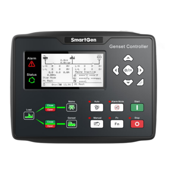
HGM9420N_HGM9420LT GENSET CONTROLLER USER MANUAL Parameter Details Apply AC2.2kV voltage between high voltage terminal and low voltage Insulation Intensity terminal and the leakage current is not more than 3mA within 1min. Weight 0.91kg OPERATION 4.1 INDICATOR LAMP Fig.1 HGM9420N_HGM9420LT Indication NOTE: Description for parts of indicators: Table 4 Alarm indicator Description Alarm Type... -
Page 13: Pushbuttons
HGM9420N_HGM9420LT GENSET CONTROLLER USER MANUAL NOTE 5: When mains is disabled, mains normal indicator is extinguished, meanwhile mains close/open keys won't work. 4.2 PUSHBUTTONS Table 5 Button Function Description Icons Buttons Description Stop the running generator in Auto/Manual mode; Reset alarm in stop mode; Stop Key Press for over 3s, panel indicators can be tested (lamp test);... -
Page 14: Lcd Display
CAUTION: Factory default password is ―00318‖, and users can change it in case others change the advanced parameter settings. Please clearly remember the password after changing. If you forget it, please contact SmartGen services and send the PD information in the controller page of ―ABOUT‖ to the service personnel. - Page 15 Module date and time, input and output status, communication indication, RS485 configuration, Ethernet configuration (if enabled), LCD temperature, MCU temperature. NOTE: HGM9420N controller LCD temperature is +++℃. About page includes the following contents: Release software version, hardware version, and product PD number.
-
Page 16: User Menu And Parameter Setting
HGM9420N_HGM9420LT GENSET CONTROLLER USER MANUAL 4.3.2 USER MENU AND PARAMETER SETTING Press key for more than 1s and it enters user menu. Parameter Setting After inputting the correct password (factory default password is 00318) you can enter the parameter setting screen. - Page 17 HGM9420N_HGM9420LT GENSET CONTROLLER USER MANUAL Switch Start Idle Time Sensor Warming Up Time Digital Input Cooling Time Start Delay Table 2: Stop Delay 00030s is used to change the contents needed to Pre-heat Delay Fuel Delay set; is used to confirm the setting (Table 3), Cranking Time Crank Rest Time returns to previous menu (Table 1);...
-
Page 18: Auto Start/Stop Operation
HGM9420N_HGM9420LT GENSET CONTROLLER USER MANUAL 4.4 AUTO START/STOP OPERATION 4.4.1 ILLUSTRATION Press button and the indicator beside is illuminated, which means the genset is at Auto Start Mode. 4.4.2 AUTOMATIC START SEQUENCE HGM9420N_HGM9420LT start conditions: Mains enabled: when mains is abnormal (over voltage, under voltage, over frequency, under frequency, loss of phase, reverse phase sequence), controller enters "Mains Abnormal Delay", LCD mains status line displays countdown. -
Page 19: Automatic Stop Sequence
HGM9420N_HGM9420LT GENSET CONTROLLER USER MANUAL procedure h) or i), generator close relay is deactivated, and moreover, genset is off load. 4.4.3 AUTOMATIC STOP SEQUENCE In the process of genset normal running, if Mains recovers, genset enters "Mains Voltage Normal Delay". When Mains normal is confirmed, Mains status indicator is illuminated and "Stop Delay" is initiated. -
Page 20: Controller Switch Control Procedures
HGM9420N_HGM9420LT GENSET CONTROLLER USER MANUAL CONTROLLER SWITCH CONTROL PROCEDURES 5.1 SWITCH CONTROL PROCEDURE FOR SYNC TRANSFER DISABLED 5.1.1 MANUAL TRANSFER PROCESS When controller is in Manual mode, the switch control procedures will start through manual transfer procedures. Users can control the loading transfer of ATS via pressing switch close/open keys. Mains Enabled:If open detection is disabled, press gen close/open key ;... -
Page 21: Switch Control Procedure For Synchronous Transfer Enabled
HGM9420N_HGM9420LT GENSET CONTROLLER USER MANUAL generator on-load, after close delay, in the process of close output, transfer failure is detected. When the detection time is due, if close fails, then close is waited for, otherwise close is completed. • If transfer failure warning is enabled, then open/close failures shall issue warning signals. •... -
Page 22: Auto Switching Process
HGM9420N_HGM9420LT GENSET CONTROLLER USER MANUAL In case of gen on-load, then mains synchronization close is over, gen open occurs and mains is on-load. NOTE: In the process of waiting for synchronization or if synchronization fails, press generator C/O button cancel synchronization, and generator breaker is open. Then press mains C/O button to force mains on-load. Mains Disabled: Press Gen C/O key , and if generator is off-load, then generator close outputs;... - Page 23 HGM9420N_HGM9420LT GENSET CONTROLLER USER MANUAL Fig. 2 Mains Onload Transfering to Gen Onload 2. For gen on-load changing to mains on-load, Controller shall output mains close when genset and mains meet synchronization conditions. When it detects mains close feedback signal, generator open outputs and mains is on-load. If mains close is outputted, mains close feedback signal is not detected during the C/O synchronization period, mains HGM9420N_HGM9420LT Genset Controller 2019-12-10...
- Page 24 HGM9420N_HGM9420LT GENSET CONTROLLER USER MANUAL open is outputted and generator is on-load. Generator open status is detected at the time of generator open output. When the C/O synchronization time is due, if generator open fails, mains open outputs. If synchronization signal is not detected during the set synchronization failure time, then synchronization failure alarm is issued.
-
Page 25: Protections
HGM9420N_HGM9420LT GENSET CONTROLLER USER MANUAL Mains Disabled: For generator off-load changing to generator on-load, generator close outputs. For generator on-load changing to generator off-load, generator open outputs. NOTE 1: Mains close status and Generator close status are needed to be configured for input port, otherwise controller shall issue mains breaker failure warning or generator breaker failure warning. - Page 26 HGM9420N_HGM9420LT GENSET CONTROLLER USER MANUAL Type Description Current preset limit, it shall issue a warning. It is always detected. When this is enabled, and the controller detects the earth current is Earth Fault above the preset limit, it shall issue a warning. It is always detected.
- Page 27 HGM9420N_HGM9420LT GENSET CONTROLLER USER MANUAL Type Description When controller curve type selects voltage or current input, and when controller detects input signal abnormal, it will issue a warning signal; Fuel Level Sensor meanwhile curve type will transfer to resistance to prevent damaging the Wrong controller.
- Page 28 HGM9420N_HGM9420LT GENSET CONTROLLER USER MANUAL Type Description When over high warning is enabled, and the controller detects the sensor value is above the preset upper limit, it shall issue a warning. It is detected after ‗safety on time‘ before ‗ETS solenoid hold‘ when the Flex.
- Page 29 HGM9420N_HGM9420LT GENSET CONTROLLER USER MANUAL Type Description When controller detects gen reverse phase sequence, controller issues a warning signal. Gen Reverse Phase Gen reverse phase sequence detection enabled, it is detected when 3Ph 4W or 2Ph 3W phase voltage is over 30V, 3Ph 3W line voltage is over 50V.
- Page 30 HGM9420N_HGM9420LT GENSET CONTROLLER USER MANUAL Type Description It is detected after ‗safety on time‘ before ‗ETS solenoid hold‘ when the sensor is selected as temperature sensor and pressure sensor; It is always detected when the sensor is selected as fuel level sensor. When over low warning is enabled, and the controller detects the sensor value is below the preset lower limit, it shall issue a warning.
- Page 31 HGM9420N_HGM9420LT GENSET CONTROLLER USER MANUAL Type Description It is detected always. When controller detects sensor open, it issues alarm signal; AIN8 Sensor Open It is detected always. Enabled; when the sensor value detected by the controller is over the pre-set upper limit, controller issues alarm signal; AIN8 Sensor High When sensor type selects temp sensor and pressure sensor, it is detected after safety on run before ETS stop;...
-
Page 32: Block Alarms
HGM9420N_HGM9420LT GENSET CONTROLLER USER MANUAL 6.2 BLOCK ALARMS When the controller detects block signals, it only issues warning and the genset does not shutdown and not open. Users need to reset alarms manually. Table 8 Block Alarms Type Description When this is enabled, and the controller detects that the genset speed is Over Speed above the pre-set limit, it will initiate a block alarm. - Page 33 HGM9420N_HGM9420LT GENSET CONTROLLER USER MANUAL Type Description power (negative) is above the preset limit, it shall issue a block alarm. It is always detected. When the controller receives the engine alarm signal from J1939, it shall ECU Alarm issue a block alarm. It is always detected.
- Page 34 HGM9420N_HGM9420LT GENSET CONTROLLER USER MANUAL Type Description It is always detected when the sensor is selected as fuel level sensor. When over low block alarm is enabled, and the controller detects the sensor value is below the preset low limit, it shall issue a block alarm. It is detected after ‗safety on time‘...
- Page 35 HGM9420N_HGM9420LT GENSET CONTROLLER USER MANUAL Type Description will initiate a block alarm. When this is enabled, and the controller detects the charger voltage Charge Alternator value is below the preset limit, it shall issue a block alarm. Failure It is detected when the genset is normally running. When this is enabled, and the controller detects the battery voltage is Battery Over Volt above the preset limit, it shall issue a block signal.
- Page 36 HGM9420N_HGM9420LT GENSET CONTROLLER USER MANUAL Type Description When this is enabled and the controller detects exhaust temperature AIN24 Exhaust Temp. has exceeded the pre-set value, it will initiate a block alarm. It is detected after ‗safety on time‘ before ‗ETS solenoid hold‘. High When this is enabled and the controller detects cylinder temp.
- Page 37 HGM9420N_HGM9420LT GENSET CONTROLLER USER MANUAL Type Description It is detected after ‗safety on time‘ before ‗ETS solenoid hold‘ when the sensor is selected as temperature sensor and pressure sensor; It is always detected when the sensor is selected as fuel level sensor. AIN8 enabled;...
-
Page 38: Trip Alarm
HGM9420N_HGM9420LT GENSET CONTROLLER USER MANUAL 6.3 TRIP ALARM When controller detects safety trip signals, it will open breaker immediately but not stop the genset. Users need to reset alarms manually. Table 9 Safety Trip Type Description When this is enabled, and the controller detects that the genset speed is Over Speed above the pre-set limit, it will initiate an alarm signal. - Page 39 HGM9420N_HGM9420LT GENSET CONTROLLER USER MANUAL Type Description power (negative) is above the preset limit, it shall issue an alarm signal. It is always detected. When the controller receives the engine alarm signal from J1939, it shall ECU Alarm issue an alarm signal. It is always detected.
- Page 40 HGM9420N_HGM9420LT GENSET CONTROLLER USER MANUAL Type Description It is always detected when the sensor is selected as fuel level sensor. When over low alarm is enabled, and the controller detects the sensor value is below the preset low limit, it shall issue an alarm signal. It is detected after ‗safety on time‘...
- Page 41 HGM9420N_HGM9420LT GENSET CONTROLLER USER MANUAL Type Description Failure value is below the preset limit, it shall issue an alarm signal. It is detected when the genset is normally running. When this is enabled, and the controller detects the battery voltage is Battery Over Volt above the preset limit, it shall issue an alarm signal.
- Page 42 HGM9420N_HGM9420LT GENSET CONTROLLER USER MANUAL Type Description signal. It is always detected. When AIN24 communication is enabled and the controller cannot receive the communication data of AIN24 module, it will initiate an alarm AIN24 Com. Fail signal. It is always detected. When this is enabled and the controller detects cylinder temperature AIN24 Cylinder Temp.
-
Page 43: Trip And Stop Alarms
HGM9420N_HGM9420LT GENSET CONTROLLER USER MANUAL Type Description Open signal; It is detected always. When over high alarm is enabled, and the controller detects the sensor value is above the preset upper limit, it shall issue an alarm. AIN16-M02 Sensor It is detected after ‗safety on time‘ before ‗ETS solenoid hold‘ when the High sensor is selected as temperature sensor and pressure sensor;... - Page 44 HGM9420N_HGM9420LT GENSET CONTROLLER USER MANUAL Type Description It is detected after ‗warming up‘ and before ‗stop idle‘. When the controller detects the genset speed is 0, it shall issue an alarm Loss of Speed Signal signal. It is detected after ‗safety on time‘ and before ‗ETS solenoid hold‘. When this is enabled, and the controller detects the genset frequency is Gen Over Frequency above preset limit, it shall issue an alarm signal.
- Page 45 HGM9420N_HGM9420LT GENSET CONTROLLER USER MANUAL Type Description When this is enabled, and the controller detects the temp. is below the Engine Temp Low preset limit, it shall issue an alarm signal. It is detected after ‗safety on time‘ before ‗ETS solenoid hold‘. When the controller detects the sensor circuit is open, it shall issue an Oil Pressure Sensor alarm signal.
- Page 46 HGM9420N_HGM9420LT GENSET CONTROLLER USER MANUAL Type Description When the controller detects the sensor circuit is open, it shall issue an Flex. Sensor 2 Open alarm signal. It is always detected. When over high alarm is enabled, and the controller detects the sensor value is above the preset upper limit, it shall issue an alarm signal.
- Page 47 HGM9420N_HGM9420LT GENSET CONTROLLER USER MANUAL Type Description It is detected when the genset is running. When this is enabled, and when maintenance 2 countdown is equal to Maintenance Time 2 maintenance 2 countdown A or maintenance 2 countdown B, or maintenance 2 countdown is 0, controller will initiate an alarm signal.
- Page 48 HGM9420N_HGM9420LT GENSET CONTROLLER USER MANUAL Type Description It is always detected when the sensor is selected as fuel level sensor. When over low alarm is enabled, and the controller detects the sensor value is below the preset lower limit, it shall issue an alarm signal. It is detected after ‗safety on time‘...
- Page 49 HGM9420N_HGM9420LT GENSET CONTROLLER USER MANUAL Type Description Enabled; when the sensor value detected by the controller is below the pre-set lower limit, controller issues alarm signal; AIN8 Sensor Low When sensor type selects temp sensor and pressure sensor, it is detected after safety on run before ETS stop;...
-
Page 50: Shutdown Alarms
HGM9420N_HGM9420LT GENSET CONTROLLER USER MANUAL 6.5 SHUTDOWN ALARMS When controller detects shutdown alarms, it will open breaker directly and shut down the generator. Users need to reset alarms manually. Table 11 Shutdown Alarms Type Description When the controller detects emergency stop signals, it will initiate a Emergency Stop shutdown alarm signal. - Page 51 HGM9420N_HGM9420LT GENSET CONTROLLER USER MANUAL Type Description (positive) is above the preset limit, it shall issue an alarm signal. It is always detected. When this is enabled, and the controller detects the genset reactive Loss Excitation power (negative) is above the preset limit, it shall issue an alarm signal. It is always detected.
- Page 52 HGM9420N_HGM9420LT GENSET CONTROLLER USER MANUAL Type Description value is above the preset upper limit, it shall issue an alarm signal. It is detected after ‗safety on time‘ before ‗ETS solenoid hold‘ when the sensor is selected as temperature sensor and pressure sensor; It is always detected when the sensor is selected as fuel level sensor.
- Page 53 HGM9420N_HGM9420LT GENSET CONTROLLER USER MANUAL Type Description sensor is selected as temperature sensor and pressure sensor; It is always detected when the sensor is selected as fuel level sensor. When this is enabled, and the controller detects the charger voltage Charge Alternator value is below the preset limit, it shall issue an alarm signal.
- Page 54 HGM9420N_HGM9420LT GENSET CONTROLLER USER MANUAL Type Description receive the communication data, it will initiate an alarm signal. It is always detected. When AIN24 communication is enabled and the controller cannot AIN24 Com. Fail receive the communication data, it will initiate an alarm signal. It is always detected.
- Page 55 HGM9420N_HGM9420LT GENSET CONTROLLER USER MANUAL Type Description It is detected always. When over high alarm is enabled, and the controller detects the sensor value is above the preset upper limit, it shall issue an alarm. AIN16-M02 Sensor It is detected after ‗safety on time‘ before ‗ETS solenoid hold‘ when the High sensor is selected as temperature sensor and pressure sensor;...
-
Page 56: Wiring Connection
HGM9420N_HGM9420LT GENSET CONTROLLER USER MANUAL WIRING CONNECTION HGM9420N_HGM9420LT controller back panel is as below: Fig. 4 Controller Rear Panel Table 12 Terminal Connection Description Functions Cable Size Remark 2.5mm Connect with starter battery negative. Connect with starter battery positive. If wire length is 2.5mm over 30m, it‘s better to double wires in parallel. - Page 57 HGM9420N_HGM9420LT GENSET CONTROLLER USER MANUAL Functions Cable Size Remark Digi. Input 2 1.0mm Ground connected is active (B-). Digi. Input 3 1.0mm Ground connected is active (B-). Digi. Input 4 1.0mm Ground connected is active (B-). Digi. Input 5 1.0mm Ground connected is active (B-).
- Page 58 HGM9420N_HGM9420LT GENSET CONTROLLER USER MANUAL Functions Cable Size Remark Gen L3 Phase Voltage 1.0mm Connect to Gen L3 Phase (2A fuse is recommended). Input Gen N Wire Input 1.0mm Connect to Gen output N wire. CT A-phase Input 1.5mm Connect to CT secondary coil (rated 5A) externally. CT B-phase Input 1.5mm Connect to CT secondary coil (rated 5A) externally.
-
Page 59: Scopes And Definitions Of Programmable Parameters
HGM9420N_HGM9420LT GENSET CONTROLLER USER MANUAL SCOPES AND DEFINITIONS OF PROGRAMMABLE PARAMETERS 8.1 CONTENTS AND SCOPES OF PARAMETERS Table 13 Parameter Configuration Contents and Range Items Parameters Defaults Description Module Setting 0: Stop Mode Power On Mode (0-2) 1: Manual Mode 2: Auto Mode Module Address (1-254) - Page 60 HGM9420N_HGM9420LT GENSET CONTROLLER USER MANUAL Items Parameters Defaults Description Normal Time (0-3600)s Check time from Mains abnormal to normal; Abnormal Time (0-3600)s Check time from Mains normal to abnormal; Loss of Phase (0-1) 0: Disable; 1: Enable Phase Seq. Wrong (0-1) Provide standards for Mains overvoltage Rated Voltage...
- Page 61 HGM9420N_HGM9420LT GENSET CONTROLLER USER MANUAL Items Parameters Defaults Description Warming up time between genset switch on Warming Up Time (0~3600)s and high speed running. Radiating time before genset stop, after it Cooling Time (0~3600)s unloads. Running time for genset idling speed when Stop Idle Time (0~3600)s the genset is stopping.
- Page 62 HGM9420N_HGM9420LT GENSET CONTROLLER USER MANUAL Items Parameters Defaults Description speed is under loading speed. Maximum start times for start failures; when Start Attempts (1-10) times it reaches up to the set value, controller will issue failed to start signal. Please refer to Table 17. 3 kinds of conditions for starter and engine Disc.
- Page 63 HGM9420N_HGM9420LT GENSET CONTROLLER USER MANUAL Items Parameters Defaults Description (0-200.0)% 90.0 Return value is batt. rated volt percentage. (0-3600)s Delay value (0-5) Action (0-1) 0: Disable 1: Enable (0-60.0)V Set Value Charge Alt Fail (0-60.0)V 10.0 Return Value (0-3600)s Delay Value (0-5) Action (0-1)
- Page 64 HGM9420N_HGM9420LT GENSET CONTROLLER USER MANUAL Items Parameters Defaults Description (0-3600)s Delay value (0-5) Action (0-1) 0: Disable 1:Enable (0-200.0)% 86.0 Set value is rated speed percentage; (0-200.0)% 90.0 Return value is rated speed percentage; (0-3600)s Delay value Under Speed 2 (0-5) Action 0: None;...
- Page 65 HGM9420N_HGM9420LT GENSET CONTROLLER USER MANUAL Items Parameters Defaults Description (0-5) Delay value Action 0: Disable; 1: Enable (0-1) Set value is gen rated voltage percentage; (0-200.0)% 110.0 Return value rated voltage Over Volt 2 (0-200.0)% 108.0 percentage; (0-3600)s Delay value (0-5) Action 0: Disable;...
- Page 66 HGM9420N_HGM9420LT GENSET CONTROLLER USER MANUAL Items Parameters Defaults Description (0-5) voltage. Delay value Action 0: Disable 1: Enable (0-1) value rated frequency (0-200.0)% 114.0 percentage. Over Freq 1 (0-200.0)% 112.0 Return value is gen rated frequency (0-3600)s percentage. (0-5) Delay value Action 0: Disable 1: Enable...
- Page 67 HGM9420N_HGM9420LT GENSET CONTROLLER USER MANUAL Items Parameters Defaults Description (0-200.0)% 110.0 Set value is percentage of rated current. (0-200.0)% 108.0 Return value is percentage of rated current. (0-3600)s Delay value (0-5) Action (0-1) 0: Disable 1: Enable (0-200.0)% 20.0 Set value is percentage of rated current. NegSeq Current 1 (0-200.0)% 18.0...
- Page 68 HGM9420N_HGM9420LT GENSET CONTROLLER USER MANUAL Items Parameters Defaults Description (0-200.0)% 120.0 Set value is percentage of rated active (0-200.0)% 118.0 power. (0-3600)s Return value is percentage of rated active (0-5) power. Delay value Action 0: Disable 1: Enable (0-1) Set value is percentage of rated active (0-200.0)% 110.0 power.
- Page 69 HGM9420N_HGM9420LT GENSET CONTROLLER USER MANUAL Items Parameters Defaults Description Open Check Enable (0-1) 0: Disable; 1: Enable Check Fail Warn (0-1) Interval time from Mains open to Gen close or from Gen open to Mains close; Transfer Time (0-7200)s Mains Abnormal Trip (0-1) 0: Disable;...
- Page 70 HGM9420N_HGM9420LT GENSET CONTROLLER USER MANUAL Items Parameters Defaults Description 0: None; 1: Warning; 2: Block; 3: Trip; 4: Open Act (0-5) Trip and Stop; 5: Shutdown. (0-1) 0: Disable 1: Enable (0-100)% Set value is engine fuel level value. Under Alarm 1 (0-100)% Set value is engine fuel level value.
- Page 71 HGM9420N_HGM9420LT GENSET CONTROLLER USER MANUAL Items Parameters Defaults Description Digital Input Port 3 Low oil pressure shutdown input; For details Contents Setting (0~70) see Table 15. Active Type (0~1) 0: Close 1: Open Digital Input Port 4 Contents Setting (0~70) User defined.
- Page 72 HGM9420N_HGM9420LT GENSET CONTROLLER USER MANUAL Items Parameters Defaults Description 2: Always 3: Never 0: None; 1: Warning; 2: Block; 3: Trip; 4: Active Actions (0-5) Trip Shutdown; 5: Shutdown Active Delay (0-20.0)s Time from detecting active to confirm. LCD displays detailed contents when the Description input is active.
- Page 73 HGM9420N_HGM9420LT GENSET CONTROLLER USER MANUAL Items Parameters Defaults Description Active Type (0~1) 0: Normally open; 1: Normally close Digital Output Port 5 Open output; For details please see Table Contents Setting (0~299) Active Type (0~1) 0: Normally open; 1: Normally close Digital Output Port 6 Gen close output;...
- Page 74 HGM9420N_HGM9420LT GENSET CONTROLLER USER MANUAL Items Parameters Defaults Description Maintenance 3 Setting 0: Disable; 1: Enable Maintenance countdown, time due action, Maintenance (0-1) pre-alarm time of A and B and action can be set. Alternative Configuration Alt. Config. 1 0: Disable; 1: Enable Power supply system, rated voltage, rated Enable (0-1)
- Page 75 HGM9420N_HGM9420LT GENSET CONTROLLER USER MANUAL Items Parameters Defaults Description output delay starts; during the delay if correct close/open status is detected, then close/open pulse output is stopped; if after the delay correct status still is not detected, then alarm is issued; NOTE: if sync close/open detection time is smaller than close/open time, then sync close/open time is switch close/open time.
- Page 76 HGM9420N_HGM9420LT GENSET CONTROLLER USER MANUAL Items Parameters Defaults Description SGE02-4G (0-1) 0: Disable ; 1: Enable BAC150CAN (0-1) 0: Disable ; 1: Enable HGM9420N_HGM9420LT Genset Controller 2019-12-10 Version 1.0 Page 76 of 112...
-
Page 77: Enable Definition Of Programmable Output Ports
HGM9420N_HGM9420LT GENSET CONTROLLER USER MANUAL 8.2 ENABLE DEFINITION OF PROGRAMMABLE OUTPUT PORTS 8.2.1 DEFINITION OF DIGITAL OUTPUT PORTS Table 14 Definition of Digital Output Ports Type Description Not Used Custom Period 1 Custom Period 2 Custom Period 3 Custom Period 4 Custom Period 5 Custom Period 6 Details of function description please see the following... - Page 78 HGM9420N_HGM9420LT GENSET CONTROLLER USER MANUAL Type Description Close Mains Output It can control mains switch to take load. Open Mains Breaker It can control mains switch to take off load when sync. transfer is enabled. Start Relay Act when genset is starting and disconnect when stop is completed.
- Page 79 HGM9420N_HGM9420LT GENSET CONTROLLER USER MANUAL Type Description ECU Com Fail Indicates controller is not communicating with ECU. Reserved Reserved Reserved Reserved Reserved Reserved Input 1 Active Act when input port 1 is active. Input 2 Active Act when input port 2 is active. Input 3 Active Act when input port 3 is active.
- Page 80 HGM9420N_HGM9420LT GENSET CONTROLLER USER MANUAL Type Description Over Speed Warn Act when over speed warning occurs. Over Speed Alarm Act when over speed alarm (except warning) occurs. Reserved Reserved Reserved Gen Over Freq. Warn Act when generator over frequency warning occurs. Act when generator over frequency alarm (except warning) Gen Over Freq.
- Page 81 HGM9420N_HGM9420LT GENSET CONTROLLER USER MANUAL Type Description High Temp Alarm Act when hi-temperature alarm (except warning) occurs. Reserved Low OP Warn Act when low oil pressure warning occurs. Low OP Alarm Act when low oil pressure alarm (except warning) occurs. OP Sensor Open Act when oil pressure sensor is open circuit.
- Page 82 HGM9420N_HGM9420LT GENSET CONTROLLER USER MANUAL Type Description Act when expansion AIN24 1 sensor 17 low alarm (except Exp1 Ch17 Low Alarm warning) occurs. Exp1 Ch17 Low Warn Act when expansion AIN24 1 sensor 17 low warning occurs. Act when expansion AIN24 1 sensor 18 high alarm (except Exp1 Ch18 High Alarm warning) occurs.
- Page 83 HGM9420N_HGM9420LT GENSET CONTROLLER USER MANUAL Type Description Act when expansion AIN24 1 sensor 24 low alarm (except Exp1 Ch24 Low Alarm warning) occurs. Exp1 Ch24 Low Warn Act when expansion AIN24 1 sensor 24 low warning occurs. M02-1 Ch1 Low Warn Act when expansion AIN16M02 Sensor 1 low warning occurs.
- Page 84 HGM9420N_HGM9420LT GENSET CONTROLLER USER MANUAL Type Description Reserved 240-279 PLC Flag1~40 PLC flag output. AIN8 Ch1 Low Warn Act when expansion AIN8 Sensor 1 low warning occurs. Act when expansion AIN8 Sensor 1 low alarm (except AIN8 Ch1 Low Alarm warning) occurs.
-
Page 85: Defined Period Output
HGM9420N_HGM9420LT GENSET CONTROLLER USER MANUAL 8.2.2 DEFINED PERIOD OUTPUT Defined Period output is composed by 2 parts, period output S1 and condition output S2. While S1 and S2 are TRUE synchronously, OUTPUT; While S1 or S2 is FALSE, NOT OUTPUT. Period output S1 can set generator‘s one or more period outputs freely, can set the delayed time and output time after entering into period. -
Page 86: Defined Contents Of Programmable Input Ports
HGM9420N_HGM9420LT GENSET CONTROLLER USER MANUAL 8.3 DEFINED CONTENTS OF PROGRAMMABLE INPUT PORTS Table 15 Definition of Digital Input Ports 1-10 (GND Connected (B-) is active) Type Description Users-defined alarm. Active range: Never: input inactive. Users Configured Always: input is active all the time. From crank: detecting as soon as start. - Page 87 HGM9420N_HGM9420LT GENSET CONTROLLER USER MANUAL Type Description In Auto mode, when input is active, genset can be started Remote Start Onload automatically and takes load after genset is OK; when input inactive, genset will stop automatically. In Auto mode, when input is active, genset can be started Remote Start Offload automatically and won't take load after genset is OK;...
- Page 88 HGM9420N_HGM9420LT GENSET CONTROLLER USER MANUAL Type Description When engine type is 35 MTSC1 and input is active, target engine Drop Speed Pulse speed reduces to 50RPM. Reserved Reserved Reserved Reserved Reserved Reserved Reserved Reserved Reserved HGM9420N_HGM9420LT Genset Controller 2019-12-10 Version 1.0 Page 88 of 112...
-
Page 89: Selection Of Sensors
HGM9420N_HGM9420LT GENSET CONTROLLER USER MANUAL 8.4 SELECTION OF SENSORS Table 16 Sensor Selection Description Remark 0 Not used 1 Custom Res Curve 2 Custom (4-20)mA curve 3 Custom (0-10)V curve 4 VDO 5 CURTIS Defined resistance‘s range 6 DATCON Temperature Sensor (0~6)kΩ. -
Page 90: Conditions Of Crank Disconnect Selection
HGM9420N_HGM9420LT GENSET CONTROLLER USER MANUAL 8.5 CONDITIONS OF CRANK DISCONNECT SELECTION Table 17 Crank Disconnect Conditions Setting Description Frequency Speed Speed + Frequency Oil pressure Oil pressure + Frequency Oil pressure + Speed Oil pressure + Speed + Frequency NOTES: 1) There are 3 conditions to make starter disconnected with engine, that is, speed, frequency and engine oil pressure. -
Page 91: Cycle Start
HGM9420N_HGM9420LT GENSET CONTROLLER USER MANUAL 10 CYCLE START Cycle start is to control two gensets to start circularly. Two gensets are connected by CAN(2) or RS485(2). Master can control backup to start/stop genset by sending commands and check backup fault status. - Page 92 HGM9420N_HGM9420LT GENSET CONTROLLER USER MANUAL Table 18 Normal Pressure Unit Conversion Form kgf/cm - - - 1.02x10 1x10 1.45x10 1kgf/cm 9.8x10 0.98 14.2 1bar 1x10 1.02 14.5 - - 1psi 6.89x10 7.03x10 6.89x10 HGM9420N_HGM9420LT Genset Controller 2019-12-10 Version 1.0 Page 92 of 112...
-
Page 93: Commissioning
ATS transfer into generator load. If it is not like this, please check ATS wiring connection according to this manual. — If there is any other question, please contact SmartGen‘s service. HGM9420N_HGM9420LT Genset Controller 2019-12-10 Version 1.0... -
Page 94: Typical Application
HGM9420N_HGM9420LT GENSET CONTROLLER USER MANUAL 13 TYPICAL APPLICATION Fig. 6 HGM9420N_HGM9420LT Sync Transfer Typical Application Diagram Fig. 7 HGM9420N_HGM9420LT Typical Application Diagram HGM9420N_HGM9420LT Genset Controller 2019-12-10 Version 1.0 Page 94 of 112... - Page 95 HGM9420N_HGM9420LT GENSET CONTROLLER USER MANUAL Fig. 8 Single Phase 2-Wire Wiring Diagram Fig. 9 2-Phase 3-Wire Wiring Diagram NOTE: It is recommended to expand large capacity relay for Crank, and Fuel output terminals. HGM9420N_HGM9420LT Genset Controller 2019-12-10 Version 1.0 Page 95 of 112...
-
Page 96: Nel Trip Description
HGM9420N_HGM9420LT GENSET CONTROLLER USER MANUAL 14 NEL TRIP DESCRIPTION Non-essential Load----NEL is the abbreviation. The controller can control the NEL1, NEL2 and NEL3 to trip separately. The order of the essentiality is: NEL3 > NEL2 > NEL1 Auto Trip: When NEL auto trip is enabled: If the genset power has exceed the NEL trip value, after the trip delay, NEL1 will trip the earliest, and then is NEL2,NEL3;... -
Page 97: Dummy Load Connection
HGM9420N_HGM9420LT GENSET CONTROLLER USER MANUAL 15 DUMMY LOAD CONNECTION Dummy Load ---- DL for short. The controller can control the 3 ways of DL connect separately. The order of the essentiality is: DL1 > DL2 > DL3 Auto operation: When DL auto connect is enabled: If the genset power has fallen below the DL connection value, after the connection delay, DL1 will connect the earliest, and then is DL2,DL3;... -
Page 98: Oil Consumption Illustration
HGM9420N_HGM9420LT GENSET CONTROLLER USER MANUAL 16 OIL CONSUMPTION ILLUSTRATION Oil consumption parameters include: oil tank remaining fuel, real time oil consumption, fuel remaining time. Remaining fuel is calculated by fuel level sensor value and the pre-set oil tank volume. Real-time oil consumption is calculated by real-time active power and oil consumption curve. About oil consumption curve settings, set genset power and the corresponding oil consumption volume per hour, set curve X axis (1-8) points to genset power (kW), and set curve Y axis (1-8) points to genset oil consumption volume per hour. -
Page 99: Host Usb Port
HGM9420N_HGM9420LT GENSET CONTROLLER USER MANUAL 18 HOST USB PORT HGM9420N_HGM9420LT controller supports to insert U flash of FAT32 format. By inserting U flash, it can realize: Lead-in and lead-out function of configured parameters 1. Check xxx.glm configuration files in the U flash; 2. -
Page 100: Sim Card Installation
HGM9420N_HGM9420LT GENSET CONTROLLER USER MANUAL Fig. 13 SGE02 Antenna Connection 19.1.3 SIM CARD INSTALLATION Insert 4G, 3G or 2G SIM card, controller will connect the server by wireless mobile network. NOTE: This module supports Netcom 4G wireless network, applying standard SIM card (dimension 25mmx15mm); if controller displays mark, it means SIM card is not in, or SIM card is poor contact. - Page 101 HGM9420N_HGM9420LT GENSET CONTROLLER USER MANUAL HGM9420N_HGM9420LT controller can suit for (8~35) VDC battery voltage environment. Battery negative electrode must be connected with the starter shell stably. The wire area connecting controller power B+/B- with negative and positive electrodes of battery mustn't be less than 2.5mm .
-
Page 102: Sms Message Alarm And Remote Control
HGM9420N_HGM9420LT GENSET CONTROLLER USER MANUAL 20 SMS MESSAGE ALARM AND REMOTE CONTROL 20.1 SMS MESSAGE ALARM When controller detects alarms, it will send message automatically to the pre-set telephone numbers. NOTE: All shutdown alarms, trip and stop alarms, trip alarms can send messages to the pre-set telephone numbers. For warning alarms, controller will send messages to the phone according to user configurations. -
Page 103: Connections Of Controller And J1939 Engine
HGM9420N_HGM9420LT GENSET CONTROLLER USER MANUAL NOTE: SMS DETAIL returned detailed information includes: working mode, Mains voltage, Gen voltage, load current, Mains frequency, Gen frequency, active power, apparent power, power factor, battery voltage, D+ voltage, water temperature, oil pressure, fuel level, speed, accumulated running time, genset status, alarm status. 21 CONNECTIONS OF CONTROLLER AND J1939 ENGINE 21.1 CUMMINS ISB/ISBE Table 20 Connector B... -
Page 104: Cummins Qsm11 (Import)
HGM9420N_HGM9420LT GENSET CONTROLLER USER MANUAL 21.3 CUMMINS QSM11 (IMPORT) It is suitable for CM570 engine control module. Engine type is QSM11 G1, QSM11 G2. Table 24 C1 Connector Terminals of controller C1 connector Remark Configured "Fuel Output"; External Aux. output 1 5&8 expansion relay;... -
Page 105: Cummins Gcs-Modbus
HGM9420N_HGM9420LT GENSET CONTROLLER USER MANUAL 21.5 CUMMINS GCS-MODBUS It is suitable for GCS engine control module. Use RS485-MODBUS to read information of engine. Engine types are QSX15, QST30, QSK23/45/60/78 and so on. Table 28 D-SUB Connector 06 Terminals of controller D-SUB connector 06 Remark Configured... -
Page 106: Detroit Diesel Ddec Iii/Iv
HGM9420N_HGM9420LT GENSET CONTROLLER USER MANUAL 21.8 DETROIT DIESEL DDEC III/IV Table 32 Engine CAN Port Terminals of controller CAN port of engine Remark Expansion relay, Configured to "Fuel Output"; Aux. output 1 proving battery voltage for ECU; Start relay output Connected to starter coil directly;... -
Page 107: Mtu Mdec
HGM9420N_HGM9420LT GENSET CONTROLLER USER MANUAL 21.11 MTU MDEC Suitable for MTU engines 2000 series, 4000series. Table 35 X1 Connector Terminals of controller X1 Connector Remark Aux. output 1 Configured to "Fuel Output"; Start relay output CAN_SCR CAN communication shielding line Using impedance 120Ω... -
Page 108: Perkins
HGM9420N_HGM9420LT GENSET CONTROLLER USER MANUAL 21.14 PERKINS It is suitable for ADEM3/ ADEM4 engine control module. Engine type is 2306, 2506, 1106, and 2806. Table 40 Connector Terminals of controller Connector Remark Aux. output 1 1,10,15,33,34 Configured to "Fuel Output"; Start relay output Connected to starter coil directly;... -
Page 109: Volvo Edc4
HGM9420N_HGM9420LT GENSET CONTROLLER USER MANUAL 21.17 VOLVO EDC4 Suitable engine types are TD520, TAD520 (optional), TD720, TAD720 (optional), TAD721, TAD722, and TAD732. Table 44 Connector Terminals of controller Connector Remark Expansion relay, Configured to "Fuel Output"; Aux. output 1 providing battery voltage for terminal 14. -
Page 110: Yuchai
Using impedance 120Ω connecting line; CAN(L) 1.34 Engine type: GTSC1. NOTE: If there is any question of connection between controller and ECU communication, please feel free to contact SmartGen‘s service. HGM9420N_HGM9420LT Genset Controller 2019-12-10 Version 1.0 Page 110 of 112... -
Page 111: Fault Finding
HGM9420N_HGM9420LT GENSET CONTROLLER USER MANUAL 22 FAULT FINDING Table 49 Fault Finding Symptoms Possible Solutions Check starting batteries; Power on but no response for the Check controller connection wirings; controller Check DC fuse. Check the water/cylinder temperature is too high or not; Genset shutdown Check the genset AC voltage;... -
Page 112: Appendix
HGM9420N_HGM9420LT GENSET CONTROLLER USER MANUAL 23 APPENDIX Table 50 SGE02-4G Order Model Order Model Country/Area Frequency Band Remark SGE02-4G Chinese Mainland FDD-LTE:B1/B3/B8 TDD-LTE:B38/B39/B40/B41 TD-SCDMA:B34/B39 WCDMA:B1/B8 EVDO/CDMA:BC0 GSM:900/1800MHz North America FDD-LTE:B2/B4/B12 SGE02-4G-S01 WCDMA:B2/B5 SGE02-4G-S02 FDD-LTE:B2/B4/B5/B13 Europe/Africa/ FDD-LTE: B1/B3/B5/B7/B8/B20 Korea/Thailand/ TDD-LTE:B38/B40/B41 SGE02-4G-S03 Middle East WCDMA:B1/B5/B8 GSM:900/1800MHz...
Need help?
Do you have a question about the HGM9420N and is the answer not in the manual?
Questions and answers