Sign In
Upload
Download
Table of Contents
Contents
Add to my manuals
Delete from my manuals
Share
URL of this page:
HTML Link:
Bookmark this page
Add
Manual will be automatically added to "My Manuals"
Print this page
×
Bookmark added
×
Added to my manuals
Manuals
Brands
Smartgen Manuals
Controller
HGM400 Series
User manual
Smartgen HGM400 Series User Manual
Genset controller
Hide thumbs
1
2
3
Table Of Contents
4
5
6
7
8
9
10
11
12
13
14
15
16
17
18
19
20
21
22
23
24
25
26
27
28
29
30
31
32
33
34
35
36
37
38
39
40
41
42
43
44
page
of
44
Go
/
44
Contents
Table of Contents
Bookmarks
Table of Contents
Table of Contents
1 Overview
2 Performance and Characteristics
3 Specification
4 Operation
Pushbuttons
Indicator Light
Automatic Start/Stop Operation
Manual Start/Stop Operation
5 Protection
Warnings
Shutdown Alarm
6 Connections
7 Definition and Range of Parameters
Parameter Contents and Range (Table 1)
Programmable Output 1-5 (Table 2)
(Table 3)
Sensor Select (Table 4)
Conditions of Crank Disconnect (Table 5)
8 Parameters Setting
9 Sensor Setting
10 Commissioning
11 Typical Application
12 Installation
Fixing Clips
Overall Dimension and Panel Cutout
13 Fault Finding
Advertisement
Quick Links
1
Automatic Start/Stop Operation
2
Connections
3
Parameter Contents and Range (Table 1)
4
Parameters Setting
5
Fault Finding
Download this manual
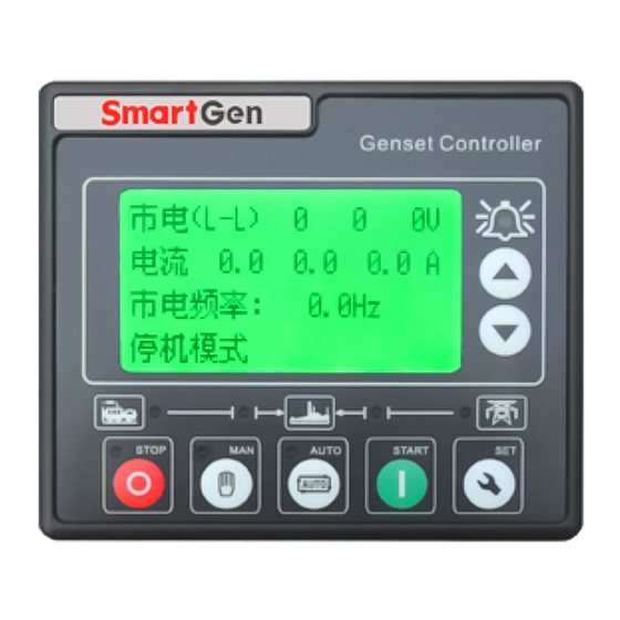
HGM400 Series Genset Controller
(HGM410/HGM420)
USER MANUAL
ZHENGZHOU SMARTGEN TECHNOLOGY CO.,LTD
Table of
Contents
Previous
Page
Next
Page
1
2
3
4
5
Advertisement
Table of Contents
Need help?
Do you have a question about the HGM400 Series and is the answer not in the manual?
Ask a question
Questions and answers
Related Manuals for Smartgen HGM400 Series
Controller Smartgen HGM410E User Manual
Hgm400e series genset controller (40 pages)
Controller Smartgen HGM400N Series User Manual
Genset controller (36 pages)
Controller Smartgen HGM400N Series User Manual
Genset controller (38 pages)
Controller Smartgen HGM410 User Manual
Genset controller (44 pages)
Controller Smartgen HGM420 User Manual
Genset controller (44 pages)
Controller Smartgen HGM4100LT User Manual
Genset controller (48 pages)
Controller Smartgen HGM4020DC User Manual
Genset controller (30 pages)
Controller Smartgen HGM410DC User Manual
Genset controller (33 pages)
Controller Smartgen HGM410C User Manual
Genset controller (34 pages)
Controller Smartgen HGM6100K Series Operating Manual
Automatic generator module (31 pages)
Controller Smartgen HGM6110U User Manual
Hgm6100u series automatic control controllers (39 pages)
Controller Smartgen HGM7220N Series User Manual
Genset controller (60 pages)
Controller Smartgen HGM501 User Manual
Genset controller (17 pages)
Controller Smartgen HGM9510 User Manual
Genset parallel (with genset) controller (68 pages)
Controller Smartgen HGM1790N User Manual
Genset controller (31 pages)
Controller Smartgen HGM7110DC User Manual
Dc genset controller (68 pages)
This manual is also suitable for:
Hgm420
Hgm410
Table of Contents
Save PDF
Print
Rename the bookmark
Delete bookmark?
Delete from my manuals?
Login
Sign In
OR
Sign in with Facebook
Sign in with Google
Upload manual
Upload from disk
Upload from URL


Need help?
Do you have a question about the HGM400 Series and is the answer not in the manual?
Questions and answers