Table of Contents
Advertisement
Advertisement
Table of Contents

Related Manuals for Smartgen HGM1790N


Summary of Contents for Smartgen HGM1790N
- Page 1 HGM1790N GENSET CONTROLLER USER MANUAL SMARTGEN (ZHENGZHOU) TECHNOLOGY CO., LTD.
- Page 2 SmartGen Technology at the address above. Any reference to trademarked product names used within this publication is owned by their respective companies. SmartGen Technology reserves the right to change the contents of this document without prior notice. Table 1 Software Version...
-
Page 3: Table Of Contents
SENSOR SETTINGS ........................26 10. COMMISSIONING ......................... 27 11. TYPICAL APPLICATION ....................... 28 12. INSTALLATION ..........................29 12.1. FIXING CLIPS ........................... 29 12.2. OVERALL DIMENSION ......................29 13. FAULT FINDING ..........................31 HGM1790N Genset Controller User Manual Page 3 of 31... -
Page 4: Overview
OVERVIEW HGM1790N genset controller is suit for single unit automation and monitoring control (also can be used for pumping unit). It can realize manual start/stop of genset, and it can also automatically start/stop genset by remote start signal. HGM1790N controller can supervise and... - Page 5 Digital regulation of all parameters - instead of analog regulation using conventional potentiometer, therefore, higher reliability and stability; □ Modular design, self-extinguishing ABS plastic enclosure and embedded installation way; small size and compact structure with easy mounting HGM1790N Genset Controller User Manual Page 5 of 31...
-
Page 6: Specification
IP55: When waterproof rubber gasket installed between the Protection Level controller and panel fascia. Attach AC2.2kV voltage between AC high voltage terminal and low Insulation Intensity voltage terminal (leak current below 3mA in 1 minute). Weight 0.18kg HGM1790N Genset Controller User Manual Page 6 of 31... -
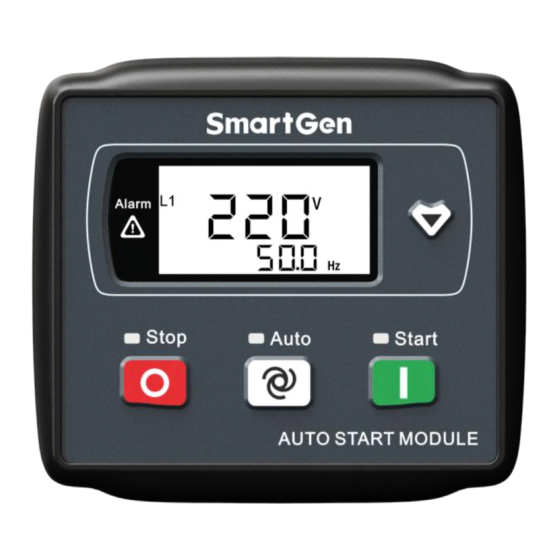
Page 7: Operation
OPERATION 4.1. FRONT PANEL DESCRIPTION Fig.1 HGM1790N Front Panel Indication 4.2. INDICATOR DESCRIPTION Stop status indicator light: genset in stop mode. Auto status indicator light: genset in auto mode. Manual start indicator light: genset in manual mode. Alarm indicator light: blink slowly (1 time/s) when warn alarm occurred; blink fast (5 times/s) when shutdown alarm occurred. -
Page 8: Panel Keys
Temperature Unit Low Oil Pressure Speed Unit (revolutions per minute) Fail to Start Active Power Unit Fail to Stop Voltage Unit Voltage Abnormal Percentage Over Voltage Under Voltage Over Current With Load HGM1790N Genset Controller User Manual Page 8 of 31... -
Page 9: Display Description
“OFF” means sensors are open circuit. When total running time is lower than 20000 hours, value before the decimal point means running hours and value after the decimal point means 1/10 hour. HGM1790N Genset Controller User Manual Page 9 of 31... -
Page 10: Auto Start/Stop Operation
(No.2~7 of Automatic Start Sequence for detail procedures). With high temperature, low oil pressure, over speed and abnormal voltage during generator running, controller can protect genset to stop quickly. HGM1790N Genset Controller User Manual Page 10 of 31... - Page 11 MANUAL STOP: Press can shut down the running genset. (Please refer to No.2~6 of Automatic Stop Sequence for detail procedures). HGM1790N Genset Controller User Manual Page 11 of 31...
-
Page 12: Protection
Controller sent alarms when generator current is higher than the preset value and lasts for over the Gen Over Current Shut Shut Alarm delay value (over current action is selected as “Shutdown”). HGM1790N Genset Controller User Manual Page 12 of 31... - Page 13 20s. Controller sent alarms when battery voltage is High Battery Volt Warn Warn Alarm higher than over voltage threshold and lasts for over 20s. HGM1790N Genset Controller User Manual Page 13 of 31...
-
Page 14: Wiring Connection
Connect to speed sensor, and shielded wire is Magnetic Pickup 0.5mm recommended. The other end of speed sensor is connected to B-. Gen Volt Monitoring 1.0mm Connect to generator voltage output port. (2A fuse is HGM1790N Genset Controller User Manual Page 14 of 31... - Page 15 Aux. Output 3 1.0 mm B+ is supplied by No.2 point, rated 1A. NOTE: Type-B USB port, which can be connected with PC software, is applied for parameter configuration and data monitoring. HGM1790N Genset Controller User Manual Page 15 of 31...
-
Page 16: Parameter Range And Definition
“ETS output time” is not 0. Tooth number of the engine is for judging of crank disconnect conditions Flywheel Teeth (1-300) and inspecting of engine speed. See the installation instructions. HGM1790N Genset Controller User Manual Page 16 of 31... - Page 17 When the temperature value of the external temperature sensor exceeds High (80-140)ºC this threshold, high temperature signal is Temperature sent. Detection starts after safety delay and only concerns external temperature HGM1790N Genset Controller User Manual Page 17 of 31...
- Page 18 (50-130) Percentage full-load current multiply over current percentage. Over Current When current with load exceeds preset (0-3600)s Delay value and stays so over delay time, over HGM1790N Genset Controller User Manual Page 18 of 31...
- Page 19 Sensor “8 Multiplex Level Sensor”. When crank disconnect condition Disconnect (0-20.0)s 0.0s including oil pressure, and engine oil Pressure Delay pressure and delay value are higher than HGM1790N Genset Controller User Manual Page 19 of 31...
- Page 20 Default Parameter Range Description Value set values, starter will be disconnected and oil engine crank successfully. (0-9) Aux. Output 1 Default: Idle Speed Output (0-9) Aux. Output 2 Default: ETS Output HGM1790N Genset Controller User Manual Page 20 of 31...
-
Page 21: Definable Contents Of Relay Outputs
Reserved Reserved Multiplex Level Sensor Parameter P44 ”Fuel Level Sensor” Input is active. HGM1790N Genset Controller User Manual Page 21 of 31... -
Page 22: Sensor Selection
The range of user-defined resistor type 6 Reserved 1 sensor is 0-6000Ω, by default “Not 7 Reserved 2 used” is selected Before selecting fuel level sensor type, digital input type must be set as 8. HGM1790N Genset Controller User Manual Page 22 of 31... -
Page 23: Conditions Of Crank Disconnect Selection
6) If not select generator frequency in crank disconnect setting, controller will not collect and display the relative electric quantity (can be used in water pump set); if not select speed in crank disconnect setting, the speed displayed in controller is calculated by generator signal. HGM1790N Genset Controller User Manual Page 23 of 31... -
Page 24: Controller Function Setting
Please set the generator frequency value as low as possible when cranking, in order to make the starter be separated quickly as soon as crank disconnect. g) Before selecting fuel level sensor type, it is necessary to set a configurable input port type as 8 first. HGM1790N Genset Controller User Manual Page 24 of 31... -
Page 25: Lcd Contast Adjustment
Generator Frequency + Speed + Oil Pressure” (generator frequency and speed are not 0), controller will automatic adjust generator flywheel teeth based on gen frequency and poles when simultaneous press keys for 0.5s. HGM1790N Genset Controller User Manual Page 25 of 31... -
Page 26: Sensor Settings
Fig.6 Sensor Curve Table 12 Normal Pressure Unit Conversion Table (pa) kgf/cm - - - 1.02x10 1x10 1.45x10 1kgf/cm 9.8x10 0.98 14.2 1bar 1x10 1.02 14.5 - - 1psi 6.89x10 7.03x10 6.89x10 HGM1790N Genset Controller User Manual Page 26 of 31... -
Page 27: Commissioning
(if idle run be set). During this time, please watch for engine’s running situations and AC generator’s voltage and frequency. If abnormal, stop genset and check all wires connection according to this manual. Any other questions please contact with SmartGen service personnel. HGM1790N Genset Controller User Manual Page 27 of 31... -
Page 28: Typical Application
TYPICAL APPLICATION Fig.7 HGM1790N Typical Application Diagram CAUTION: Crank and fuel output ports should be extended large capacity relays. CAUTION: When sensor port is configured as “high digital input is active”, hang in air means high electrical level; and power supply positive is prohibited to be connected. -
Page 29: Installation
□ BATTERY VOLTAGE INPUT HGM1790N series controller can suit for widely range of battery voltage DC(8~35)V. Negative of battery must be connected with the engine shell. Diameter of wire that connects from power supply to battery must be over 1.5mm . - Page 30 When controller had been installed in control panel, if need the high voltage test, please disconnect controller’s all terminal connections, in order to prevent high voltage into controller and damage it. HGM1790N Genset Controller User Manual Page 30 of 31...
-
Page 31: Fault Finding
Check fuel circuit and its connections; Check starting batteries; Crank not disconnect Check speed sensor and its connections; Refer to engine manual. Check starter connections; Starter no response Check starting batteries. _________________________________ HGM1790N Genset Controller User Manual Page 31 of 31...
Need help?
Do you have a question about the HGM1790N and is the answer not in the manual?
Questions and answers