
Related Manuals for Smartgen HGMS62


Summary of Contents for Smartgen HGMS62
- Page 1 HGMS62 SPLIT TYPE GENSET CONTROLLER USER MANUAL HGMS62D Display Module HGMS62M Master Control Module...
- Page 2 SmartGen Technology at the address above. Any reference to trademarked product names used within this publication is owned by their respective companies. SmartGen Technology reserves the right to change the contents of this document without prior notice. Table 1 – Software Version Date...
- Page 3 Indicates a procedure or practice, which, if not strictly observed, could result in CAUTION damage or destruction of equipment. Indicates a procedure or practice, which could result in injury to personnel or loss of life if not followed correctly. WARNING HGMS62 Split Type Genset Controller User Manual Page 3 of 58...
-
Page 4: Table Of Contents
4.3.3 AUTO STOP SEQUENCE ....................12 4.4 MANUAL START/STOP OPERATION ..................13 4.5 EMERGENCY START ........................ 13 5 HGMS62 BREAKER CONTROL PROCEDURE ................... 13 5.1 MANUAL TRANSFER PROCEDURE ..................13 5.2 AUTO TRANSFER PROCEDURE ....................14 6 PROTECTION ............................. 15 6.1 WARNING ALARMS ......................... - Page 5 14.14 SCANIA ..........................56 14.15 VOLVO EDC3 ......................... 56 14.16 VOLVO EDC4 ......................... 56 14.17 VOLVO-EMS2 ........................57 14.18 YUCHAI ..........................57 14.19 WEICHAI ..........................57 15 FAULT FINDING ..........................58 HGMS62 Split Type Genset Controller User Manual Page 5 of 58...
-
Page 6: Overview
OVERVIEW HGMS62 Genset Controller adopts split structure of “Master Control and Display”, integrating digital, intelligent and network techniques, is used for automatic control and monitoring system of genset. It can carry out functions of automatic start/stop, data measurement, alarm protection and “four remote”... - Page 7 — HGMS62D is fixed by metal fixing clips and HGMS62M is fixed with screws; — Modular design and pluggable terminal, compact structure and easy installation; — Personalized startup interface, customers can define it as demand and display via HGMS62D. HGMS62 Split Type Genset Controller User Manual Page 7 of 58...
-
Page 8: Specification
Crank Relay Output 10A DC24V supply output (relay output, pluggable) Digital Output 1 7A DC24V supply output (relay output) Digital Output 2 7A AC250V volts free output (relay output) HGMS62 Split Type Genset Controller User Manual Page 8 of 58... - Page 9 HGMS62D: IP65 HGMS62M: IP20 Apply AC2.2kV voltage between high voltage terminal and low voltage Insulation Strength terminal. The leakage current is not more than 3mA within 1min. HGMS62D: 0.5kg Weight HGMS62M: 1.0kg HGMS62 Split Type Genset Controller User Manual Page 9 of 58...
-
Page 10: Operation
Return to homepage when pressing this key in main interface; Return to the previous interface when pressing this key in parameters Home/Return setting interface; Press this key more than 3s to reset trip alarm. HGMS62 Split Type Genset Controller User Manual Page 10 of 58... -
Page 11: Controller Panel
NOTE3: Mains normal indicator: always illuminates in normal running, flashes in abnormal running; distinguishes in no mains. NOTE4: When mains is disabled, mains normal indicator distinguishes, mains close/open key is inactive at the same time. HGMS62 Split Type Genset Controller User Manual Page 11 of 58... -
Page 12: Automatic Start/Stop Operation
“Warming Up Delay” (if configured). When mains abnormal starts or HGMS62 remote start (on-load) inputs, if “Warming Up Delay” is over, the indicator will illuminate if gen is normal. If genset voltage and frequency reach the load requirement, the closing relay outputs, genset is taking load and indicator illuminates, genset enters normal running;... -
Page 13: Manual Start/Stop Operation
If gen takes load, gen breaker will open, when open delay is over, mains breaker closes. If open detection is enabled, mains on-load is transferred to gen on-load, press mains HGMS62 Split Type Genset Controller User Manual Page 13 of 58... -
Page 14: Auto Transfer Procedure
NOTE2: When ATS with interposition is used, open detection can be enabled or disabled, if enabled, please configure open output. NOTE: When AC contactor is used, open detection enable is recommended. HGMS62 Split Type Genset Controller User Manual Page 14 of 58... -
Page 15: Protection
17 Gen Loss of Phase When gen losses phase, controller will send warning alarm signal. 18 Gen Reverse Phase When gen phase sequence is wrong, controller will send warning alarm HGMS62 Split Type Genset Controller User Manual Page 15 of 58... - Page 16 When aux. sensor 2 value is lower that threshold, controller will send 32 Aux. Sensor 2 Low warning alarm signal. When digital warning input is active, controller will send warning alarm 33 Input Warning signal. HGMS62 Split Type Genset Controller User Manual Page 16 of 58...
-
Page 17: Shutdown Alarms
When oil pressure sensor is open and open action selects “Shutdown”, Open controller will send shutdown alarm signal. When oil pressure value is lower than threshold, controller will send 17 Low Oil Pressure shutdown alarm signal. HGMS62 Split Type Genset Controller User Manual Page 17 of 58... -
Page 18: Trip And Stop Alarms
“Trip and Stop”, controller will send trip and stop alarm signal. When input port is configured as “Trip and Stop” and active, controller Input Trip and Stop will send trip and stop alarm signal. HGMS62 Split Type Genset Controller User Manual Page 18 of 58... -
Page 19: Trip Alarms
“Trip”, controller will send trip alarm signal. When input port is configured as “Trip” and active, controller will send Input Trip trip alarm signal. HGMS62 Split Type Genset Controller User Manual Page 19 of 58... -
Page 20: Connections
Relay 250V AC volts free (N/O) output (pluggable), rated 10A. Aux. Relay Output 3 1.5mm Relay common point. Relay 250V AC volts free (N/C) output (pluggable), Aux. Relay Output 4 1.5mm rated 10A. HGMS62 Split Type Genset Controller User Manual Page 20 of 58... - Page 21 1.5mm terminal 10 of connector B has been connected inside controller. Connect external actuator. This terminal and ACT2 1.5mm terminal 7 of connector B has been connected inside controller. HGMS62 Split Type Genset Controller User Manual Page 21 of 58...
- Page 22 Main terminal 26. Connect to speed sampling terminal of ESC. 1.5mm The controller inside has connected to B-. MP2 Speed Output 0.5mm The controller inside has connected to B-. HGMS62 Split Type Genset Controller User Manual Page 22 of 58...
-
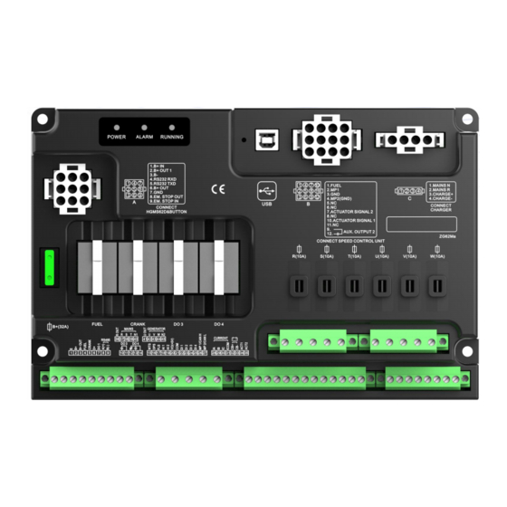
Page 23: Hgms62D Controller Rear Panel
1.5mm Connect to charger B-. NOTE: USB ports are programmable parameter ports; user can directly program via PC. HGMS62D CONTROLLER REAR PANEL Fig.3 – HGMS62D Controller Rear Panel Drawing HGMS62 Split Type Genset Controller User Manual Page 23 of 58... -
Page 24: Hgms62 Wire Harness Description
0.5mm to terminal 4 GND. 1.5mm Connect negative of controller power. 1.5mm 1.5mm Connect positive of controller power. HGMS62 WIRE HARNESS DESCRIPTION Table 12 – HGMS62 Wire Harness Description Harness Port Harness Length Diagram Function Cable Size XS-HGMS62DM XS-HGMS62DM-S MAINS N 1.0mm... -
Page 25: Parameter Range And Definition
Confirm time for over freq. detection. Setting (0-200)% Confirm time for over freq. detection. (0-3600)s Confirm time for under freq. detection. Loss of Phase Setting (0-1) 0: Disable; 1: Enable. Reverse Phase Setting (0-1) HGMS62 Split Type Genset Controller User Manual Page 25 of 58... - Page 26 2: Aux. Sensor 2; 3: Oil Pressure Sensor; 4: Fuel Level Sensor. Sensor Set Value (0-1000) Pre-fuel output time before starter is Fuel Output Time (0-3600)s powered on. Engine Setting Type (0-69) Default: 0 Non-ECU. HGMS62 Split Type Genset Controller User Manual Page 26 of 58...
- Page 27 Return value: battery rated volt PCT. Confirm time for battery over volt (0-3600)s detection. (0-1) 0: Disable; 1: Enable. Under Volt Warning (0-200)% Set value: battery rated volt PCT. HGMS62 Split Type Genset Controller User Manual Page 27 of 58...
- Page 28 (0-1) 0: Controller; 1: ECU Engine Temp (0-1) 0: Controller; 1: ECU Sampling OP Sampling (0-1) 0: Controller; 1: ECU Battery Under Volt (0-1) 0: Disable; 1: Enable. Start HGMS62 Split Type Genset Controller User Manual Page 28 of 58...
- Page 29 Set value: gen rated voltage PCT. Shutdown Confirm time for gen over voltage (0-3600)s shutdown detection. Under Volt (0-1) 0: Disable; 1: Enable. Shutdown (0-200)% Set value: gen rated voltage PCT. HGMS62 Split Type Genset Controller User Manual Page 29 of 58...
- Page 30 Generator rated current, used for judging Rated Current (5-6000)A load current. Generator rated power, used for judging Rated Power (0-6000)kW load power. Over Current Enable (0-1) 0: Disable; 1: Enable. HGMS62 Split Type Genset Controller User Manual Page 30 of 58...
- Page 31 0: Disable; 1: Enable. Open Detection (0-1) Fast Trip in Mains (0-1) 0: Disable; 1: Enable. Abnormal Module Setting 0: Stop Mode; 1: Manual Mode; 2: Auto Power-on Mode (0-2) Mode. HGMS62 Split Type Genset Controller User Manual Page 31 of 58...
- Page 32 When external temperature value is Over Low Warning lower than it, low temp warning will be (-50-300)ºC issued. This value only begins to judge after safety delay is over. HGMS62 Split Type Genset Controller User Manual Page 32 of 58...
- Page 33 Return value: when external oil pressure (0-1000)kPa value is more than or equal to this value, alarm is removed. Confirm time for over low oil pressure (0-3600)s warning detection. HGMS62 Split Type Genset Controller User Manual Page 33 of 58...
- Page 34 0: Close; 1: Open. Input Port 2 Setting High temperature shutdown input. See Content Set (0-50) Table 15. Active Type (0-1) 0: Close; 1: Open. Input Port 3 Setting HGMS62 Split Type Genset Controller User Manual Page 34 of 58...
- Page 35 (0-1) 0: Normally Open; 1: Normally Close. Output Port 4 Setting Content Set (0-239) Mains closed output. See Table 14. Output Type (0-1) 0: Normally Open; 1: Normally Close. HGMS62 Split Type Genset Controller User Manual Page 35 of 58...
-
Page 36: Defined Contents Of Auxilary Output 1-4
Cooler Control sensor. Pre-fuel Output Action in crank-safety running. Outputs in crank process, if there is no gen frequency in high Excitation Output speed running, it outputs 2s again. HGMS62 Split Type Genset Controller User Manual Page 36 of 58... - Page 37 Action when charging genset failure warning occurs. Reserved Reserved ECU Key Switch Action after fuel outputs 3s, stops after ETS. ECU Warning Alarm Indicate that ECU sends a warning alarm signal. HGMS62 Split Type Genset Controller User Manual Page 37 of 58...
- Page 38 Action when gen over frequency warning occurs. Gen Over Freq. Shut. Action when gen over frequency shutdown occurs. Gen Over Volt Warn Action when gen over voltage warning occurs. HGMS62 Split Type Genset Controller User Manual Page 38 of 58...
- Page 39 Action when aux. sensor 2 low warning occurs. Aux. Sensor 2 High Shut Action when aux. sensor 2 high shutdown occurs. Aux. Sensor 2 Low Shut Action when aux. sensor 2 low shutdown occurs. HGMS62 Split Type Genset Controller User Manual Page 39 of 58...
-
Page 40: Custom Period Output
Output port 1 inactive, custom output period is not outputting 8.2.3 CUSTOM COMBINATION OUTPUT Custom combination output is composed by 3 parts, or condition output S1, or condition output S2, and condition output S3. HGMS62 Split Type Genset Controller User Manual Page 40 of 58... -
Page 41: Defined Contents Of Digital Input 1-9
Under speed, under frequency and under voltage are not protected Idle Mode in this mode. After generator is normal running in auto mode, when input is Inhibit Auto Stop active, genset auto stop function is inhibited. HGMS62 Split Type Genset Controller User Manual Page 41 of 58... - Page 42 When engine type is 35 MTSC1 and is active, the target engine Drop Speed Pulse speed decreases 50RPM. Idle Pulse Input When engine type is 35 MTSC1 and is active, the target engine HGMS62 Split Type Genset Controller User Manual Page 42 of 58...
-
Page 43: Sensor Selection
4 CURTIS Defined input resistance range is Pressure 5 VOLVO-EC 0Ω~6000Ω, factory default is (Pressure) Sensor 6 DATCON SGD sensor. 7 SGX 8 SGD 9 SGH 10 PT100 11 SUZUKI HGMS62 Split Type Genset Controller User Manual Page 43 of 58... -
Page 44: Crank Disconnect Conditions Selection
If generator frequency has not been selected, controller will not measure and display the relative parameters (can be applied to the pump set); if speed has not been selected, the rotating speed will be calculated by the generating signal. HGMS62 Split Type Genset Controller User Manual Page 44 of 58... -
Page 45: Parameter Setting
CONTROLLER INFORMATION This interface can display controller develop information, such as software version, hardware version, issue date. Press in this interface can display digital input port and output port status. HGMS62 Split Type Genset Controller User Manual Page 45 of 58... -
Page 46: Date And Time
Table 18 – Normal Pressure Unit Conversion Item 1N/m (pa) 1kgf/cm 1bar (1b/in ) psi - - - 1.02x10 1x10 1.45x10 1kgf/cm 9.8x10 0.98 14.2 1bar 1x10 1.02 14.5 - - 1psi 6.89x10 7.03x10 6.89x10 HGMS62 Split Type Genset Controller User Manual Page 46 of 58... -
Page 47: Commissioning
ATS is controlled to genset on-load. If not, please check all connections according to this manual. — If there are any other questions, please contact SmartGen’s service. HGMS62 Split Type Genset Controller User Manual Page 47 of 58... -
Page 48: Typical Application
12 TYPICAL APPLICATION Fig.5 – HGMS62 Typical Application Diagram Fig.6 – HGMS62CAN Typical Application Diagram HGMS62 Split Type Genset Controller User Manual Page 48 of 58... - Page 49 Fig. 7 – Single Phase 2 Wire Diagram Fig. 8 – 2 Phase 3 Wire Diagram HGMS62 Split Type Genset Controller User Manual Page 49 of 58...
-
Page 50: Installation
Fig. 9 – HGMS62D Case and Overall Dimensions Unit: mm Fig.10 – HGMS62M Case and Overall Dimensions HGMS62 controller can be applicable to (8~35) VDC battery voltage. Battery negative must be HGMS62 Split Type Genset Controller User Manual Page 50 of 58... - Page 51 AC Input HGMS62 controller must externally connect to current transformer; CT secondary current must be 5A. Besides, the phase of CT and input voltage must be correct, or the sampling current and active power may be incorrect.
-
Page 52: Connections Of Controller With J1939 Engine
Table 24 – 3 Pins Data Link Connector Terminals of controller 3 pins data link connector Remark CAN(H) Using impedance 120Ω connecting line. CAN(L) Using impedance 120Ω connecting line. Engine type: CUMMINS-ISB. HGMS62 Split Type Genset Controller User Manual Page 52 of 58... -
Page 53: Cummins Qsx15-Cm570
Engine OEM connector Remark Fuel relay output Crank relay output Connect to starter coil directly. CAN(H) Using impedance 120Ω connecting line. CAN(L) Using impedance 120Ω connecting line. Engine type: common J1939. HGMS62 Split Type Genset Controller User Manual Page 53 of 58... -
Page 54: Cummins Qsz13
Terminals of controller 21 pins connector Remark Fuel relay output G, J Crank relay output Using impedance 120Ω connecting line. CAN(H) Using impedance 120Ω connecting line. CAN(L) Engine type: JOHN DEERE. HGMS62 Split Type Genset Controller User Manual Page 54 of 58... -
Page 55: Mtu Adec (Smart Module)
Fuel relay output 1, 10, 15, 33, 34 Crank relay output Connect to starter coil directly. CAN(H) Using impedance 120Ω connecting line. CAN(L) Using impedance 120Ω connecting line. Engine type: PERKINS. HGMS62 Split Type Genset Controller User Manual Page 55 of 58... -
Page 56: Scania
Terminal 14. Fuse is 16A. Crank relay output Connect to starter coil directly. Connected to battery negative. CAN(H) Using impedance 120Ω connecting line. CAN(L) Using impedance 120Ω connecting line. Engine type: VOLVO-EDC4. HGMS62 Split Type Genset Controller User Manual Page 56 of 58... -
Page 57: Volvo-Ems2
Using impedance 120Ω connecting line. CAN(L) 1.34 Using impedance 120Ω connecting line. Engine type: GTSC1. NOTE: If there is any problem in controller and ECU communication, please contact SmartGen service. HGMS62 Split Type Genset Controller User Manual Page 57 of 58... -
Page 58: Fault Finding
RS485 Failure Check if A and B of RS485 is connected reversely; Check if PC COM port is damaged; 120Ω resistance between RS485’s A and B is recommended. _________________________________ HGMS62 Split Type Genset Controller User Manual Page 58 of 58...
Need help?
Do you have a question about the HGMS62 and is the answer not in the manual?
Questions and answers
How to change the phase rotation on a genset smart gen conteoller HGMS62 and where can I get the software