Table of Contents
Advertisement
Advertisement
Table of Contents

Related Manuals for Smartgen HGM6100K Series


Summary of Contents for Smartgen HGM6100K Series
- Page 1 HGM6100K Series Automatic Generator Module OPERATING MANUAL Smartgen Electronics...
- Page 2 Smartgen Electronics at the address above. Any reference to trademarked product names used within this publication is owned by their respective companies. Smartgen electronics reserves the right to change the contents of this document without prior notice. Software Version Version Date Note 2009-10-10 Original release.
-
Page 3: Table Of Contents
HGM6100K Series Automatic Generator Module CONTENT SUMMARY ..................4 PERFORMANCE AND CHARACTERISTICS ....... 4 SPECIFICATION ................6 OPERATION .................. 7 4.1 KEY FUNCTION ..................7 4.2 AUTOMATIC OPERATION ..............7 4.3 MANUAL OPERATION ................9 PROTECTION ................9 5.1 WARNING ....................9 5.2 SHUTDOWN ALARM ................ -
Page 4: Summary
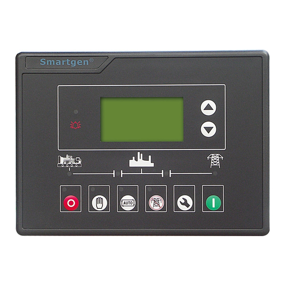
HGM6100K Series Automatic Generator Module 1 SUMMARY HGM6100K series Genset controller integrating digital, intelligent and network techniques is used for automatic control system of diesel generator. It can carry out functions including automatic start/stop, data measure and alarm protective. The controller uses LCD display, optional Chinese, English, Spanish and Russian display interface with operation easy and reliable. - Page 5 HGM6100K Series Automatic Generator Module Load Power Current IA, IB, IC Active power KW Inactive power KVar Apparent power KVA Power factor Cos Accumulate total gens power kWh ■ Mains have over voltage, under voltage, loss phase function; Gens have over voltage, under voltage, over frequency, under frequency, over current function;...
-
Page 6: Specification
HGM6100K Series Automatic Generator Module connection terminals, flush type installation, compact structure, easy installation. 3 SPECIFICATION Operating Voltage DC8.0V to 35.0V, Continuous <3W(Standby mode: ≤2W) Power Consumption AC voltage Input Range 3-Phase 4 Wire 15V AC - 360 V AC (ph-N) -
Page 7: Operation
HGM6100K Series Automatic Generator Module 4 OPERATION 4.1 KEY FUNCTION Can stop generator under mode of Manual/Auto; Can reset alarming under Stop; To test panel indicators are OK or not, pressing this Stop/ Reset key at least 3 seconds; During stopping process, press this again can stop generator immediately. - Page 8 HGM6100K Series Automatic Generator Module e) When preheat relay is over, oil relay is outputting 1s and then start relay-output; if genset fails in starting during “cranking time”, the oil and start relays stop outputting and enters into “crank rest time” and wait for next attempt.
-
Page 9: Manual Operation
HGM6100K Series Automatic Generator Module 4.3 MANUAL OPERATION 1) HGM6120KC, Auto starts mode is active when press and its indicator is , then controller under “Manual Test Mode” and its illuminating. Press indicator is illuminating. Under the both modes, press to start genset, and it can automatic detect start successfully and accelerate to Hi-speed running. -
Page 10: Shutdown Alarm
HGM6100K Series Automatic Generator Module Type Description When controller detected the current of genset is over Gens Over than threshold and over current delay set as 0, Current controller will send warning alarm signal and it will be displayed in LCD When generator not stops after the “stop relay”... -
Page 11: Connecting Terminal
HGM6100K Series Automatic Generator Module Type Description alarm set for alarming, it will send a stop alarm signal and it will be displayed in LCD When controller detected genset speed is 0 or delay is Speed signal not 0, it will send a stop alarm signal and it will be... - Page 12 HGM6100K Series Automatic Generator Module Description of terminal blocks connection Function Description DC Plant Supply input System DC negative input. (Battery 2.5mm (-ve) Negative). System DC positive input. (Battery DC Plant Supply input 2.5mm Positive). (Recommended Maximum (+ve) Fuse 20A) Plant Supply +ve.
- Page 13 HGM6100K Series Automatic Generator Module Function Description input Magnetic pickup +ve Connect to Magnetic Pickup device. Magnetic pickup -ve Connecting water/cylinder temperature resistance type Temp. sensor input Reference sensor. table 4 Oil pressure input Connect to oil pressure sensor. Liquid level input Connect to liquid Level sensor.
-
Page 14: Parameter Range And Define
HGM6100K Series Automatic Generator Module 7 PARAMETER RANGE AND DEFINE All parameters of HGM6100K series are as following: 7.1 PARAMETERS TABLE (TABLE 1) Parameter Range Default Description Mains volt (0-3600)s normal delay Mains transient delay, suited for ATS (automatic Mains volt transfer switch). - Page 15 HGM6100K Series Automatic Generator Module Parameter Range Default Description When engine start success, most of cranking numbers. When reach Number of crank (1-10)times setting crank numbers, controller send out start fail signal. Preheat time (0-300)s The starter adds the time...
- Page 16 HGM6100K Series Automatic Generator Module Parameter Range Default Description When the engine speed is over than the point and Over speed (0-6000)RPM 1710 hold great than 2 seconds, generator over speed is active. When generator freq. is than point, Gens under freq (0-75.0)Hz...
- Page 17 HGM6100K Series Automatic Generator Module Parameter Range Default Description When speed is zero and remain for the delay, send Lose speed (0-20.0)s out shutdown alarm. When delay the delay is zero, send out warning alarm. During generator running, when charge...
- Page 18 HGM6100K Series Automatic Generator Module Parameter Range Default Description When the fuel level higher Fuel pump off than the set value and for (0-100)% threshold 10 seconds, the output fuel pump off signal. Digit Output1 set (0-17) Energized to stop...
-
Page 19: Programmable Output 1-4 Table (Table 2)
HGM6100K Series Automatic Generator Module Parameter Range Default Description When generator frequency Freq disconnect (10-30)Hz is over than this point, starter will disconnect. When engine oil pressure OP disconnect (0-400)kPa is over than this point, starter will disconnect. Default, when temperature High temp. - Page 20 HGM6100K Series Automatic Generator Module Content Description The designated programmable output relay will energize when a stop signal has been ETS solenoid hold activated. The output will remain energized for pre-set timer once the engine has come to a complete stop, then de-energizes.
-
Page 21: Programmable Digit Input 1-5 Table
HGM6100K Series Automatic Generator Module Content Description Reserved Reserved Reserved Reserved 7.3 PROGRAMMABLE DIGIT INPUT 1-5 TABLE (ALL IS VALID WHEN CONNECT GRAND (B-) (TABLE 3) Content Description Not used High Temp. alarm input After the end of the delay in the safe... -
Page 22: Sensor Selection (Table 4)
HGM6100K Series Automatic Generator Module Content Description active and a remote start signal/mains failure occurs the HGM6110/20K will not give a start command to the generator. If this input signal is then removed, the HGM6110/20K will operate as if a remote start/mains failure has occurred, starting and loading the generator. -
Page 23: Conditions Of Crank Succeed (Table 5)
HGM6100K Series Automatic Generator Module Content Description 5 Reserved 2 7.5 CONDITIONS OF CRANK SUCCEED (TABLE 5) Content Magnetic pickup sensor Generator Magnetic pickup sensor + Generator Magnetic pickup sensor + Oil pressure Generator + Oil pressure Generator + Magnetic pickup sensor + Oil pressure... -
Page 24: Parameter Setting
HGM6100K Series Automatic Generator Module 8 PARAMETER SETTING After controller powered on, press to enter into the parameters setting menu: 1 Set Parameters. 2 Information. 3 Set Languages. ■ Set parameters When entering password, entering "1234" can set the item 1 to 38 in the table (parameters table [Table 1]), entering "0318"... -
Page 25: Sensor Selection
HGM6100K Series Automatic Generator Module ■ Set language User may set display interface language as Chinese, English, Spanish and Russian. Note: Press the key will exit setting interface at any time. 9 SENSOR SELECTION 1. When the choice sensor, the sensor to standard curve will call. If factory set... -
Page 26: Commissioning
HGM6100K Series Automatic Generator Module Common units' conversion table 1N/m (pa) 1kgf/cm 1bar (1b/in ) psi 1.02×10 1×10 1.45×10 1kgf/cm 9.8×10 0.98 14.2 1bar 1×10 1.02 14.5 1psi 6.89×10 7.03×10 6.89×10 10 COMMISSIONING Before operation, inspections that are recommended as follows should be carried out: a. -
Page 27: Typical Application
HGM6100K Series Automatic Generator Module the operation situation of engine and the voltage and frequency of the AC generator. If there is abnormal, stop the generator, then check connections of each part according to this handbook; g. Select automatic state through front panel, then switch on the mains voltage,... - Page 28 HGM6100K Series Automatic Generator Module HGM6120KC Typical wiring diagram Single phase 2 wires (HGM6120KC) 2-phase 3 wires (HGM6120KC) Note: Recommend that the output of crank and Fuel expand high capacity relay. HGM6100K Series Automatic Generator Module ISSUE 2011-04-12 Version 1.6...
-
Page 29: Installation
1) Battery voltage input HGM6100K series controller can be applicable to (8-35)VDC battery voltage environment, battery anode must be reliable connect engine shell B + and B- controller power battery anode and cathode connections is not less than 2.5, if... -
Page 30: Fault Finding
HGM6100K Series Automatic Generator Module other equipment. 4) Alternating current input HGM6100K series controller to external input current transformer, electric current transformer side must be 5A, while the current transformers for phases and the phase of the input voltage must be correct, otherwise the current and sampling the active power may be incorrect. - Page 31 HGM6100K Series Automatic Generator Module Symptom Possible Remedy Check wiring of fuel solenoid. Check starting batteries. Crank no success Check speed sensor and its connections. Refer to engine manual. Check wiring of fuel solenoid. Check fuel. Check battery supply. Check battery supply is present on the Fuel Crank failure output of the module.
Need help?
Do you have a question about the HGM6100K Series and is the answer not in the manual?
Questions and answers