Table of Contents
Advertisement
Quick Links
Advertisement
Table of Contents

Related Manuals for Smartgen HGM4020DC


Summary of Contents for Smartgen HGM4020DC
- Page 1 HGM4020DC GENSET CONTROLLER USER MANUAL SMARTGEN (ZHENGZHOU) TECHNOLOGY CO., LTD.
-
Page 2: Table Of Contents
HGM4020DC GENSET CONTROLLER USER MANUAL CONTENT 1 OVERVIEW ............................4 2 PERFORMANCE AND CHARACTERISTICS ..................4 3 SPECIFICATION OPERATION ......................6 4 OPERATION ............................7 KEY FUNCTION........................7 CONTROLLER PANEL ......................8 AUTO START/STOP OPERATION ..................8 4.3.1 ILLUSTRATION ......................... 8 4.3.2 AUTO START SEQUENCE ....................... -
Page 3: Overview
HGM4020DC GENSET CONTROLLER USER MANUAL OVERVIEW HGM4020DC genset controller is specially designed for mobile communication base station, and its functions are completely followed by the actual situation of the mobile station. It not only fits with auto start/stop genset function in multiple boot conditions, data measurement function, alarm protection... - Page 4 HGM4020DC GENSET CONTROLLER USER MANUAL — Fits with switches to control rectifiers, and functions of setting output voltage and current; — Multiple crank disconnect conditions (speed sensor, generating and oil pressure) can be selected; — Access monitoring function, which can provide security for the machine room;...
-
Page 5: Specification Operation
HGM4020DC GENSET CONTROLLER USER MANUAL SPECIFICATION OPERATION Table 2 – Technical Parameters Items Contents Operating Voltage DC48V continuous; Range (20-65)V; <3W (standby ≤2W) Power Consumption Alternator Volt Input Range 3Phase 4Wire 15V AC - 360 V AC (ph-N) 3Phase 3Wire... -
Page 6: Operation
HGM4020DC GENSET CONTROLLER USER MANUAL OPERATION 4.1 KEY FUNCTION Table 3 - Key Function Description Icon Function Description Stop running generator in Auto/Manual mode; In case of alarm condition, pressing the button will reset alarms; In stop mode, pressing and holding the button for 3 seconds will Stop/ Reset test indicator lights (lamp test);... -
Page 7: Controller Panel
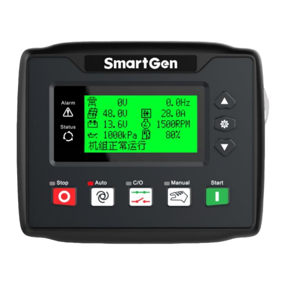
HGM4020DC GENSET CONTROLLER USER MANUAL 4.2 CONTROLLER PANEL Fig.1 - HGM4020DC Front Panel Indication NOTE: Part of indicator lights illustration: Alarm Indicators: slowly flash when warning alarms occur; fast flash when shutdown alarms occur; light is off when no alarms occur. -
Page 8: Auto Stop Sequence
HGM4020DC GENSET CONTROLLER USER MANUAL 4.3.3 AUTO STOP SEQUENCE a) If pre-set start conditions cannot be satisfied, “stop delay x s” will be started. b) When stop delay is over, “cooling time x s” is started, and rectifier output is closed;... -
Page 9: Mains Have Rules
HGM4020DC GENSET CONTROLLER USER MANUAL Optional stop contions are as below: 0: Pile Volt is higher than the upper limit and load current is lower than the lower limit; 1: Pile volt is higher than the upper limit; 2: Load current is lower than the lower limit;... - Page 10 HGM4020DC GENSET CONTROLLER USER MANUAL Type Description When the controller detects that the oil pressure sensor is open circuit and Oil Sensor Open the action selects “Warning”, it will initiate a warning alarm and the Warn corresponding alarm information will be displayed on LCD.
- Page 11 HGM4020DC GENSET CONTROLLER USER MANUAL Type Description If the config. sensor 2 is set as level sensor, when the controller detects that the level sensor is open circuit and the action selects “Warn”, it will Level 3 Open Warn initiate a warning alarm and the corresponding alarm information will be displayed on LCD.
-
Page 12: Shutdown Alarms
HGM4020DC GENSET CONTROLLER USER MANUAL 5.2 SHUTDOWN ALARMS When controller detects shutdown alarm, it will immediately control rectifiers to stop outputting and stop the genset, and the corresponding alarm information will be displayed on LCD. Table 7 – Shutdown Alarms... - Page 13 HGM4020DC GENSET CONTROLLER USER MANUAL Type Description corresponding alarm information will be displayed on LCD. When controller detects temp. sensor, which connects to programmable sensor 1, is open circuit, and the action selects “shutdown”, it will send Temp 1 Open...
-
Page 14: Trip And Stop Alarms
HGM4020DC GENSET CONTROLLER USER MANUAL 5.3 TRIP AND STOP ALARMS When controller detects trip and stop alarms, it will immediately control rectifiers to stop outputting, and stop the genset after cooling time. Table 8 – Trip and Stop Alarms Type... - Page 15 HGM4020DC GENSET CONTROLLER USER MANUAL Table 9 –Terminal Wire Connection Function Cable Size Remark 1.0mm Ground connected terminal for anti-thunder; RS485+ 0.5mm Communication terminal for connecting remote monitoring device; RS485- 0.5mm Resistance-120Ω shielding wire is recommended; single end of which shall be ground connected.
-
Page 16: Scopes And Definitions Of Programmable Parameters
HGM4020DC GENSET CONTROLLER USER MANUAL SCOPES AND DEFINITIONS OF PROGRAMMABLE PARAMETERS 7.1 CONTENTS AND SCOPES OF PARAMETERS Table 10 - Parameters Settings and Scope Items Range Default Description Mains 0: 3 Phase, 4 Wire(3P4W); 1: 2 Phase, 3 Wire (2P3W);... - Page 17 HGM4020DC GENSET CONTROLLER USER MANUAL Items Range Default Description Engine Tooth number of the engine, it is for judging Flywheel Teeth (10.0-300.0) 118.0 starter crank disconnect conditions and inspecting engine speed. When engine speed has fallen below the set value and delay time is expired, “Under...
- Page 18 HGM4020DC GENSET CONTROLLER USER MANUAL Items Range Default Description When generating voltage is higher than this value, then it is considered that over voltage Over Volt Warn (3.0-99.9)V 58.0 is established, and meanwhile warning alarm is initiated. When it is set to 620V, warning signal shall not be detected;...
- Page 19 HGM4020DC GENSET CONTROLLER USER MANUAL Items Range Default Description When the fuel level of the external sensor falls below the set value (always detect), “low fuel level” shutdown alarm is initiated. If Low Level Shutdown (0-100)% it is configured as 0, “low fuel level” alarm signal will not be initiated.
- Page 20 HGM4020DC GENSET CONTROLLER USER MANUAL Items Range Default Description (0-400) ℃ open/close is based on the values. Fan Off Temp Aux. Sensor 2 0: Digital input 6; 1: Temperature sensor; Sensor Type (0-3) 2: Oil pressure sensor; 3: Fuel level sensor;...
- Page 21 HGM4020DC GENSET CONTROLLER USER MANUAL Items Range Default Description active to action confirm. Factory default: not used, for details please (0-31) see Table 12. Input 6 Setting (0-1) 0: close to activate; 1: open to activate. It is time from detection of the input port is (0-20.0)s...
-
Page 22: Definable Content List Of Programmable Output Ports 1-5
HGM4020DC GENSET CONTROLLER USER MANUAL Items Range Default Description (0-30000)min Time(Minute) Duration time Mains Abnormal And Pile Low Volt Start Start Set (0-1) 0: Not Start; 1: Start 0: Pile Volt High and Current Low 1: Pile Volt High Stop Condition... - Page 23 HGM4020DC GENSET CONTROLLER USER MANUAL Items Function Description Preheat Control Close before start and open before power up; Raise Speed Action while in hi-speed warming up running period. Drop Speed Action while in the period time from stop idle speed to wait for stop.
-
Page 24: Definable Contents Of Programmable Input Ports 1-7
HGM4020DC GENSET CONTROLLER USER MANUAL 7.3 DEFINABLE CONTENTS OF PROGRAMMABLE INPUT PORTS 1-7 Table 12 - Definable Contents of Programmable Inputs 1~7(Ground connected (B-) is active.) Items Function Description Not Used Input port is inactive. If input port is active, “audible alarm” output will be inhibited. -
Page 25: Selection Of Sensors
HGM4020DC GENSET CONTROLLER USER MANUAL 7.4 SELECTION OF SENSORS Table 13 – Sensors Selection Items Content Remark 0 Not used 1 Defined Curve 2 VDO 3 SGH 4 SGD 5 CURTIS Defined resistance range is Temperature Sensor 6 DATCON 0Ω~999.9Ω. -
Page 26: Conditions Of Crank Disconnect Selection
HGM4020DC GENSET CONTROLLER USER MANUAL 7.5 CONDITIONS OF CRANK DISCONNECT SELECTION Table 14 – Crank Disconnect Conditions Setting Content Speed Gen frequency Speed + Gen frequency Speed +Oil pressure Gen frequency + Oil pressure Speed + Gen frequency + Oil pressure Oil pressure There are 3 conditions to make starter separate with engine;... -
Page 27: Controller Information
8.5 MAINTENANCE It needs to input password at entering into the maintenance interface, default is 0 (if password is changed, please contact with SmartGen service personnel or sales personnel). Setting maintenance parameters will refresh maintenance time. NOTE: Refresh maintenance time and enter into the next maintenance period in maintenance interface when “Maintenance Due Alarm”... -
Page 28: Sensor Setting
(if configured). During this time, please watch for engine’s running situation and AC generator’s voltage and frequency. If something abnormal occurs, stop genset and check all wire connections according to this manual. — If there is any other question, please contact SmartGen’s service. HGM4020DC Genset Controller Version 1.0... -
Page 29: Typical Application
HGM4020DC GENSET CONTROLLER USER MANUAL 11 TYPICAL APPLICATION Fig. 3 - Typical Application Drawing Fig. 4 - Single Phase 2-Wire Connection Diagram Fig. 5 - 2-Phase 3-Wire Connection Diagram NOTE: Expand relay with high capacity in start and fuel output is needed. -
Page 30: Overall Dimension
12.2 OVERALL DIMENSION Fig.6 - Overall Dimensions HGM4020DC controller is applicable for 48VDC battery voltage environment. Negative of battery must be connected with the engine shell. Diameter of wire that connects controller power B+/B- with battery positive/negative mustn’t be less than 2.5mm .
Need help?
Do you have a question about the HGM4020DC and is the answer not in the manual?
Questions and answers