
Subscribe to Our Youtube Channel
Related Manuals for Smartgen HGM9510


Summary of Contents for Smartgen HGM9510
- Page 1 HGM9510 GENSET PARALLEL (WITH GENSET) CONTROLLER USER MANUAL SMARTGEN (ZHENGZHOU) TECHNOLOGY CO., LTD.
- Page 2 SmartGen Technology at the address above. Any reference to trademarked product names used within this publication is owned by their respective companies. SmartGen Technology reserves the right to change the contents of this document without prior notice. Table 1 Version History Date...
- Page 3 This manual is suitable for HGM9510 parallel controller only. Table 2 Notation Clarification Sign Instruction Highlights an essential element of a procedure to ensure correctness. NOTE Indicates a procedure or practice, which, if not strictly observed, could result in CAUTION! damage or destruction of equipment.
-
Page 4: Table Of Contents
8.4 SELECTION OF SENSORS..........................48 8.5 CONDITIONS OF CRANK DISCONNECT SELECTION ................... 49 PARAMETERS SETTING ............................49 10 SENSORS SETTING .............................. 50 11 COMMISSIONING..............................51 11.1 STEP 1: SINGLE UNIT DEBUGGING ......................51 HGM9510 Genset Parallel Controller User Manual Page 4 of 68... - Page 5 16.16 VOLVO EDC3 .............................. 64 16.17 VOLVO EDC4 .............................. 65 16.18 VOLVO-EMS2 ............................. 65 16.19 YUCHAI ..............................66 16.20 WEICHAI ..............................66 17 USB ..................................67 18 FAULT FINDING..............................68 HGM9510 Genset Parallel Controller User Manual Page 5 of 68...
-
Page 6: Overview
Utilizing the GOV (Engine Speed Governor) and AVR (Automatic Voltage Regulator) control function, the controller is able to synchronize and share load automatically; it can be used to parallel with other HGM9510 controller. -
Page 7: Module Comparison
NOTE: Two of the outputs are fixed: start output and fuel output. HGM9510’s analog sensors are composed by 3 fixed sensors (temperature, pressure, level) and 2 configurable sensors. NOTE: The features of HGM9210/HGM9220/HGM9310/HGM9320/HGM9410/HGM9420/HGM9520/HGM9610/HGM9620 controllers mentioned in this document may change, please check the corresponding user manual for accurate information. -
Page 8: Performance And Characteristics
Start times can accumulate Max. 65535 times Protection: automatic start/stop of the gen-set, ATS (Auto Transfer Switch) control with perfect fault indication and protection function; All output ports are relay output; HGM9510 Genset Parallel Controller User Manual Page 8 of 68... - Page 9 IP55 waterproofness level can be achieved with the help of rubber-ring gasket between shell and control panel; Metal fixing clips enable perfect in high temperature environment; Modular design, self-extinguishing ABS plastic shell, pluggable terminal, built-in mounting,compact structure with easy installation. HGM9510 Genset Parallel Controller User Manual Page 9 of 68...
-
Page 10: Specification
Temperature: (-25~+70)°C Protection Level IP55 Gasket Apply AC2.2kV voltage between high voltage terminal and low voltage Insulation Intensity terminal; The leakage current is not more than 3mA within 1min. Weight 0.95kg HGM9510 Genset Parallel Controller User Manual Page 10 of 68... -
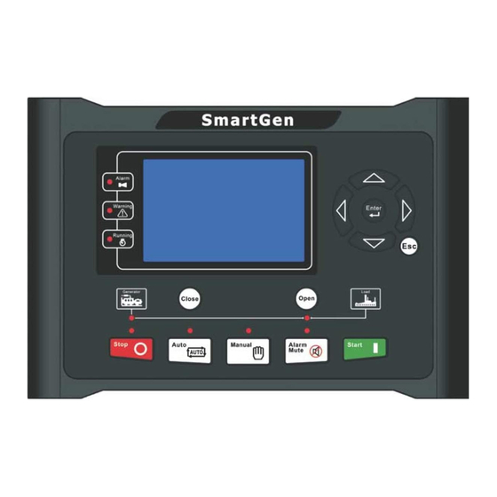
Page 11: Operation
Running indicator: illuminated from crank disconnect to ETS while off during other periods. Generator normal indicator: It is light on when generator is normal; flashing when generator state is abnormal; off when there is no generator power. HGM9510 Genset Parallel Controller User Manual Page 11 of 68... -
Page 12: Key Function Description
HGM9510 Genset Parallel Controller User Manual Page 12 of 68... -
Page 13: Lcd Display
CAUTION: Default password is “00318”, user can change it in case of others change the advanced parameters setting. Please clearly remember the password after changing. If you forget it, please contact SmartGen services and send all information in the controller page of “ABOUT” to us. -
Page 14: User Menu And Parameters Setting Menu
3s to enter into user manual. Parameter After entering the correct password (factory default password is 00318) you can enter parameter settings screen. Language Selectable Chinese, English and others (default: Espanol) Commissioning HGM9510 Genset Parallel Controller User Manual Page 14 of 68... - Page 15 Breaker settings Analog sensor settings Input port settings Output port settings Module settings Scheduling and maintenance settings Synchronization settings Expansion module settings HGM9510 Genset Parallel Controller User Manual Page 15 of 68...
- Page 16 Temp. Sensor > Start Idle Time OP Sensor > Warming Up Time Level Sensor > Cooling Time Config Sensor 1 > Stop Idle Time Config Sensor 2 > ETS Hold Time HGM9510 Genset Parallel Controller User Manual Page 16 of 68...
- Page 17 > Start Idle Time > Warming Up Time > Cooling Time > Stop Idle Time > ETS Hold Time > Wait For Stop NOTE: Pressing can exit setting directly during setting. HGM9510 Genset Parallel Controller User Manual Page 17 of 68...
-
Page 18: Auto Start/Stop Operation
NOTE: When started via “Remote Start (off Load)” input, same procedures as above but generator close relay deactivated, moreover, genset off load. When started via “Remote Start (Demand)” input, the genset will start, synchronize, parallel and share load automatically according to the pre-set priority order. HGM9510 Genset Parallel Controller User Manual Page 18 of 68... -
Page 19: Manual Start/Stop Operation
If bus has no voltage, then the controller will send a closing signal to other waiting parallel gensets and generator close relay will activate, this prevents other sets in the system from attempting to close their own breakers at the same time. HGM9510 Genset Parallel Controller User Manual Page 19 of 68... -
Page 20: Auto Control Procedure
When controller is in auto mode, the switch control procedure is automatic control procedure. NOTE: The auxiliary close input should be configured necessarily and make sure the connection is correct. HGM9510 Genset Parallel Controller User Manual Page 20 of 68... -
Page 21: Protection
If over power detection is enabled, when the controller detects that the Over Power power value (power is positive) has exceeded the pre-set value and the action selects “Warn”, it will initiate a warning alarm. HGM9510 Genset Parallel Controller User Manual Page 21 of 68... - Page 22 If earth fault detection is enabled, when the controller detects that the earth Earth Fault fault current has exceeded the pre-set value and the action select “Warn”, it HGM9510 Genset Parallel Controller User Manual Page 22 of 68...
-
Page 23: Shutdown Alarm
When the controller detects that the genset current has exceeded the Gen Over Current pre-set value and the action selects “Shutdown”, it will initiate a shutdown alarm. HGM9510 Genset Parallel Controller User Manual Page 23 of 68... - Page 24 Flexible Sensor 2 Low pre-set value, it will initiate a shutdown alarm. When digit input port is set as shutdown and the alarm is active, it will Digital Input initiate a shutdown alarm. HGM9510 Genset Parallel Controller User Manual Page 24 of 68...
- Page 25 Controller initiate shutdown alarm after digital input port been configured Detonation Shutdown as detonation shutdown (is active). Controller initiate shutdown alarm after digital input port been configured Gas Leak Shutdown as gas leak shutdown (is active). HGM9510 Genset Parallel Controller User Manual Page 25 of 68...
-
Page 26: Trip And Stop Alarm
When the controller detects that vector shift value has exceeded the Mains Vector Shift pre-set value, it will initiate a trip and stop alarm. HGM9510 Genset Parallel Controller User Manual Page 26 of 68... -
Page 27: Trip Alarm
“Trip”, it will initiate a trip alarm. When the controller detects that the genset negative reactive power has Loss of Excitation exceeded the pre-set value, it will initiate a trip alarm. HGM9510 Genset Parallel Controller User Manual Page 27 of 68... -
Page 28: Wiring Connection
Details table 15. Aux. input 4 1.0mm Ground connected is active (B-) Aux. input 5 1.0mm Ground connected is active (B-) Aux. input 6 1.0mm Ground connected is active (B-) HGM9510 Genset Parallel Controller User Manual Page 28 of 68... - Page 29 Connected to N-wire of gen-set Outside connected to secondary coil of current transformer CT A-phase input 1.5mm (rated 5A) Outside connected to secondary coil of current transformer CT B-phase input 1.5mm (rated 5A) HGM9510 Genset Parallel Controller User Manual Page 29 of 68...
- Page 30 NOTE: USB ports in controller rear panel are configurable parameter ports, user can directly program controller via PC. NOTE: Please refer to the Module Comparison in this manual for more products’ functions. HGM9510 Genset Parallel Controller User Manual Page 30 of 68...
-
Page 31: Scopes And Definitions Of Programmable Parameters
When gas valve closed, it stop to output after Ignition Off Delay (0-60)s the preset delay. Engine Setting Default: Conventional Engine (not J1939) Engine Type (0~39) When connected to J1939 engine, choose the HGM9510 Genset Parallel Controller User Manual Page 31 of 68... - Page 32 Start Attempts (1~10)times reach this number, controller will send start failure signal. See table 17. Crank Disconnect (0~6) There are 3 conditions of disconnecting starter with engine. Each condition can be HGM9510 Genset Parallel Controller User Manual Page 32 of 68...
- Page 33 Setting value is percentage of generator rated (0~200)% Shutdown freq. Delay value (default: 3s) also can be set. Over Volt. Warn (0~200)% 110% Setting value is percentage of generator rated volt. HGM9510 Genset Parallel Controller User Manual Page 33 of 68...
- Page 34 When it is 0, means output constantly. Open Time (0~20.0)s Pulse width of mains/ generator switch off. Module Setting 0: Stop mode 1: Manual mode Power On Mode (0~2) 2: Auto mode HGM9510 Genset Parallel Controller User Manual Page 34 of 68...
- Page 35 0: Disable 1: Enable; (can be set as (0~1) Setting temperature/pressure/liquid lever sensor). Flexible Sensor 2 Flexible Sensor 0: Disable; 1: Enable; (can be set as (0~1) Setting temperature/pressure/liquid lever sensor). HGM9510 Genset Parallel Controller User Manual Page 35 of 68...
- Page 36 Flexible Output Port 1 Contents Setting (0~299) Generator OK. See table 14. Active Type (0~1) 0: Normally open; 1: Normally close Flexible Output Port 2 Contents Setting (0~299) Common Alarm. See table 14. HGM9510 Genset Parallel Controller User Manual Page 36 of 68...
- Page 37 Schedule the load value of other genset when Scheduled Stop PCT (0-100)% start on demand. Load Ramp Rate (0.1-100.0)% Speed rate(%/s) of genset upload/unload Load Ramp Point (0.1-40.0)% 10.0 HGM9510 Genset Parallel Controller User Manual Page 37 of 68...
- Page 38 Load Gain (0-500) Adjust and control after paralleling. Load Stability (0-2000) Adjust and control after paralleling. Sync Setting - AVR Output Type (0-1) 0: Relay output; 1: Analog Voltage Output HGM9510 Genset Parallel Controller User Manual Page 38 of 68...
- Page 39 DMT: overcurrent delay is definite time delay. Different overcurrent value has corresponding delay. IDMT: overcurrent delay decrease with the increase of overcurrent. Different overcurrent value has corresponding delay. IDMT formula: T = t / ((IA/IT)-1) HGM9510 Genset Parallel Controller User Manual Page 39 of 68...
-
Page 40: Enable Definition Of Programmable Output Ports
It is controlled by fuel pump of level sensor’s limited threshold. It is controlled by heating of temperature sensor’s limited Heater Control threshold. Cooler Control It is controlled by cooler of temperature sensor’s limited HGM9510 Genset Parallel Controller User Manual Page 40 of 68... - Page 41 Battery Over Voltage Action when battery over voltage warning alarm occurs. Battery Under Voltage Action when battery low voltage warning alarm occurs. Charge Alternator Failure Action when charge fail warning alarms. Reserved HGM9510 Genset Parallel Controller User Manual Page 41 of 68...
- Page 42 Under Speed Shutdown Action when under speed shuts down occurs. Over Speed Warn Action when over speed warn occurs. Over Speed Shutdown Action when over speed shutdown alarm occurs. Reserved HGM9510 Genset Parallel Controller User Manual Page 42 of 68...
- Page 43 Flexible Sensor 1 High Shut Flexible Sensor 1 Low Shut Flexible Sensor High Warn Flexible Sensor 2 Low Warn Flexible Sensor 2 High Shut Flexible Sensor 2 Low Shut 158-229 Reserved HGM9510 Genset Parallel Controller User Manual Page 43 of 68...
-
Page 44: Defined Period Output
Contents of OR condition output S1: output port 1 is active; Close when OR condition output S1 is active /inactive: close when active (disconnect when inactive); Contents of OR condition output S2, output port 2 is active; HGM9510 Genset Parallel Controller User Manual Page 44 of 68... -
Page 45: Defined Contents Of Programmable Input Ports (All Gnd(B-) Connected Active)
In Auto mode, prohibit scheduled start genset when input is Inhibit Scheduled active. Reserved Aux Gen Closed Connect generator loading switch’s Aux. Point. Inhibit Gen Load Prohibit genset switch on when input is active. Reserved HGM9510 Genset Parallel Controller User Manual Page 45 of 68... - Page 46 Simulate Auto key An external button (not self-lock) can be connected and pressed as simulate panel. Simulate Start key This is simulate G-close key when HGM9510 controller is Simulate G-Load key applied. This is simulate G-open key when HGM9510 controller is Simulate M-Load key applied.
- Page 47 Low Coolant Level Connect with water level sensor digital input port. Detonation Shutdown Connect with detection module warn input port. Gas Leak Shutdown Connect with detection module warn input port. Reserved Reserved HGM9510 Genset Parallel Controller User Manual Page 47 of 68...
-
Page 48: Selection Of Sensors
Fuel Level Sensor 3 SGD 0~6KΩ, default is SGH sensor. 4 SGH 5~15 Reserved NOTE: User should make special declare when order controller if your genset equipped with sensor of 4~20mA. HGM9510 Genset Parallel Controller User Manual Page 48 of 68... -
Page 49: Conditions Of Crank Disconnect Selection
NOTE: Configurable input could not be set as same items; otherwise, there are abnormal functions. However, the configurable output can be set as same items. HGM9510 Genset Parallel Controller User Manual Page 49 of 68... -
Page 50: Sensors Setting
Fig. 3 Sensor Curve Table 18 Normal Pressure Unit Conversion Form (Pa) kgf/cm - - - 1.02x10 1x10 1.45x10 1kgf/cm 9.8x10 0.98 14.2 1bar 1x10 1.02 14.5 - - 1psi 6.89x10 7.03x10 6.89x10 HGM9510 Genset Parallel Controller User Manual Page 50 of 68... -
Page 51: Commissioning
During parallel operation off load, check if the output of active and reactive power is equal to zero; if it is not, then check if there is power oscillation; if there is, adjust the gain and stability values of HGM9510 controller, or adjust engine GOV or generator AVR gain and stability potentiometer to avoid active and reactive power oscillation;... - Page 52 (both “start on demand” or “start all sets initially” modes are possible); other gen-sets enter parallel operation after synchronizing. Opening breaker, unloading and stop is performed automatically. All the gen-sets are repeatedly started and stopped according to their total run time. HGM9510 Genset Parallel Controller User Manual Page 52 of 68...
-
Page 53: Typical Application
12 TYPICAL APPLICATION Fig. 4 HGM9510 Typical Application Diagram NOTE: Fuse F1: min. 2A; max. 20A. Fuse F2: max. 32A. Users should select suitable fuse depend on practical application. Fig. 5 3 Phase 3 Wire Application Diagram Fig. 6 2 Phase 3 Wire Application Diagram... - Page 54 Fig. 8 HGM9510 Multi-genset Parallel Application Diagram NOTE: Mains parallel function for HGM9510 controller can be selected via configurable input port. In mains parallel mode, generator will run in parallel with mains and it will only be able to output a fixed amount of power. (Set load mode as Gen control mode).
-
Page 55: Power Management Mode
13 POWER MANAGEMENT MODE Power management mode can be selected via configurable input ports. Fig. 9 Power Management Logic HGM9510 Genset Parallel Controller User Manual Page 55 of 68... -
Page 56: Nel Trip
NEL reconnection value, then the input is active; if it doesn’t, the input is deactivated. NOTE: When auto trip and auto reconnection are enabled, manual trip is still active. HGM9510 Genset Parallel Controller User Manual Page 56 of 68... -
Page 57: Installation
Fig. 11 Overall Dimensions and Panel Cutout Battery Voltage Input NOTE: HGM9510 controller can suit for widely range of battery voltage (8~35) VDC. Negative of battery must be connected with the shell of starter stable. The wire’s diameter must be over 2.5mm and which is connected to B+ and B- of controller power. - Page 58 CAUTION: When controller had been installed in control panel, if need the high voltage test, please disconnect controller’s all terminal connections, in order to prevent high voltage into controller and damage it. HGM9510 Genset Parallel Controller User Manual Page 58 of 68...
-
Page 59: Connections Of Controller With J1939 Engine
C1 connector Remark Outside expand relay, when fuel output, Fuel relay output 5&8 making port 5 and port 8 of C1 be connected. Starting relay output Connect to starter coil directly. HGM9510 Genset Parallel Controller User Manual Page 59 of 68... -
Page 60: Cummins Qsx15-Cm570
CAN communication shielding line (connect RS485 GND with ECU terminal only). RS485+ Using impedance 120Ω connecting line. RS485- Using impedance 120Ω connecting line. Engine type: Cummins QSK-MODBUS, Cummins QST-MODBUS, Cummins QSX-MODBUS. HGM9510 Genset Parallel Controller User Manual Page 60 of 68... -
Page 61: Cummins Qsm11
CAN communication shielding line (connect CAN GND with controller’s this terminal only). CAN(H) Using impedance 120Ω connecting line. CAN(L) Using impedance 120Ω connecting line. Engine type: Common J1939. HGM9510 Genset Parallel Controller User Manual Page 61 of 68... -
Page 62: Detroit Diesel Ddec Iii/Iv
Starting relay output CAN communication shielding line (connect CAN GND with controller’s terminal only). CAN(H) Using impedance 120Ω connecting line CAN(L) Using impedance 120Ω connecting line Engine type: John Deere. HGM9510 Genset Parallel Controller User Manual Page 62 of 68... -
Page 63: Mtu Mdec
ADEC (X1 port) Remark X1 Terminal 28 Connected to negative of Fuel relay output X1 43 battery. X1 Terminal 22 Connected to negative of Starting relay output X1 37 battery. HGM9510 Genset Parallel Controller User Manual Page 63 of 68... -
Page 64: Perkins
Table 41 “Stand alone” Connector Terminals of controller “Stand alone” connector Remark Fuel relay output Starting relay output ECU power; Programmable output 1 Set programmable output 1 as “ECU power”. HGM9510 Genset Parallel Controller User Manual Page 64 of 68... -
Page 65: Volvo Edc4
Using impedance 120Ω connecting line. CAN(L) 2(Lo) Using impedance 120Ω connecting line. Engine type: Volvo-EMS2. NOTE: When this engine type is selected, preheating time should be set to at least 3 seconds. HGM9510 Genset Parallel Controller User Manual Page 65 of 68... -
Page 66: Yuchai
CAN(L) 1.34 Using impedance 120Ω connecting line. Engine type: GTSC1. NOTE: If there is any question of connection between controller and ECU communication, please feel free to contact Smartgen’s service. HGM9510 Genset Parallel Controller User Manual Page 66 of 68... -
Page 67: Usb
Users can set the controller’s parameters and monitor the controller’s status via the test software which provided by Smatgen company. The connection way between PC and controller as following: Fig.12 USB Connection Method HGM9510 Genset Parallel Controller User Manual Page 67 of 68... -
Page 68: Fault Finding
Get information from LCD of alarm page; ECU warning or stop If there is detailed alarm, check engine according to description. If not, please refer to engine manual according to SPN alarm code. _____________________________________ HGM9510 Genset Parallel Controller User Manual Page 68 of 68...
Need help?
Do you have a question about the HGM9510 and is the answer not in the manual?
Questions and answers