
Subscribe to Our Youtube Channel
Related Manuals for Smartgen HGM7220N Series


Summary of Contents for Smartgen HGM7220N Series
- Page 1 HGM7220N/HGM7220S SERIES GENSET CONTROLLER USER MANUAL SMARTGEN (ZHENGZHOU) TECHNOLOGY CO., LTD.
- Page 2 SmartGen Technology at the address above. Any reference to trademarked product names used within this publication is owned by their respective companies. SmartGen Technology reserves the right to change the contents of this document without prior notice. Table 1 - Software Version Date...
-
Page 3: Table Of Contents
HGM7220N/HGM7220S GENSET CONTROLLER USER MANUAL CONTENTS 1 OVERVIEW .............................. 5 2 PERFORMANCE AND CHARACTERISTICS ..................6 3 SPECIFICATION OPERATION ....................... 8 4 OPERATION ............................9 4.1 KEY FUNCTION ..........................9 4.2 CONTROLLER PANEL ........................ 10 4.3 AUTO START/STOP OPERATION ....................11 4.3.1. - Page 4 HGM7220N/HGM7220S GENSET CONTROLLER USER MANUAL 12 COMMISSIONING ..........................45 13 TYPICAL APPLICATION ........................46 14 INSTALLATION ............................. 47 14.1 SGE02 EXPANSION MODULE ....................47 14.2 FIXING CLIPS ..........................48 14.3 OVERALL DIMENSION ....................... 49 15 SMS MESSAGE ALARM AND REMOTE CONTROL ................50 16.1 SMS MESSAGE ALARM ......................
-
Page 5: Overview
HGM7220N/HGM7220S GENSET CONTROLLER USER MANUAL OVERVIEW HGM7220N/HGM7220S series genset controller is used for single unit automation control, which can realize functions of single unit self-start, AMF, synchronization changeover, and cloud monitoring. It integrates digitalization, intelligence, with network technology. It applies LCD graph display, optional language interface (Chinese, English and etc.) with reliable and simple operating features. -
Page 6: Performance And Characteristics
HGM7220N/HGM7220S GENSET CONTROLLER USER MANUAL PERFORMANCE AND CHARACTERISTICS HGM7220N: has mains&generating power monitoring function, which are used for mains/generating automatic changeover control. It is applicable for single unit automation system consisting of one mains circuit and one generating circuit. Mains disable can be performed by parameter setting and at this time it is used for single unit automation and genset self-start and self-stop can be controlled by remote start signal. - Page 7 HGM7220N/HGM7220S GENSET CONTROLLER USER MANUAL with perfect fault indication and protection functions. — ETS (energize to stop), idling speed control, pre-heating control and speed rise/drop control functions and all of them are relay outputs. — Parameter setting function: parameters can be modified and set by users and they won’t get lost in case of power outage.
-
Page 8: Specification Operation
HGM7220N/HGM7220S GENSET CONTROLLER USER MANUAL SPECIFICATION OPERATION Table 2 - Technical Parameters Items Contents Working Voltage DC8.0V to DC35.0V Continuous <4W (standby ≤2W) Whole Power Consumption Alternator Volt Input: 3Phase 4Wire 15V AC - 360 V AC (ph-N) 3Phase 3Wire 30V AC - 620 V AC (ph-ph) Single Phase 2Wire 15V AC - 360 V AC (ph-N) -
Page 9: Operation
HGM7220N/HGM7220S GENSET CONTROLLER USER MANUAL OPERATION KEY FUNCTION Table 3 - Key Function Descriptions Icon Function Description Stop the running genset both in Auto/Manual mode; Remove the alarm in stop mode; Stop/ Reset Press for 3 seconds or over and panel indicators can be tested (lamp test);... -
Page 10: Controller Panel
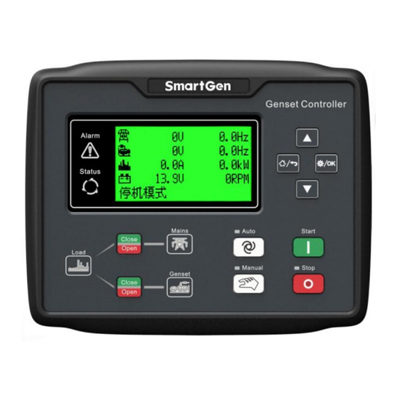
HGM7220N/HGM7220S GENSET CONTROLLER USER MANUAL CONTROLLER PANEL Figure 1 - HGM7220N/7220S Front Panel Indication NOTE: Illustration for part indicators. Table 4 - Alarm Indicator Description Alarm Type Alarm Indicators Warning alarm slowly flashing (once per second) Trip alarm slowly flashing (once per second) Shutdown alarm fast flashing (5 times per second) Trip and stop alarm... -
Page 11: Auto Start/Stop Operation
HGM7220N/HGM7220S GENSET CONTROLLER USER MANUAL AUTO START/STOP OPERATION 4.3.1. ILLUSTRATION Press and the indicator beside is illuminated, meaning genset is in Auto Start mode. 4.3.2. AUTO START SEQUENCE HGM7220N/HGM7220S Start Conditions: Mains Enable: When mains is abnormal (over and under voltage, over and under frequency, loss of phase and inverse phase), genset enters “mains abnormal delay”... -
Page 12: Manual Start/Stop Operation
HGM7220N/HGM7220S GENSET CONTROLLER USER MANUAL HGM7220N: starts “cooling delay”, meanwhile generating close relay is disconnected. After “transfer ① reset delay”, mains close relay outputs, mains is on-load, gens power supply indicator is light off,m and mains supply indicator is light on. ②... -
Page 13: Auto Switching Process
HGM7220N/HGM7220S GENSET CONTROLLER USER MANUAL Operator controls load transfer of ATS via pressing button. Mains Enable: When breaker open detection is disabled, (1) press generator button, open breaker will output if generator is on-load; generator will be closed if load is disconnected; mains will be opened if mains is on-load, and generator is closed after open delay is over;... -
Page 14: Hgm7220S Breaker Control Process
HGM7220N/HGM7220S GENSET CONTROLLER USER MANUAL failure shall issue warning signal. In case input port is not configured as close status auxiliary input, Mains Enable: For mains on-load changing to generator on-load, after open delay and transfer rest delay, generator close occurs. For generator on-load changing to mains on-load, it is the same as above. Mains Disable: For generator off-load changing to generator on-load, generator close outputs. - Page 15 HGM7220N/HGM7220S GENSET CONTROLLER USER MANUAL due, if generator close fails generator close is waited for. If input port not configured as close status auxiliary input Controller shall output mains close when genset and generator meet synchronization conditions. When it detects mains close feedback signal, generator open outputs and mains is on-load. If mains close is outputted, mains close feedback signal is not detected during the C/O synchronization period, mains open is outputted and generator is on-load.
-
Page 16: Protection
HGM7220N/HGM7220S GENSET CONTROLLER USER MANUAL PROTECTION WARNINGS When controller detects the warning alarms, it only issues alarm and does not stop the genset. Table 5 - Warning Alarm Types Type Description When the controller detects that the genset speed exceeds the pre-set Gen. - Page 17 HGM7220N/HGM7220S GENSET CONTROLLER USER MANUAL Type Description When controller detects that the phase sequence of generator is Gen. Reverse Phase wrong, it will initiate a warning alarm. HGM7220S controller: When controller is in auto mode, if synchronization signal is not detected during the synchronization time Fail to Sych Warn for mains synchronization close and generator synchronization close, it shall issue a warning signal.
-
Page 18: Shutdown Alarm
HGM7220N/HGM7220S GENSET CONTROLLER USER MANUAL SHUTDOWN ALARM When controller detects shutdown alarms, it will send signals to stop the generator and the corresponding alarm information will be displayed on LCD. Table 6 - Shutdown Alarms Type Description When controller detects emergency stop signals, it will send stop Emergency Stop signals. -
Page 19: Trip And Stop Alarm
HGM7220N/HGM7220S GENSET CONTROLLER USER MANUAL Type Description Low Oil Pressure When controller detects oil pressure is lower than the set value, it will Shutdown send stop signals. Level Sensor Open When controller detects sensor is open circuit, and the action is selected “Shutdown”, it will send stop signals. -
Page 20: Trip Alarm
HGM7220N/HGM7220S GENSET CONTROLLER USER MANUAL TRIP ALARM When controller detects trip alarms, it will immediately disconnect the generator close signals but genset does not stop. Table 8 - Trip Alarms Type Description When controller detects the genset current value is higher than the set Over Current value and action is selected “Trip”, it will send trip signals. -
Page 21: Wirings Connection
HGM7220N/HGM7220S GENSET CONTROLLER USER MANUAL WIRINGS CONNECTION HGM7220N/7220S controller back panel is as below. Figure 2 - Back Panel HGM7220N/HGM7220S Genset Controller 2019-02-28 Version 1.0 Page 21 of 60... - Page 22 HGM7220N/HGM7220S GENSET CONTROLLER USER MANUAL Table 9 - Terminal Wiring Connection Function Cable Size Remarks 2.5mm Connected with negative of starter battery. Connected with positive of starter battery. If wire length 2.5mm is over 30m, it’s better to double wires in parallel. Max. 20A fuse is recommended.
- Page 23 HGM7220N/HGM7220S GENSET CONTROLLER USER MANUAL Function Cable Size Remarks Configurable Sensor 1 Connected with temp/pressure/fuel level For items please see sensor. Table 13. Configurable Sensor 2 CT A-phase Monitoring Input 1.5mm Outside connected to secondary coil of CT (5A rated). CT B-phase Monitoring Input 1.5mm Outside connected to secondary coil of CT (5A rated).
-
Page 24: Scopes And Definitions Of Programmable Parameters
HGM7220N/HGM7220S GENSET CONTROLLER USER MANUAL SCOPES AND DEFINITIONS OF PROGRAMMABLE PARAMETERS CONTENTS AND SCOPES OF PARAMETERS Table 10 - Parameter Settings and Scope Items Range Default Description Mains Setting (0-1) Mains Enable 0: Disable; 1: Enable 0: 3P4W; 1: 3P3W (0-3) AC System 2: 2P3W... - Page 25 HGM7220N/HGM7220S GENSET CONTROLLER USER MANUAL Items Range Default Description Cooling time before genset stop after genset Cooling Time (0-3600)s deloading. Running time for idling speed when genset 10 Stop Idle Time (0-3600)s stops. Time for ETS energization before genset ETS Hold Time (0-3600)s stop.
- Page 26 HGM7220N/HGM7220S GENSET CONTROLLER USER MANUAL Items Range Default Description Maximum crank times when engine start 15 Start Attempts (1-10)times fails. If it reaches this number, controller will send start failure signals. For details please see table 14. There are 3 cranking disconnect conditions, Crank Disconnect (0-6) which can be used separately or together,...
- Page 27 HGM7220N/HGM7220S GENSET CONTROLLER USER MANUAL Items Range Default Description The set value is rated voltage percentage. The controller detects it while gen-set Voltage On-load (0-200)% prepares to take the load, if voltage is less than the on-load voltage, gen-set will not enter normal operation period.
- Page 28 HGM7220N/HGM7220S GENSET CONTROLLER USER MANUAL Items Range Default Description Reverse Power (0-1) 0: Disabled; 1: Enabled Setting Load Setting (5-6000)/5 Current Transform Changes of Externally connected CT. Generator rated current, standard for load (5-6000)A Rated Current current. Generator rated power, standard for load (0-6000)kW Rated Power power.
- Page 29 HGM7220N/HGM7220S GENSET CONTROLLER USER MANUAL Items Range Default Description The max. waiting sync. time; if time is due and still meets 15 Fail Sync Delay (0-3600)s the sync. conditions, then sync. failure alarm is issued. During sync. changeover, sync. close or open output delay starts, during the delay if correct close/open status is detected,...
- Page 30 HGM7220N/HGM7220S GENSET CONTROLLER USER MANUAL Items Range Default Description When externally connected temperature sensor value is higher than the set point, High Temp controller will initiate high temperature (-50-300)º C warning alarm. It is only judged after “safety Warning on delay” is over. Return value and delay value can be set.
- Page 31 HGM7220N/HGM7220S GENSET CONTROLLER USER MANUAL Items Range Default Description Active Type (0-1) 0: Close; 1: Open Digital Input 2 High temperature shutdown input. For Content Setting (0-50) details please see table 12. (0-1) Active Type 0: Close; 1: Open Digital Input 3 Low oil pressure shutdown input.
- Page 32 HGM7220N/HGM7220S GENSET CONTROLLER USER MANUAL Items Range Default Description LCD displays corresponding content when Description input port is active. Digital Input 7 User defined. For details please see table Content Setting (0-50) (0-1) Active Type 0: Close; 1: Open 0: From safety on delay; 1: From crank; 2: (0-3) Active Range Always;...
-
Page 33: Definition Content Of Programmable Output Ports 1~6
HGM7220N/HGM7220S GENSET CONTROLLER USER MANUAL Items Range Default Description SGE02-4G Setting SGE02-4G Enable (0-1) 0: Disabled; 1: Enabled SMS Enable (0-1) 0: Disabled; 1: Enabled All numbers are needed to add district or country Mobile Number Max. 20 bits number, e.g. China 13666666666. GPRS Enable (0-1) 0: Disabled;... - Page 34 HGM7220N/HGM7220S GENSET CONTROLLER USER MANUAL Type Description active, audible alarm can be inhibited. It is activated from starting generator and disconnected after Louver Control generator’s complete stop. It is controlled by the upper/lower limits of the sensor fuel Fuel Pump Control pump.
- Page 35 HGM7220N/HGM7220S GENSET CONTROLLER USER MANUAL Type Description Common Ele Trip Activated when common electrical trip and stop occurs. Common Shutdown Activated when common shutdown occurs. Common Trip Alarm Activated when common trip alarms occur. Common Warn Alarm Activated when common warnings occur. Reserved Battery High Voltage Activated when battery voltage is over too high.
- Page 36 HGM7220N/HGM7220S GENSET CONTROLLER USER MANUAL Type Description Activated when generator over frequency shutdown alarm Gen. Over Freq Shutdown occurs. Gen. Over Voltage Warning Activated when generator over voltage warning alarm occurs. Activated when generator over voltage shutdown alarm Gen. Over Volt Shutdown occurs.
-
Page 37: Custom Period Output
HGM7220N/HGM7220S GENSET CONTROLLER USER MANUAL Type Description Reserved Config. Sensor 1 High Warning Config. Sensor 1 Low Warning Config. Sensor 1 High Shutdown Config.Sensor 1 Low Shutdown Config. Sensor 2 High Warning Config. Sensor 2 Low Warning Config. Sensor 2 High Shutdown Config. -
Page 38: Custom Combined Output
HGM7220N/HGM7220S GENSET CONTROLLER USER MANUAL 8.2.2. CUSTOM COMBINED OUTPUT Defined combination output is composed by 3 parts, condition output S1 or S2 and condition output S1 or S2 is TRUE, while S3 is TRUE, defined combination output is outputting; S1 and S2 are FALSE, or S3 is FALSE, defined combination output is not outputting. NOTE: S1, S2, S3 can be set as any contents except for “defined combination output”... - Page 39 HGM7220N/HGM7220S GENSET CONTROLLER USER MANUAL Items Description When input is active, all LED indicators are light. Lamp Test When input is active, all buttons on the panel are inactive except Panel Lock , and displays on the right side of the first line of LCD status page.
- Page 40 HGM7220N/HGM7220S GENSET CONTROLLER USER MANUAL Items Description is inactive, gen-set will be stopped automatically. When input is active in manual mode, gen-set will be started Aux Manual Start automatically. When input is inactive, gen-set will be stopped automatically. Simulate Up Key Externally connecting a button to simulate key function on the panel.
-
Page 41: Selection Of Sensors
HGM7220N/HGM7220S GENSET CONTROLLER USER MANUAL SELECTION OF SENSORS Table 13 - Sensors Selection Description Remark 0 Not used 1 Custom resistor type curve 2 Custom current/voltage curve 3 VDO 4 CURTIS resistance’s Defined 5 VOLVO-EC range is 0~6KΩ, default Temperature Sensor 6 DATCON 7 SGX is SGX sensor. -
Page 42: Conditions Of Crank Disconnect Selection
HGM7220N/HGM7220S GENSET CONTROLLER USER MANUAL CONDITIONS OF CRANK DISCONNECT SELECTION Table 14 - Crank Disconnect Conditions Selection Setting description Gen frequency Speed Speed + Gen frequency Oil pressure Oil pressure + Gen frequency Speed + Oil pressure Speed + Gen frequency + Oil pressure NOTES: There are 3 conditions to make starter separate with engine;... -
Page 43: Language Selection
HGM7220N/HGM7220S GENSET CONTROLLER USER MANUAL NOTES: a) Please change the controller parameters when generator is in standby mode (e. g. Crank disconnect conditions selection, digital inputs, relay outputs, various delays), otherwise, shutdown and other abnormal conditions may occur. b) Upper limit value must be higher than lower limit value, for example, over voltage limit muse be higher than under voltage limit, otherwise over voltage and under voltage conditions may occur simultaneously. -
Page 44: Sensor Setting
HGM7220N/HGM7220S GENSET CONTROLLER USER MANUAL only active in auto mode. Operational Process: When remote start input is active, the main set is in standby status, it will start automatically, and the running time is the pre-configured “Main Set Running Time”; If “Main Set Running Time”... -
Page 45: Commissioning
ATS transfer into generator load. If it is not like this, please check ATS’ wiring connection according to this manual. — If there is any other question, please contact SmartGen’s service. HGM7220N/HGM7220S Genset Controller 2019-02-28 Version 1.0... -
Page 46: Typical Application
HGM7220N/HGM7220S GENSET CONTROLLER USER MANUAL 13 TYPICAL APPLICATION Figure 4 - HGM7220S Typical Application Figure 5 - HGM7220N Typical Application HGM7220N/HGM7220S Genset Controller 2019-02-28 Version 1.0 Page 46 of 60... -
Page 47: Installation
HGM7220N/HGM7220S GENSET CONTROLLER USER MANUAL Figure 6 - Single Phase 2-Wire Connection Diagram Figure 7 – 2-Phase 3-Wire Connection Diagram NOTE: Expand relay with high capacity in start and fuel output is recommend. 14 INSTALLATION 14.1 SGE02 EXPANSION MODULE 14.1.1 4G ANTENNA PORT Connect 4G antenna and 4G port of SGE02. -
Page 48: Fixing Clips
HGM7220N/HGM7220S GENSET CONTROLLER USER MANUAL Figure 8 - HGM7220N/7220S Antenna Connection 14.1.3 SIM CARD INSTALLATION Insert 4G, 3G or 2G SIM card, and connect it with servicer via wireless network. NOTE: This module supports 4G wireless network fitting all networks. Standard SIM card (size: 25mmx15mm) is applied. -
Page 49: Overall Dimension
HGM7220N/HGM7220S GENSET CONTROLLER USER MANUAL 14.3 OVERALL DIMENSION Figure 10 - Overall Dimensions HGM7220N7220S series controller can suit for wide range of battery voltage DC (8~35) V. Negative of battery must be connected with the engine shell. Diameter of wire that connects power supply with battery must be over 2.5mm . -
Page 50: Sms Message Alarm And Remote Control
HGM7220N/HGM7220S GENSET CONTROLLER USER MANUAL 15 SMS MESSAGE ALARM AND REMOTE CONTROL 16.1 SMS MESSAGE ALARM When controller detects alarms, it shall sends messages automatically to the set mobile number. NOTE: All stop alarms, trip and stop alarms, trip alarms will send messages to the pre-set phone number and optional alarms will send messages to the phone according to user settings. -
Page 51: Connections Of Controller And J1939 Engine
HGM7220N/HGM7220S GENSET CONTROLLER USER MANUAL NOTE: Detailed contents for SMS DETAIL return include: operating mode, mains voltage, gens voltage, load current, mains frequency, gens frequency, active power, apparent power, power factor, battery voltage, D+ voltage, water temperature, oil pressure, fuel level, speed, accumulated running time, genset status, alarm status. 16 CONNECTIONS OF CONTROLLER AND J1939 ENGINE 16.1 CUMMINS ISB/ISBE Table 17 Connector B... -
Page 52: Cummins Qsx15-Cm570
HGM7220N/HGM7220S GENSET CONTROLLER USER MANUAL Table 21 C1 Connector Terminals of controller C1 connector Remark Set it as “fuel output”; External expansion Aux. output port 1 5&8 relay; on fuel output, make port 5 and port 8 of C1 connector be connected; Start relay output Connected to starter coil directly;... -
Page 53: Cummins Qsm11
HGM7220N/HGM7220S GENSET CONTROLLER USER MANUAL Table 26 D-SUB Connector 06 Terminals of controller D-SUB connector 06 Remark CAN communication shielding RS485 GND line(connected with terminal only); Using impedance 120Ω RS485+ connecting line; Using impedance 120Ω RS485- connecting line; Engine type: Cummins QSK-MODBUS, Cummins QST-MODBUS, Cummins QSX-MODBUS. 16.6 CUMMINS QSM11 Table 27 Engine OEM Connector Terminals of controller... -
Page 54: Deutz Emr2
HGM7220N/HGM7220S GENSET CONTROLLER USER MANUAL Table 29 Engine CAN Port Terminals of controller CAN port of engine Remark Set it as “fuel output”; Expansion relay, Aux. output port 1 proving battery voltage for ECU; Start relay output Connected to starter coil directly; CAN_SCR CAN communication shielding line;... -
Page 55: Mtu Mdec
HGM7220N/HGM7220S GENSET CONTROLLER USER MANUAL 16.11 MTU MDEC Suitable for 2000 series and 4000 series with MTU engine type. Table 32 X1 Connector Terminals of controller X1 Connector Remark Set it as “fuel output”; Aux. output port 1 Start relay output CAN communication shielding line(connected CAN_SCR with one terminal only);... -
Page 56: Perkins
HGM7220N/HGM7220S GENSET CONTROLLER USER MANUAL 16.14 PERKINS It is suitable for ADEM3/ ADEM4 engine control module. Engine type is 2306, 2506, 1106, and 2806. Table 37 Connector Terminals of controller Connector Remark Set it as “fuel output”; Aux. output port 1 1,10,15,33,34 Start relay output Connected to starter coil directly;... -
Page 57: Volvo-Ems2
HGM7220N/HGM7220S GENSET CONTROLLER USER MANUAL Table 41 Connector Terminals of controller Connector Remark Set it as “fuel output”; Expansion relay, Aux. output port 1 providing battery voltage for terminal 14. Fuse is 16A. Start relay output Connected to starter coil directly; Connected to negative of battery;... -
Page 58: Weichai
Using impedance 120Ω connecting line; CAN(L) 1.34 Engine type: GTSC1. NOTE: If there is any question of connection between controller and ECU communication, please feel free to contact SmartGen’s service. HGM7220N/HGM7220S Genset Controller 2019-02-28 Version 1.0 Page 58 of 60... -
Page 59: Troubleshooting
HGM7220N/HGM7220S GENSET CONTROLLER USER MANUAL 17 TROUBLESHOOTING Table 46 - Troubleshooting Symptoms Possible Solutions Check starting batteries; Controller no response with power. Check controller connection wirings; Check DC fuse. Check the water/cylinder temperature is too high or not; Gen-set shutdown Check the gen-set AC voltage;... -
Page 60: Appendix
HGM7220N/HGM7220S GENSET CONTROLLER USER MANUAL 18 Appendix Table 47 SGE02-4G Order Model Model Country Frequency Channel Remark SGE02-4G Chinese Mainland FDD-LTE: B1/B3/B8 TDD-LTE: B38/B39/B40/B41 TD-SCDMA: B34/B39 SIM7600CE WCDMA: B1/B8 EVDO/CDMA: BC0 GSM: 900/1800MHz FDD-LTE: B2/B4/B12 SGE02-4G-S01 SIM7600A-H North America WCDMA: B2/B5 SGE02-4G-S02 FDD-LTE: B2/B4/B5/B13 SIM7600V-H...
Need help?
Do you have a question about the HGM7220N Series and is the answer not in the manual?
Questions and answers