Table of Contents
Advertisement
Quick Links
Advertisement
Table of Contents
Troubleshooting

Related Manuals for Oce Arizona 365 GT


Summary of Contents for Oce Arizona 365 GT
- Page 1 Operation guide Océ Arizona 365 GT User Manual...
- Page 2 Copyright Copyright Copyright 2018, 2019 Océ. Illustrations and specifications do not necessarily apply to products and services offered in each local market. No part of this publication may be reproduced, copied, adapted or transmitted, transcribed, stored in a retrieval system, or translated into any language or computer language in any form or by any means, electronic, mechanical, optical, chemical, manual, or otherwise, without the prior written permission of Océ.
-
Page 3: Table Of Contents
Contents Contents Chapter 1 Introduction.........................7 Preface................................8 Product Compliance............................9 Chapter 2 Product Overview......................11 Printer Specifications............................. 12 Chapter 3 Safety Information......................13 Safety and Environment Information......................14 Flush................................24 UV Curing System ............................25 Safety Interlock System..........................26 Safety Awareness............................27 Roll Media Safety Awareness........................36 Chapter 4 How to Navigate the User Interface................ - Page 4 Contents Roll Media Option Hardware......................... 78 Roll Media Option Specifications........................80 Foot Pedal Switch Functions......................... 82 Roll Media Manager............................83 How to Load Media............................85 Load an Empty Core and Install in the Take-up Position..............87 Loading the Media - Standard Method....................89 Loading the Media - Alternate Method ....................
- Page 5 Contents Chapter 10 Error Handling and Troubleshooting................171 Troubleshooting Overview.......................... 172 Chapter 11 Printer Maintenance....................... 175 Maintenance Guidelines..........................176 Maintenance Procedures..........................178 Clean Carriage Underside........................178 Printhead Maintenance..........................180 How to Print and Evaluate a Nozzle Check..................183 Printhead Maintenance - Maintenance for Select Printheads............185 Swab Printheads............................
- Page 6 Contents...
-
Page 7: Chapter 1 Introduction
Chapter 1 Introduction... -
Page 8: Preface
This manual provides the operator with information about the Océ Arizona® 365 GT UV flatbed inkjet printers. This manual uses the term Océ Arizona 365 GT to refer to the printers. The manual orients you to the many features and procedures that allow you to print professional quality images on various media with the printer. -
Page 9: Product Compliance
Product Compliance Product Compliance CE Declaration of Conformity ___________________________________ Chapter 1 - Introduction... - Page 10 Product Compliance Marking Declaration Table China Pollution Act Toxic and Hazardous Substances or Elements in the Product Part Name Lead (Pb) Mercury Cadmium Hexavalent Polybromi‐ Polybromi‐ (Hg) (Cd) (CrVI) ated bi‐ nated dipe‐ phenyls nylether (PBB) (PBDE) Curing Lamp Inkjet Heads O: indicates that the content of the toxic and hazardous substance in all the homogeneous materials of the part is below the concentration limit requirement as described in GB/T26572.
-
Page 11: Chapter 2 Product Overview
Chapter 2 Product Overview... -
Page 12: Printer Specifications
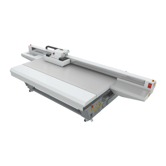
Printer Specifications Introduction The Océ Arizona 365 GT is a flatbed inkjet printer capable of producing large format images on various rigid and flexible media. The printers consist of a flatbed vacuum table and moving gantry. Media is held flat and stationary on the vacuum table during printing. The gantry contains a carriage that sweeps across the table as the gantry moves in steps along the length of the table to print an image on the media. -
Page 13: Chapter 3 Safety Information
Chapter 3 Safety Information... -
Page 14: Safety And Environment Information
Disclaimer: OCE MAKES NO WARRANTY OF ANY KIND WITH REGARD TO THE CONTENT OF THIS DOCUMENTATION AND ITS COMPLETENESS, EITHER EXPRESS OR IMPLIED, EXCEPT AS PROVIDED HEREIN, INCLUDING WITHOUT LIMITATION, THEREOF, WARRANTIES AS TO MARKETABILITY, MERCHANTABILITY AND FITNESS FOR A PARTICULAR PURPOSE OF USE OR NON-INFRINGEMENT. - Page 15 Safety and Environment Information The following indicators are used in the User Documentation to identify and categorize the level of the seriousness of hazard: Symbol Type Description WARNING Indicates a warning concerning operations that may lead to injury or even death to persons if not performed correctly. To use the machine safely, always pay attention to these warn- ings.
- Page 16 Safety and Environment Information Label Type Description CAUTION Crushing of hands. WARNING Shock hazard. Disconnect all power sources before servicing. For authorized service personnel only. WARNING High touch current. Risk of electrical shock Connect to earth before connecting the power supply. Refer to installation instructions, before operating the equip- ment.
- Page 17 Safety and Environment Information Label Type Description CAUTION Warning: Optical radiation. Read the user documentation before you perform this task or action. Translation: Avoid looking directly at lamps. Optical radi- ation according EN 12198 Category 2. Special restric- tions and protective measures are essential when the machine is used in the workplace.
- Page 18 Safety and Environment Information Power cord WARNING • Do not scratch, abrade, heat, twist, bend, or place a heavy object on the power cord or cause any other damage to it. The use of a damaged power cord (e.g. exposed core wire or broken wire) could result in an electrical shock, fire or malfunction of the machine.
- Page 19 Safety and Environment Information Installation WARNING • The machine may only be transported, assembled, installed and repaired by an authorized service representative. • The installation of accessories and options not permitted for the machines may constitute a violation of the Safety Regulations and Directives, and may also damage the machine. •...
- Page 20 Safety and Environment Information CAUTION • This equipment is not suitable for use in locations where children are likely to be present. • The printing system may not be operated by persons under the influence of alcohol or drugs, or by persons taking certain types of medication, such as psychotropic drugs. Disassemble and modification WARNING •...
- Page 21 Safety and Environment Information Actions in response to troubles WARNING • Immediately turn OFF the power switch and unplug the power cord from the power outlet when a piece of metal, water or any other similar foreign matter gets inside the machine. Then call your authorized service representative.
- Page 22 Safety and Environment Information UV ink CAUTION • UV inks and flush liquids can be harmful if not properly handled. Follow always the Safety Data Sheets (SDS) guidelines carefully in order to ensure maximum safety. • Avoid skin contact with ink and uncured printed media. •...
- Page 23 Safety and Environment Information UV light (UV lamps) CAUTION • Be aware that UV light is an invisible risk for eyes and skin. Superficial eye damage and burning of skin can occur with even brief exposure to UV light. Serious injuries can result from prolonged exposure, especially if unshielded.
-
Page 24: Flush
Flush Flush Flush Care and Storage A small bottle (125ml) is supplied with the printer accessory kit. Use it only to hold flush. Tip: before you begin printhead swabbing or cleaning the AMS, fill the bottle and place several swabs into it so they are soaked in flush and ready to use. -
Page 25: Uv Curing System
UV Curing System UV Curing System Introduction Lamp Replacement Replace both lamp bulbs after 500 hours of use to help ensure that the ink on prints is fully cured. Personal Safety CAUTION Warning for Seated Individuals: UV emissions are highest at a height of 90 cm (35 inches) above the floor and increase significantly the closer you are to the lamp. -
Page 26: Safety Interlock System
Safety Interlock System Safety Interlock System Introduction The printer has three Emergency-Stop buttons. The Maintenance Station drawer and the Carriage Guard are also part of the safety interlock system. A beacon light indicates the status of the safety system and the printer. Components of the Interlock System Emergency Stop Buttons: They are located on the Operator Control Station, and on each end of the Gantry. -
Page 27: Safety Awareness
Safety Awareness Safety Awareness Introduction This section contains two sets of principles that must be followed to assure maximum safety when operating your Océ Arizona printer. The first set uses negative examples to show you things to avoid in order to prevent injury to the operator. The second set of principles illustrates some of the residual risks that are inherent in the operation of the printer. - Page 28 Safety Awareness Avoid these Situations For Your Personal Safety Do not push or force the gantry to move manually if it is already in motion. If you do move the gan- try, a Motion Error mes- sage will display and you will have to use the mouse to click Reset on the user interface LCD...
- Page 29 Safety Awareness Avoid these Situations For Your Personal Safety Movement of the car- riage up and down may be a crush hazard. Do not rest your hands in this area during daily print- head maintenance as this process causes the car- riage to move up and down.
- Page 30 Safety Awareness Avoid these Situations For Your Personal Safety Keep a distance of at least 1 m (3 ft.) to the UV light when printing. Avoid looking at the UV lamps, especially if you are seated at the same level as the carriage. Do not sit within 5 meters (17 feet) of the carriage path.
- Page 31 Safety Awareness Residual Risk Area Hazard A crushing hazard is cre- ated by the movement of the carriage along gantry rails. Keep hands away from this area unless the printer power is off. [9] Carriage Guard and Gantry Rails A high risk crushing/ pinch hazard is created by the table and the gan- try.
- Page 32 Safety Awareness Residual Risk Area Hazard A high risk crushing/ pinch hazard is created by the carriage and the gantry when the Z-Axis is moving (carriage moves up or down). [12] Carriage Vertical Movement Pinch Hazard A high risk shearing haz- ard is created by the gan- try and the gantry rail.
- Page 33 Safety Awareness Residual Risk Area Hazard A high risk shearing haz- ard is created by the gan- try and the gantry rail. This photo shows anoth- er view from the bottom. Do not place fingers or hands in this area. [14] Gantry Shear Hazard A high risk shearing haz- ard is created by the car-...
- Page 34 Safety Awareness Residual Risk Area Hazard Entanglement hazard A medium risk of finger or material entanglement is created by the web as- sembly (IGUS track). [16] IGUS Impact Hazard A medium risk impact hazard is created by the carriage when cycling from left to right.
- Page 35 Safety Awareness Residual Risk Area Hazard The carriage guard/safety fence has a shearing haz- ard when the carriage is at the end of the gantry. Chapter 3 - Safety Information...
-
Page 36: Roll Media Safety Awareness
Roll Media Safety Awareness Roll Media Safety Awareness Introduction This section contains two sets of principles that must be followed to assure maximum safety when operating the Roll Media Option (RMO) for your Arizona printer. The first image uses a negative example to show you a situation to avoid in order to prevent injury to the operator. - Page 37 Roll Media Safety Awareness RMO Residual Risks Crushing/Shear Hazard Do not place your hand near the shaft drive mo- tors when the printer is printing or when the dual foot controls are pressed. Do not place your hand on the Media Roll motor enclosure when the green beacon light is On as the gantry may move...
- Page 38 Roll Media Safety Awareness Chapter 3 - Safety Information...
-
Page 39: How To Navigate The User Interface
Chapter 4 How to Navigate the User Interface... -
Page 40: Operator Interface Hardware
Operator Interface Hardware Operator Interface Hardware Introduction The Operator interacts with printer components to print, maintain, and monitor the state of the printer. This section identifies and explains the functions of the hardware. [19] Printer Hardware Operator Interface Components Hardware Interface Components Component Function 1) Main Power Switch... - Page 41 Operator Interface Hardware Component Function 12) Ink Bay Contains bags of ink with ID tags to ensure that the correct color of ink is installed and not expired. (13) UV Lamps Used to cure the ink. (14) Carriage Guard Protects the Operator from exposure to UV light and stops all motion if dislodged by an obstacle.
-
Page 42: Printer Interface Software
Printer Interface Software Printer Interface Software Introduction The printer software is displayed on the LCD monitor. The interface has six main modules that are accessed by tabs located at the bottom of the display. Click on these tabs to access the modules. - Page 43 Printer Interface Software Component Function Periodic Maintenance Displays maintenance tasks you must perform and indicates when to do them. After you perform each task, the printer will record that and then calculate when the task must be performed again. At that time you will be reminded that the particular maintenance task is due.
-
Page 44: Print Job Control Module
Print Job Control Module Print Job Control Module Introduction Print Job Control is the first module displayed when the printer software is loaded. From this module you can manage all aspects of working with print jobs and also control many features of the printer. - Page 45 Print Job Control Module Component Function 6) Active Jobs List Displays a list of all Active print jobs. 7) Job Placement Pre- Displays the selected print job with a preview that shows the place- view ment of that job on the printer. 8) Inactive Jobs Displays a list of all Inactive print jobs.
- Page 46 Print Job Control Module 4 & 5) Command Toolbar The printer toolbar contains buttons that allow you to interact with the printer (listed in the table below in the order they are displayed on the command toolbar). Note that some of the buttons have a checked and unchecked state with a different appearance of the icon image to reflect their state.
- Page 47 Print Job Control Module Flatbed Settings A dialog window automatically appears when confirmation is required. If it is closed before you select Confirm, it can be reopened by clicking on this button. Media Parameters Enter or confirm the thickness of the media. The printer will automatically adjust the carriage height to media thickness and also the print gap.
- Page 48 Print Job Control Module Table vacuum This button controls the table vacuum and duplicates the function of the ta- button ble vacuum foot switch. The button reflects the actual state of the table vacuum. There is an automatic timeout that will turn the table vacuum off. The actual time is set in the Settings module under printer.
- Page 49 Print Job Control Module When an image is out of bounds in the bleed region, that area of the table preview is marked in yellow. Roll media print jobs will display only the middle part of the image if it does not fit in the window. They can't be repositioned by dragging in the window.
- Page 50 Print Job Control Module Print Parameters Displays information about the print job that is currently selected: • Mode - Print quality mode: Select Production, Quality, or Fine Art mode in ProductionHouse. When Quality mode is set, this field will have a pull-down box that allows you to select Quality-Matte or Quality-Density (or Quality-Layered if the White Ink option is in- stalled).
-
Page 51: Periodic Maintenance
Periodic Maintenance Periodic Maintenance Introduction Regular maintenance is very important to ensure the best image quality from your printer. In order to help you remember and maintain the proper schedule, the Periodic Maintenance module provides a list of the important tasks you must perform and indicates when you must do them. After you perform each task, click the Done button and the printer will record that and then calculate when the task must be performed again. - Page 52 • Use the cleaning methods and the maintenance schedule documented in this User manual, the Care and Use Poster, and the Printhead Maintenance video (you can download the poster and video from the customer support web site: https://dgs.oce.com. Illustration [25] Periodic Maintenance...
-
Page 53: Counters Module
Counters Module Counters Module Introduction The Counters module displays counters that are of interest to the operator. It shows counters for each color of ink and the total ink used. It also shows the number of hours a UV lamp was used since last changed. -
Page 54: Settings Module
Settings Module Settings Module Introduction The Settings Module allows you to review and change the date and time, network connection settings, user interface configurations, printer settings and, if installed, the Roll Media settings. Date and Time Settings [27] Date and Time •... - Page 55 Settings Module • Network Adapter Name • MAC Address • Network Status • Use DHCP • IP Address • Subnet Mask • Default Gateway NOTE A network name for the printer cannot consist of numeric characters only - it must be a mix of alpha-numeric characters.
- Page 56 Settings Module Printer Settings [30] Printer Settings Allows you to set the following: • Flatbed print gap • Underlay thickness • Table vacuum timeout • End of swath delay • Full carriage travel • Automatic warmup day • Automatic warmup time •...
-
Page 57: Tools And Utilities Module
Tools and Utilities Module Tools and Utilities Module Introduction The Tools and Utilities Module has six sub-modules: Shutdown, Job Manager, Special Prints, Ink Flush, Spit Catcher Alignment, and the System Logs. When you click on the Tools and Utilities tab, Special Prints always appears first. Click on the other icons to access the sub-modules. •... - Page 58 Tools and Utilities Module you have your range selected you can then delete them. Click on the column heading to sort the display of print jobs by that criteria. Special Prints The Special Prints module displays two lists. The list on the left shows the available special prints.
- Page 59 Tools and Utilities Module That special print is now available in the Active job list of the Print Job Control module. How to Print a Special Print Go to the Print Job Control module to actually print the special print. It will appear in the active job list and is printed like any other print job.
-
Page 60: Installation And Upgrade Module
Installation and Upgrade Module Installation and Upgrade Module Introduction As we are committed to improve and refine the quality and functionality of the Océ Arizona 365 GT printer, there will be periodic upgrades to the underlying firmware and printer software. Software updates are available only to customers with a service contract. -
Page 61: How To Operate Your Océ Arizona Printer
Chapter 5 How to Operate Your Océ Arizona Printer... -
Page 62: Training Requirements
Workflow software (ProductionHouse® or THRIVE) prior to operating the Océ Arizona 365 GT printer. Safety Training Before operating the Océ Arizona 365 GT printer, make sure you have read and understood all of Chapter 3 "Safety Guidelines". Océ Operator Training For optimal safety and print quality, all Océ... -
Page 63: Printing A Job
Printing a Job Printing a Job Introduction This section explains the basic steps to follow for printing a job. Prepare a Digital Image with ProductionHouse or Thrive Operator must be trained to use ProductionHouse or THRIVE. Training is provided by ONYX. Send the Job From Onyx Software to the Printer When the job is sent from the ONYX software, the job transmission progress is indicated in the lower right corner of the User Interface display. - Page 64 Printing a Job Clean Media, If Required If the media is dusty or dirty, clean it with an appropriate cleaner. If using a liquid like isopropyl alcohol, allow sufficient time to dry prior to imaging. Start Print The physical Print button is located at the corner of the table where media is loaded and a Start print is also available in the UI.
-
Page 65: How To Manage Printer Operations
How to Manage Printer Operations How to Manage Printer Operations Daily Start-up and Shut-down - Start-up Procedure Introduction Keep your printer clean and perform all recommended scheduled maintenance to ensure that the printer is ready to produce optimal quality images. When to do The start-up procedure must be performed every morning or after a period of time when the printer has not been used. -
Page 66: How To Power On And Off
How to Power ON and Off How to Power ON and Off Introduction It is critical for the printer to remain powered ON at all times. Power is required in periods of inactivity so the printer can perform automatic functions to maintain its operating state. If these functions do not take place, damage to critical components can occur. - Page 67 How to Power Off IMPORTANT To maintain optimal printer reliability, leave the power on at all times. However, there are exceptions such as for ink flushes, some service procedures, or if the printer requires a reboot. If you need to shut down the printer for just a few minutes, follow this procedure. However, if you need to leave the printer idle for periods of 30 minutes to 14 days, see the table below.
-
Page 68: How To Prepare The Printer For Idle Periods
How to Prepare the Printer for Idle Periods How to Prepare the Printer for Idle Periods IMPORTANT Do not turn off the printer during these idle times. Procedure 15 to 30 minutes • Turn off lamps 30 minutes to 24 •... -
Page 69: How To Lock Out The Power Switch
How to Lock Out the Power Switch How to Lock Out the Power Switch IMPORTANT Some service procedures require locking out the On/Off switch to ensure operator safety. When the switch is locked out, it is impossible to supply power to the printer. Procedure 1. -
Page 70: How To Manage The Media Vacuum
The Media Vacuum System Introduction The Océ Arizona 365 GT uses a low-flow, high-vacuum system to secure rigid media for printing on the printer table. A fabricated aluminum overlay sheet placed on the surface of the table creates the vacuum field. The overlay sheet is pin-registered to the table. A rotary vane vacuum pump is used to evacuate the chamber of air between the sheet and the table. - Page 71 The Media Vacuum System Vacuum Zone Control Handles These controls are meant for use with custom vacuum zones. If you only use the factory default of one large zone, make sure all three handles are left in the open position. When you create custom zones the three control valves are used to control which zones of the printer table will have vacuum applied when the table vacuum pump is turned on.
-
Page 72: Common Custom Vacuum Zones
Common Custom Vacuum Zones Common Custom Vacuum Zones Introduction The aluminum overlay sheet on the surface of the printer table creates a vacuum field, which can be divided into zones. When the printer is shipped, a single zone equal to the maximum media size is available. - Page 73 Common Custom Vacuum Zones The following shows the media dimensions that are available with the recommended Imperial vacuum zones. The name of the zone indicates which vacuum handle controls that zone. 1. Vacuum zone 1 = 36 x 48 inches 2.
-
Page 74: How To Manage Media
Profiles are much less media-dependant for UV ink printers than for solvent-based printers. For access to ONYX profiles (media models), please consult our web site at: https://dgs.oce.com Definition The term media covers a wide range of possible materials for your printer. Essentially, any material that is less than 50.8mm (2.0 inches) thick, and less than the maximum size of 1.25m... - Page 75 Customer Support web site. See Appendix A of this document for a list of available bulletins or visit the web site to download bulletins: https://dgs.oce.com Thermal Expansion of Media When imaging on media that will expand when subjected to heat (e.g., styrene or Plexiglas, etc), don’t wedge the media by butting other material against it as this may cause the media to buckle.
- Page 76 How to Handle Media Chapter 5 - How to Operate Your Océ Arizona Printer...
-
Page 77: How To Operate The Roll Media Option
Chapter 6 How to Operate the Roll Media Option... -
Page 78: Roll Media Option Hardware
Roll Media Option Hardware Roll Media Option Hardware Introduction The Roll Media Option (RMO) allows printing on media that is supplied on a roll. [40] Roll Media Option Components Component Locations Roll Media Hardware Component Function 1) Dual Foot Pedal Switches 6) Media Access Door 2) Media Drive Couplers 7) Media Cut Guide... - Page 79 Roll Media Option Hardware Component Function 3) Accessory Holder Convenient storage for tape, cutting blade and 5mm hex key tool. 4) Take-up Media Supports the take-up media roll. Shaft 5) Supply Media Shaft Supports the supply media roll. 6) Media Access Door Provides access to the supply media for media loading.
-
Page 80: Roll Media Option Specifications
NOTE The Océ Arizona 365 GT and the Roll Media Option must be operated in accordance with the environmental conditions specified in the Océ Arizona 365 GT Site Preparation Guide and all safety requirements noted in this document. - Page 81 Roll Media Option Specifications printed at the end of the supply media roll. This will vary slightly depending on the attachment method that was used to secure the media to the media core. End of Roll Waste (minimum possible): 920mm (36 inches) End of roll waste is the media that cannot be printed at the end of the supply media roll.
-
Page 82: Foot Pedal Switch Functions
Foot Pedal Switch Functions Foot Pedal Switch Functions Introduction The foot pedal switches are used to control the forward and reverse movement of media shafts. Summary of Dual Foot Pedal Switch Functions The following table indicates the foot pedal functions for various RMO states. Actions for foot pedals in various states Media Reverse Media Forward... -
Page 83: Roll Media Manager
Roll Media Manager Roll Media Manager Introduction The Roll Media Manager is the area of the printer software where you prepare to print on roll media. With this menu you can load and unload media, change media type and parameters, and initialize the printer to prepare it to print on roll media. - Page 84 Roll Media Manager Icon Function Initialize Sets up tension on the loaded media and prepares the RMO to print on that media. Print Side Operator can select either Print Side In or Print Side Out. Print Side In allows you to print on the back side of the media. The default setting is Print Side Out.
-
Page 85: How To Load Media
How to Load Media How to Load Media Introduction This section explains how to load a new roll of media. It details the following actions that are associated with loading media: • A) Load Supply Media Roll On Media Shaft •... - Page 86 How to Load Media you have a roll that is not even, before loading it, hold the roll in a vertical position and carefully and evenly drop one end onto the floor, then tap lightly a few times. If any edges are crushed, unwind and throw away the crushed area or cut off the crushed end of roll.
-
Page 87: Load An Empty Core And Install In The Take-Up Position
Load an Empty Core and Install in the Take-up Position 5. Accurately center the media using the supplied ruler. Media should be centered within 1mm on the ruler. [45] Ruler to Center Media NOTE The supplied ruler has both metric (millimeters) and imperial (inches) scales. When a media roll is centered on the shaft, and the ruler is placed as shown in the photo, the value on the ruler scale will match the width of the roll. - Page 88 Load an Empty Core and Install in the Take-up Position 2. Slide an empty media core that is at least as long as the supply media width onto the take-up shaft. 3. Roughly center the core and then insert the shaft into the Take-up (top) position on the RMO unit. NOTE Make sure that the core lock and coupler end of the shaft are on the right side of the printer.
-
Page 89: Loading The Media - Standard Method
Loading the Media - Standard Method Loading the Media - Standard Method The standard way to load media is quick and efficient and ensures minimum waste of material. However, for some longer print jobs or when you use media that is more flexible and therefore harder to achieve good alignment, there is an alternate method that will be described in Section D. - Page 90 Loading the Media - Standard Method 5. Open the media access door at the top of the Roll Media unit, then reach down through the open door to grasp the media and feed it up and over until it reaches the take-up roll. [47] Feed Media Through Access Door 6.
- Page 91 Loading the Media - Standard Method 8. Tape the media onto the core. The media should have a clean straight edge prior to taping. First tape the center of the media to the core, and then tape both ends of the media. [49] Tape Media to the Take-up Roll Core NOTE Important: Use the supplied ruler to check that the edge of the take-up roll is aligned...
-
Page 92: Loading The Media - Alternate Method
Loading the Media - Alternate Method Loading the Media - Alternate Method This alternate method to load media requires a little more time and effort but it usually provides better alignment and therefore less chance of banding in the image. When roll media is not properly aligned, the result is overstepping on one side and under-stepping on the other side of the media so that the band in the printed image is dark on one side and light on the other. - Page 93 Loading the Media - Alternate Method 5. Tape the pointed end of the media to the take-up core as shown below. [52] Tape media to core 6. Remove the tape you used to hold the media to the platen. 7. Select the "Initialize" icon from the Roll Media Manager to prepare the RMO for printing. 8.
-
Page 94: How To Unload And Remove Media
How to Unload and Remove Media How to Unload and Remove Media Introduction This section explains all of the actions associated with how to cut and unload media when there is still some media left on the supply roll. Unload Media Summary The following actions are associated with unloading media: •... -
Page 95: How To Unload And Cut Media - B: Cut The Media
How to Unload and Cut Media - B: Cut the Media How to Unload and Cut Media - B: Cut the Media Procedure 1. Cut the media using the cutter guide. 2. Click on OK to proceed. Chapter 6 - How to Operate the Roll Media Option... -
Page 96: How To Unload And Cut Media - C: Remove Media From The Take-Up Shaft In Printer Or Remove Take-Up Shaft
How to Unload and Cut Media - C: Remove Media from the Take-up Shaft in Printer or Remove Take-up Shaft How to Unload and Cut Media - C: Remove Media from the Take- up Shaft in Printer or Remove Take-up Shaft Procedure 1. -
Page 97: How To Unload And Cut Media - D: Remove The Supply Shaft From The Printer
How to Unload and Cut Media - D: Remove the Supply Shaft From the Printer How to Unload and Cut Media - D: Remove the Supply Shaft From the Printer Procedure 1. If you want to change the supply shaft, momentarily press the left pedal to rotate the shaft to the unlocked position. -
Page 98: How To Unload And Cut Media - E: Remove Media Roll Or Empty Core From The Media Shaft
How to Unload and Cut Media - E: Remove Media Roll Or Empty Core From the Media Shaft How to Unload and Cut Media - E: Remove Media Roll Or Empty Core From the Media Shaft Procedure 1. Place the media shaft on a suitable work surface. 2. -
Page 99: How To Set Up A Roll Media Job
How to Set Up a Roll Media Job How to Set Up a Roll Media Job Introduction Print jobs can be specified as either a roll job or a flatbed job in the ONYX workflow software. The job type can be changed after the print job is transferred to the printer. Purpose The operator can choose the type of desired print job and also put a hold on it so it will not print automatically. - Page 100 Set a Hold on a Roll Job [54] Onyx Roll Hold NOTE The Hold for operator is not selected in this illustration since the box is unchecked. If you want to initiate a hold, click it to select. Chapter 6 - How to Operate the Roll Media Option...
-
Page 101: How To Print On Roll Media
How to Print on Roll Media How to Print on Roll Media Introduction To print an RMO image, media must be loaded and the RMO initialized. Use the Print Job module and the Roll Media Manager to prepare and start the print job. How to Print on Backlit Media If your roll media is transparent or opaque and you are going to backlight the image and you want to increase the density, set Quality mode in ProductionHouse. - Page 102 How to Print on Roll Media NOTE If the media width entered is less than 1067 mm (3.5 ft) the standard nozzle check will not fit across the media. In this case, if the Nozzle Check icon is selected from the Print Job Control command toolbar, the narrow version of the nozzle check (Nozzle Check Narrow) is automatically added to the print queue.
- Page 103 How to Print on Roll Media Result Any print jobs that are in the queue, not on hold, and marked as roll jobs will print. There is no explicit confirmation required to start a roll media print job. Any roll media jobs in the print queue will start to print immediately.
-
Page 104: How To Determine The Media Advance Correction Factor
How to Determine the Media Advance Correction Factor How to Determine the Media Advance Correction Factor Introduction When you print on roll media, there can be discrepancies in the amount the media advanced during each print swath. This is referred to as media stepping. It can cause banding to occur, in the form of either dark lines or white gaps. - Page 105 How to Determine the Media Advance Correction Factor 4. Similarly, if dark lines appear lines appear, the media is under-stepping. Gradually increase the MACF until the dark lines start to disappear. Make a note of the MACF value. Continue to increase the MACF until white lines just start to appear, and note the value.
-
Page 106: How To Use Media Edge Protectors
How to Use Media Edge Protectors How to Use Media Edge Protectors Introduction Some media tend to have dust and fiber that clings to the edge of the media roll. When released near the RMO (Roll Media Option) unit platen, these particles can find their way into the printhead nozzles and cause dropouts that reduce image quality and produce banding. - Page 107 How to Use Media Edge Protectors 3. Bend the height adjustor (small triangle in the top corner of the edge protector) slightly and then straighten it again. This results in a slight bend (no more than a media thickness), that allows the media edge to move more freely under the protector.
- Page 108 How to Use Media Edge Protectors NOTE The adhesive on the edge protector can be re-used approximately ten times. If you find that it is not holding the protector in place, then use a new one. Result The media edge protectors will reduce the amount of fiber and other debris. However, it is important to keep the platen and cutting guide areas clean as indicated in the Roll Media maintenance section.
-
Page 109: How To Use The Static Suppression Upgrade Kit
Chapter 7 How to Use the Static Suppression Upgrade Kit... -
Page 110: Reduce Static With The Static Suppression Option
Reduce Static with the Static Suppression Option Reduce Static with the Static Suppression Option Introduction The Océ Static Suppression Option (sometimes referred to as an Ionizer Bar) is a Commercial Product that can be ordered as part # 3010114574. If you are experiencing static-related imaging problems this optional upgrade kit contains an ionizer bar that provides a solution to reduce static. -
Page 111: How To Change The Height Of The Bar
How to Change the Height of the Bar How to Change the Height of the Bar The Ionizer bar is mounted by default to accommodate media up 13mm (0.5 inches) in height. If you need to use media that has a thickness of greater than 13mm you will have to reverse the mounting brackets. - Page 112 How to Change the Height of the Bar 5. Slide the bracket mount until the screw is located in the smaller end of the keyed slot. [64] Bracket Mounted High 6. Make sure the bracket is level an then tighten the bracket mount screw. 7.
-
Page 113: How To Work With White Ink
Chapter 8 How to Work With White Ink... -
Page 114: Operator Guidelines For White Ink
Operator Guidelines for White Ink Operator Guidelines for White Ink Introduction This chapter is necessary only if you have an Océ Arizona printer with the white ink option included. Due to the nature of the white ink, regular maintenance is required to keep the white printheads functioning properly. -
Page 115: White Ink Workflow Overview
White Ink Workflow Overview White Ink Workflow Overview Introduction Océ Arizona printers with the White Ink Option provide under-printing for non-white media or objects, over-printing for backlit applications on transparent media and/or printing white as a spot color. This section describes how the printer provides white ink support, gives a summary of the workflow data preparation, and also shows some of the ways white ink can be used in print applications. - Page 116 White Ink Workflow Overview ProductionHouse’s Spot Layer Tool, and White Spot Data Image Preparation. Flood Fill Layer Configuration in an Onyx Media Model does not require any pre-rip file preparation and is the easiest method of achieving white ink output. All that is required is to set up the Layer Configuration to include a flood layer.
- Page 117 White Ink Workflow Overview Application Bottom Middle Notes Day-Night (First or Second CMYK White CMYK CMYK data is surface) printed reverse or right-reading Opaque White White CMYK 3 layers Opaque <empty> White CMYK 2 layers Chapter 8 - How to Work With White Ink...
-
Page 118: How To Configure Productionhouse For White Ink
How to Configure ProductionHouse for White Ink How to Configure ProductionHouse for White Ink Introduction This section describes how to configure ProductionHouse to recognize white ink workflow elements and thus allow you to apply the approach that is best for your print job application. In order for ProductionHouse to successfully address white ink work flow data, there are options in the software that must be configured. - Page 119 How to Configure ProductionHouse for White Ink 3. In your Quick Set, or in Preflight/Job Properties/Postscript turn off two-stage processing (make sure the box is not checked). [67] Turn off Two Stage Processing Result ProductionHouse is now prepared to accept print jobs with white ink data. Chapter 8 - How to Work With White Ink...
-
Page 120: White Ink Quick Start
NOTE Sample Media profiles for white and all other inks are available for download from the DGS website: https://dgs.oce.com. How to Print a Simple Job Using White Ink Procedure 1. Open an image of your choice with an ONYX media profile that uses Quality-Layered print mode. - Page 121 White Ink Quick Start second surface (e.g., transparent media viewed from side that does not have ink on it), then the bottom layer should be a CMYK data layer and the middle and top layers white flood layers. 5. Put the printer back online in ONYX RIP-Queue and send the job to the printer. 6.
-
Page 122: How To Prepare White Ink Print Jobs
How to Prepare White Ink Print Jobs How to Prepare White Ink Print Jobs How to Create a White Flood Fill Layer Introduction When working with white ink you can choose the workflow that best fits your needs. There are three main approaches to white ink workflow with your printer: •... - Page 123 How to Create a White Flood Fill Layer NOTE If you want to print first surface (e.g., on opaque media) the bottom and middle layers can be configured to be white flood layers and the top layer to be a CMYK data layer. If you want to print second surface (e.g., transparent media viewed from the side that does not have ink on it), then the bottom layer should be a CMYK data layer and the middle and top layers are white flood layers.
-
Page 124: How To Create Spot Data With The Spot Layer Tool - How To Use The Spot Layer Tool
How to Create Spot Data with the Spot Layer Tool - How to Use the Spot Layer Tool How to Create Spot Data with the Spot Layer Tool - How to Use the Spot Layer Tool Introduction In this section, you’ll learn how to access and set up the Spot Layer Tool. The tool provides a variety of options for generation of spot layers, and you may want to explore them with a sample file of your own to familiarize yourself with the functionality. - Page 125 How to Create Spot Data with the Spot Layer Tool - How to Use the Spot Layer Tool • • Spot Knockout - If you choose this option, RIP-Queue removes the spot data anywhere the image data matches the media color that you set. Use this option when you want to knockout the spot data but still print the image data that matches the media color.
-
Page 126: How To Create Spot Data With The Spot Layer Tool - How To Access The Spot Layer Tool
Illustrator so that it will be recognized by the Spot Layer Tool and then printed as white by the printer. Download Application Bulletin 22 from the Customer Support web site: https://dgs.oce.com How to Create Spot Data with the Spot Layer Tool - How to Access the Spot... - Page 127 How to Create Spot Data with the Spot Layer Tool - How to Access the Spot Layer Tool [68] Spot Layer Tool 4. Check Enable Spot Layer Generation to activate the tool. 5. Use the explanations of the Spot Layer Tool options at the beginning of this section to help you use the tool.
-
Page 128: How To Create Spot Data In Photoshop
How to Create Spot Data in Photoshop How to Create Spot Data in Photoshop Introduction This section explains how to prepare images that include spot data with raster-based image editing applications such as Adobe Photoshop®. In order to print with white ink or varnish, you must have an ONYX profile (media model) properly configured for the use of spot data. - Page 129 How to Create Spot Data in Photoshop 5. Select New Spot Channel from the Channels menu to open the Add Spot Channel dialog. [69] Add Spot Channel 6. Within the Add Spot Channel dialog, enter the following information: • Name – Enter the name “Spot 1” or "Spot 2". This name is specifically reserved in RIP-Queue for this type of workflow, using any other name requires more steps to make spot information addressed by the Rip software.
- Page 130 How to Create Spot Data in Photoshop may look like with a 50% and 100% flood fill. If you need to see your image for editing purposes, simply turn off the visibility of the Spot Channel. [72] Flood 50 PSD [73] Flood 100 PSD 9.
-
Page 131: How To Prepare Spot Data In Adobe Illustrator
How to Prepare Spot Data in Adobe Illustrator How to Prepare Spot Data in Adobe Illustrator Introduction This section explains how to prepare images that include spot data with vector-based image editing applications such as Adobe Illustrator®. In order to print with white ink or varnish, you must first have an ONYX profile (media model) properly configured for the use of spot data. - Page 132 How to Prepare Spot Data in Adobe Illustrator 4. Within the Add Swatch dialog, enter the following information: [77] New Swatch [78] New Swatch Name • Name – Enter the name Spot 1 or Spot 2. Note: For instructions on how to use a naming convention other than Spot 1 or Spot 2, refer to the sub-section at the end of this section "Naming Your Spot Data".
-
Page 133: How To Overprint Spot Data In Illustrator
How to Overprint Spot Data in Illustrator 6. Use the new swatch for any objects or fills which need to be printed with white ink. Clicking on new spot color swatch will make this the default fill color for this document. Select element you would like to be treated with Spot information and choose the fill swatch. - Page 134 How to Overprint Spot Data in Illustrator Procedure 1. Select the spot data object or objects that you want to overprint and place these above the image data layer that you would like to print. Or if you want them on the same layer the spot data objects should be in front of the image data.
- Page 135 How to Overprint Spot Data in Illustrator [85] Text Overprinting [84] Knockout Spot Flood Fill Layers If a spot flood layer were required in this file, it would be necessary to place flood data above the image data layer in order for the Rip to properly process the Spot data. In this case, you would need to select Overprinting, in order for image data not to be obliterated by spot flood.
-
Page 136: How To Place Raster Images In Illustrator
How to Place Raster Images in Illustrator How to Place Raster Images in Illustrator Procedure 1. Begin by placing the desired file. We recommend using .PSD files. [87] Place File 2. Once the file has been brought into program, click the Embed button to place it in the Illustrator document. -
Page 137: How To Create A Spot Channel Path In Illustrator
How to Create a Spot Channel Path in Illustrator How to Create a Spot Channel Path in Illustrator Conversely, you may place a raster file in your Illustrator document and create Spot data in Illustrator using the path creation tools. Create your path using the data as your guide and once the path is completed, fill this path with your Spot 1 or Spot 2 color. - Page 138 How to Create a Spot Channel Path in Illustrator 4. Once that is done, replace path in the group above the image and clipping layers. Ensure that Overprint is turned on. [93] Replace path in Group 5. Save the file. NOTE In testing, we have found the .eps file format to be the best.
-
Page 139: How To Set Up A File For Preflight's Spot Layer Tool
How to Set Up a File for Preflight's Spot Layer Tool How to Set Up a File for Preflight's Spot Layer Tool The Spot Layer Tool in Preflight can also make masks for data, and in some cases may be the preferred method of spot layer creation. -
Page 140: How To Name Your Spot Data In Illustrator
How to Name Your Spot Data in Illustrator How to Name Your Spot Data in Illustrator In order for ProductionHouse to correctly distinguish and address Spot data, naming conventions for this data must be adhered to both in the image editing creation stage and the Rip. While using the default name Spot 1, is the simplest route requiring the fewest number of steps, there may be instances when using something other than this is desirable. - Page 141 How to Name Your Spot Data in Illustrator 3. Open file in Preflight and access the Color Management/Edit Profiles tab. Click on Spot Channel Replacement box. [97] Spot Channel Replacement 4. Enter the new name in PostScript Spot Color Name in Spot 1 space. 5.
-
Page 142: How To Print With White Ink
DGS web site. These media models can be found at https://dgs.oce.com in the Customer Support area. Note that the names of these models contain a specific printer model, although they will work for all printers with the white ink option. - Page 143 How to Use Media Models image layer, followed by a white layer (in this media the white is a flood fill layer, but a properly setup Spot layer may provide the same desired effect), and finished with another CMYK image layer.
- Page 144 How to Use Media Models [101] Day/Night Layers Two White Ink Layers on Black Substrate Download file: Oce_Arizona_350_GT_WhiteInk_BlackSubstrate.OML This media model was built using a media with a black print surface. In this instance, black Polystyrene was used. Due to the darkness of the media it is possible that the media color will show through.
- Page 145 How to Use Media Models [104] Print Layers Backlit Application on Clear Substrate Download file: Oce_Arizona_350_GT_WhiteInk_ClearBacklit.OML This media model is intended for use when you print data for backlit viewing on clear materials. Clear materials do not provide any light diffusion, which is often desired for more pleasing presentation on non-diffused light sources.
- Page 146 How to Use Media Models When you process a print job in ProductionHouse with this media model as provided, the job information displayed in the Arizona 350 GT Print Job Control module will appear as follows: [107] Parameters Select the Layers button in the Job Control module to activate a graphical representation of the Print Layers that allows you to verify the layer order.
- Page 147 How to Use Media Models [110] Parameters Select the Layers button in the Job Control module to activate a graphical representation of the Print Layers that allows you to verify the layer order. [111] Layers White Flood Fill in Production Mode Download file: Oce_Arizona_350_GT_WhiteInk_ProductionFlood.OML This is the only media within the provided White Ink Workflow Media Model set that is not in Quality-Layered mode.
- Page 148 How to Use Media Models [113] Mode Options When you process a print job in ProductionHouse with this media model as provided, the job information displayed in the Print Job Control screen will appear as follows: [114] Parameters Chapter 8 - How to Work With White Ink...
-
Page 149: How To Create A Media Model For White Ink
If you are not comfortable with the procedure, you can use the pre-defined media models posted on the DGS web site in the Customer Support area at https://dgs.oce.com. These media models provide a good start point for the white ink workflow. However, we recommend that you create your own new ones to ensure optimal success with your particular white ink workflow. - Page 150 How to Create a Media Model for White Ink [115] Configure Printer Your printer is now enabled with an ink configuration that supports white ink. You only have to set this up one time unless you add a new printer to ProductionHouse. NOTE The next section will show you how to create a media model that is configured for white ink printing.
- Page 151 How to Create a Media Model for White Ink 3. Select the CMYKW Quality Ink Configuration from the drop-down menu. [116] Set Quality Ink Configuration NOTE In order to make use of the multi-layered print mode, the Quality-Layered Mode must be used.
-
Page 152: How To Configure Layers And Print Order
How to Configure Layers and Print Order [118] Spot Preview Color NOTE The printer only has one available white ink spot channel, so do not insert a second spot or the Rip will treat files using this configuration as separations. 8. - Page 153 How to Configure Layers and Print Order 2. In the Mode Options window, select the Quality-Layered Print Mode. Click OK to save these settings and close the window. [120] Define Layers 3. Once you select a mode the Define Layers button appears under the Printer Print Mode. [121] Define Layers Chapter 8 - How to Work With White Ink...
- Page 154 How to Configure Layers and Print Order 4. Click on Define Layers to open this dialog and the following window should appear. [122] Define Layers 5. This is where you can set up how you want the ink to behave in each layer. It is not necessary to use all 3 available layers;...
- Page 155 How to Configure Layers and Print Order NOTE The data used in the white spot layer needs to comes from the spot data found in the image you have created in an image editing program such as Adobe Illustrator. If you want to auto-generate spot data from your image, use the Spot Layer Tool in Preflight to create the data for the white layers.
-
Page 156: Configure White Flood Layers
Configure White Flood Layers Configure White Flood Layers If you want to create linearizations and ICC profiles with a white underlay, we recommend you configure one or more flood fill white layers for white based on the desired opacity for your application and one layer for CMYK data. -
Page 157: How To Set Ink Restrictions
How to Set Ink Restrictions How to Set Ink Restrictions When determining ink restrictions for your spot channel, use the following steps: Procedure 1. Print and review the default swatch from the Basic tab. 2. Set up Advanced Ink Restrictions as shown in the example as a starting point. For best results, we recommend leaving all Level 2 percentages at zero. -
Page 158: Calibration And Linearization
Calibration and Linearization Calibration and Linearization To print the calibration swatch: Procedure 1. Click > Print Swatch and select a manual hand-held strip device or spot color sampling device and click > Print. NOTE If you use a strip device such as the Gretag-MacBeth EyeOne, you may get invalid readings for the white data. -
Page 159: How To Set Ink Limits
How to Set Ink Limits How to Set Ink Limits To print the Ink Limits swatch: Procedure 1. Click > Print Swatch and determine Ink Limits as usual. Look for bleed in the columns and choose a value where you can eliminate waste ink. 2. -
Page 160: How To Create A Media For White Ink Print Jobs - Icc
How to Create a Media for White Ink Print Jobs - ICC How to Create a Media for White Ink Print Jobs - ICC Spot colors are NOT used in ICC processing so continue as usual if you want to create a profile. To print the ICC swatch: Procedure 1. -
Page 161: How To Use The Media You Created
How to Use the Media You Created How to Use the Media You Created Now that you have a media model with white ink, you may wish to edit and configure this media with different layer options. Keep in mind that using one or two layers of white will affect the output color rendering and overall density. -
Page 162: How To Create And Use Quick Sets
How to Create and Use Quick Sets How to Create and Use Quick Sets Introduction This section describes how to create and use Quick Sets. A Quick Set contains a set of printer configuration parameters that are defined and then saved for use with print jobs that will benefit from that particular set of parameters. - Page 163 How to Create and Use Quick Sets Select the name of the Media that you want to use for this Quick Set. See section xxx for information on how to create a media. • Print Mode Always select Quality-Layered Printer Print Mode if you want to use the layered printing capabilities of theOcé...
- Page 164 How to Create and Use Quick Sets Chapter 8 - How to Work With White Ink...
-
Page 165: Ink System Management
Chapter 9 Ink System Management... -
Page 166: Arizona Printer Inks
Arizona Printer Inks Arizona Printer Inks Introduction Your Océ Arizona printer uses Océ IJC156 ink, which is easy to maintain. It requires daily maintenance with a vacuum suction device and a weekly physical cleaning (swabbing) of the printheads. It also requires small jetting actions (“spitting”) between printing times to keep the printheads in a ready-to-print state. - Page 167 Arizona Printer Inks Note Attention Caution CAUTION Uncured ink is a serious health and safety risk! Avoid skin contact with ink and wear safety glasses with side shields and Nitrile rubber gloves when handling ink. IMPORTANT Do not install inks that are not certified by Océ for use in this printer, as this may result in poor quality prints, uncured ink in the finished prints and permanent damage to the ink pumps, filters, ink lines or printheads.
- Page 168 Arizona Printer Inks • Inks must be stored within a temperature range of 5 - 30°C (41 - 86°F). Exposure to extreme temperatures will reduce the expected life of the ink. • Do not use ink that is past the expiry date displayed in the Ink System Status menu (click the Ink icon in the Print Job Control module to view the ink menu).
-
Page 169: Change Ink Bags
Change Ink Bags Change Ink Bags Introduction The ink is supplied in collapsible bags. An ink bag can be replaced at any time. An ink bag can be changed during a print job. It is not necessary to stop the printer. When to do Ink bags should be replaced if: •... - Page 170 Change Ink Bags Chapter 9 - Ink System Management...
-
Page 171: Error Handling And Troubleshooting
Chapter 10 Error Handling and Troubleshooting... -
Page 172: Troubleshooting Overview
Troubleshooting Overview Troubleshooting Overview Introduction This section covers general problems that may occur with the printer. Malfunctions that trigger system error messages can be caused by human error, a system malfunction, an interface cable malfunction, mechanical printer malfunction and/or printer firmware failure. Definition Printer Errors Some errors are problems that interfere with the print process but do not shut down the printer... - Page 173 Troubleshooting Overview • Check for media that is buckling or sitting too high on the table. • If you just changed ink in the printer, review the procedures in this manual and check for successful installation. • Try printing a test print. •...
- Page 174 Troubleshooting Overview Chapter 10 - Error Handling and Troubleshooting...
-
Page 175: Chapter 11 Printer Maintenance
Chapter 11 Printer Maintenance... -
Page 176: Maintenance Guidelines
Maintenance Guidelines Maintenance Guidelines Introduction The printer operator is responsible for the regular maintenance of the printer. This section provides detailed information about what is required for proper printer maintenance. While Océ furnishes guidelines for periodic maintenance, the optimum maintenance schedule evolves from careful observation of your printer over a period of use. - Page 177 Maintenance Guidelines Procedure Frequency Swab Printheads Weekly and as needed Clean UV Lamp Filter Weekly and as needed Remove Ink from Table As needed Empty the Waste Tray Monthly and as needed (or when ink overflows!) Refill Coolant Monthly and check weekly Clean Gantry Rails Monthly and as needed Change Ink Filters...
-
Page 178: Maintenance Procedures
Maintenance Procedures Maintenance Procedures Clean Carriage Underside Introduction The underside of the carriage must be cleaned daily. It may be necessary to clean it more frequently if any of the following conditions exist: • media has a high level of static charge •... - Page 179 Clean Carriage Underside IMPORTANT In the next step, make sure that you do not touch the nozzles of the printheads. If you happen to touch one with the cloth, you must perform printhead maintenance. Note that contact with a printhead by any object other than the suction-head used for maintenance can cause damage to the nozzles and result in poor image quality or possibly require a printhead replacement.
-
Page 180: Printhead Maintenance
Printhead Maintenance Printhead Maintenance Introduction The Maintenance Station is located below the carriage. When you perform printhead maintenance, any excess ink and associated debris are removed from the nozzles with the result that ink drops can jet properly when the nozzles are clear. NOTE The nozzle plate on the printhead has a non-wetting coating - contact with this surface may affect the performance of the printhead. - Page 181 Printhead Maintenance [131] Maintenance Station Switches Verify that the ink temperature is at least 40° Centigrade (104° Fahrenheit) before you begin printhead maintenance. Procedure 1. Slide the maintenance station drawer out from under the carriage. 2. Press and release switch 1 to initiate a purge. The carriage will lower to its purge height and ink falls from the printheads.
- Page 182 Printhead Maintenance b) Suction-head was not kept level during travel across the nozzle plate; c) Suction-head was pulled too quickly or unevenly across the nozzle plate. [133] Swipe Printhead 6. Wipe the suction-head on a clean piece of new lint-free wipe before proceeding to the next printhead.
-
Page 183: How To Print And Evaluate A Nozzle Check
How to Print and Evaluate a Nozzle Check How to Print and Evaluate a Nozzle Check The Nozzle Check print fires each nozzle individually in a manner that allows clogged nozzles to be easily identified by a visual inspection of this special print. The Nozzle Check has been designed to fit on a piece of media that is 36"... - Page 184 How to Print and Evaluate a Nozzle Check NOTE There is an indication of some poor directionality in one of the nozzles illustrated in the top left section of the sample below, but it will not affect image quality (although it could, if multiple adjacent nozzles show this problem).
-
Page 185: Printhead Maintenance - Maintenance For Select Printheads
Printhead Maintenance - Maintenance for Select Printheads Printhead Maintenance - Maintenance for Select Printheads Procedure 1. On the top of the carriage there are 4 or 5 purge valves. If you have performed a printhead maintenance and find that one or more printheads require additional maintenance, turn off the valves of all the other colors. -
Page 186: Swab Printheads
Swab Printheads Swab Printheads Introduction To ensure optimal print quality, it is important to periodically clean the printheads with a swab to remove any excess ink or any debris that was not removed by Printhead Maintenance. Purpose Important Caution: To maintain print quality it is very important to swab the printheads at least once a week, or more frequently, if needed. - Page 187 Swab Printheads Illustration [137] Proper Swab Orientation NOTE You may use either isopropyl alcohol (99%) or flush when swabbing the printheads. Alcohol works best when nozzles are difficult to recover, but both alcohol and flush will perform the important function of cleaning the printhead nozzles. Perform Printhead Maintenance before and after you swab the printheads.
- Page 188 Swab Printheads 6. Rotate the swab by 180 degrees and repeat the previous step. 7. Discard the swab and repeat Steps 2 to 5 for all the other printheads (if needed). 8. Perform Printhead Maintenance again. 9. Once finished, all residual flush or alcohol and ink in the gaps around the head must be carefully wiped away with a clean swab.
-
Page 189: How To Clean The Uv Lamp Filter
How to Clean the UV Lamp Filter How to Clean the UV Lamp Filter Introduction The top of the housings for the left and right UV lamps contain a filter that keeps dust and other airborne particles from entering the lamp housings. If the filter becomes clogged with dust and debris it can cause overheating of the lamps. - Page 190 How to Clean the UV Lamp Filter 4. Replace the lamp filter by inserting one long edge into the channel on top of the lamp housing, and then squeeze the filter so that the middle bulges and allow the other edge to slide into the other channel.
-
Page 191: How To Remove Ink From The Table
How to Remove Ink from the Table How to Remove Ink from the Table Introduction How often you need to perform these procedures will vary, depending on printer usage and work habits. Remove ink from the table and other metal surfaces: Remove ink from the table whenever necessary. - Page 192 How to Remove Ink from the Table How to Clean Ink from the Maintenance Tray During regular daily printhead maintenance, observe the grid on the top of the maintenance station when the drawer is open. If you see any accumulation of ink, clean as follows: 1.
-
Page 193: Empty Ink Waste Trays
Empty Ink Waste Trays Empty Ink Waste Trays Introduction There are two waste trays. The Purge Waste Tray is located under the Maintenance station. It catches ink purged from either Manual maintenance or Automated printhead maintenance. The Spit Waste Tray is located below the ink spit catcher. It accumulates waste ink from printhead spitting. - Page 194 Empty Ink Waste Trays 2. Place a suitable empty container that holds at least 1.5 liters under the Purge waste tray drain. 3. Turn the Purge waste tray spigot until it starts to drain the waste ink. Close it when all ink has drained.
-
Page 195: Fill The Coolant Reservoir
Fill the Coolant Reservoir Fill the Coolant Reservoir Introduction The coolant is a thermal fluid used to maintain the temperature of the ink in the printheads and ink reservoirs on the carriage. Temperature control of the ink is required in order to achieve the correct ink viscosity, which affects the jetting velocity of the ink and thus the quality of printed images. - Page 196 Fill the Coolant Reservoir Illustration [140] Fill Coolant Reservoir Procedure 1. Open the container of coolant fluid. 2. Insert the syringe into the fluid and draw back the plunger until the syringe is almost full (leave a small amount of air so that you can expel it at the end to avoid fluid dripping from the fill nozzle. 3.
-
Page 197: Replace The Spit Catcher Foam Pad
Replace the Spit Catcher Foam Pad Replace the Spit Catcher Foam Pad Introduction The Spit Catcher consists of a slotted cover for the Maintenance Station drawer and a foam pad that is held in place under the drawer. The Spit Catcher is necessary for IJC255 white ink and also for all five of the newer Océ... - Page 198 Replace the Spit Catcher Foam Pad 3. Swing the metal base on its bracket part way down to reveal the pad. [141] Change Spit Catcher Pad 4. Remove the spit catcher foam pad and replace it with a new one. [142] Close Spit Catcher 5.
-
Page 199: Clean Gantry Rails
Clean Gantry Rails Clean Gantry Rails Introduction Dust and debris can accumulate on the gantry rails, which run along the length of the table. The bearings that run on the rails are equipped with shields that are designed to keep debris from entering the bearing housing. - Page 200 Clean Gantry Rails [144] Dust on the gantry rail When to do If you notice any dirt or ink on the gantry rails, or an accumulation of debris on the grey rail bearing shields, clean them immediately with a Poly-Wipe lint-free cloth. NOTE Gently wipe dirt or debris from the gantry rails or bearing shields to avoid removing the lubricating grease.
-
Page 201: How To Change Ink Filters - How To Change An Ink Filter
How to Change Ink Filters - How to Change an Ink Filter How to Change Ink Filters - How to Change an Ink Filter Introduction Each ink color has a filter that removes any particulate matter from the ink as it is pumped from the ink bag toward the printheads. - Page 202 How to Change Ink Filters - How to Change an Ink Filter 3. Disengage the ink bag for the color of filter you will replace. To do this press the release tab on the left side of the quick-release ink bag coupler and then pull it out to disconnect the ink bag. [145] Remove Ink bag coupler 4.
- Page 203 How to Change Ink Filters - How to Change an Ink Filter 6. Wrap a lint-free cloth around the end of the bleed tube of the ink filter to catch any ink that may spray out when you release the pressure in the next step. [147] Ink bleed tube valve 7.
-
Page 204: How To Change Ink Filters - How To Bleed An Ink Filter
How to Change Ink Filters - How to Bleed an Ink Filter How to Change Ink Filters - How to Bleed an Ink Filter Procedure 1. Open the ink purge valve of the target color to bleed and make sure the valves of the three (or four) other colors are closed. - Page 205 How to Change Ink Filters - How to Bleed an Ink Filter take a few minutes, depending on the amount of air in the filter since the ink pump is only active for a brief period every 5 seconds). Ignore the residual ink that is already in the bleed tube. Chapter 11 - Printer Maintenance...
-
Page 206: How To Change Ink Filters - Final Steps
How to Change Ink Filters - Final Steps How to Change Ink Filters - Final Steps Procedure 1. Check the new filter to make sure there are no ink leaks. 2. Open any purge valves on the carriage that are still closed. 3. -
Page 207: How To Change A Uv Lamp Bulb
How to Change a UV Lamp Bulb How to Change a UV Lamp Bulb Introduction Your Océ Arizona printer uses two UV lamps, one on each side of the carriage, to cure the UV ink during printing. The bulbs in these UV lamps have a limited lifetime and must be replaced by the operator if they fail or when they can no longer cure the ink at maximum available power. - Page 208 How to Change a UV Lamp Bulb 2. Disconnect the UV lamp housing power cable connector by pressing in the two blue tabs on either side and pull it out. [150] Disconnect power cable 3. Remove the foam filter from the top of the housing by lifting the exposed edge as shown below. It is flexible and will bend as you remove it.
-
Page 209: How To Remove The Uv Lamp Bulb
How to Remove the UV Lamp Bulb How to Remove the UV Lamp Bulb Procedure IMPORTANT Use cotton gloves when handling the UV lamp and Shutter assemblies; oil from fingers can harm these components and shorten lamp life. 1. Put on protective eye wear and cotton gloves. 2. - Page 210 How to Remove the UV Lamp Bulb 5. Disconnect both UV lamp cables by first loosening the screw lock and then pulling the lock away from the connectors. [155] Remove connectors 6. Ease the bulb out of the retainer clips, one end at a time and then remove it from the housing. [156] Remove UV lamp bulb 7.
-
Page 211: How To Replace The Lamp Bulb
How to Replace the Lamp Bulb How to Replace the Lamp Bulb Procedure IMPORTANT Wear cotton gloves. Avoid bare skin contact with the UV lamp bulbs. When heated, compounds from the skin can form permanent etching on the surface of the UV bulb. A contaminated bulb may fail prematurely. -
Page 212: How To Replace The Lamp Housing
How to Replace the Lamp Housing How to Replace the Lamp Housing Procedure 1. Wipe both the top and bottom of the quartz window at the base of the UV lamp-housing carriage bucket with an alcohol wipe. Also check the bottom of the quartz window for any buildup of ink, which can be caused by misting if the carriage height is incorrect. -
Page 213: How To Maintain White Ink
How to Maintain White Ink How to Maintain White Ink Introduction Printers with the White Ink Option require care and maintenance to ensure that the white printheads function properly. White ink is re-circulated in the system to limit any settling of the ink. -
Page 214: Roll Media Option Maintenance
RMO Maintenance Guidelines Introduction The Océ Arizona 365 GT operator is responsible for the regular maintenance of the printer and, if it is installed, the roll media option. When the RMO unit is kept clean and free of blemishes and defects, you will be ensured of accurate media transport and optimal print quality. -
Page 215: How To Clean The Rubber Capstan
How to Clean the Rubber Capstan How to Clean the Rubber Capstan Introduction The capstan is a rubber-coated roller that helps to track and guide the media position. It has an encoder at one end and a brake at the other. The capstan must be kept clean and its rubber surface free of blemishes or defects to ensure accurate media transport and optimal print quality. -
Page 216: How To Remove Stains (Coffee, Tea, Soda Pop, Etc.)
How to Remove Stains (coffee, tea, soda pop, etc.) How to Remove Stains (coffee, tea, soda pop, etc.) Supplies Needed: Rubber gloves, soap, hot water, and lint-free cloth. Procedure 1. Put on nitrile gloves 2. Mix a cleaning solution that is 50:1 hot water to soap. NOTE Use a mild detergent such as Ivory - avoid soaps that have dies, moisturizing oils, or perfumes as they may damage the capstan. -
Page 217: How To Remove Uncured Ink On The Capstan
How to Remove Uncured Ink on the Capstan How to Remove Uncured Ink on the Capstan Before you begin Supplies needed: • Nitrile gloves, • safety goggles with side shields, • several absorbent clothes and • Isopropyl Alcohol (95% pure). Procedure 1. - Page 218 How to Remove Uncured Ink on the Capstan 2. Wipe up the majority of the ink by blotting with the absorbent cloth. [160] Wipe up ink with cloth 3. Wet a new absorbent cloth with alcohol and wipe up the remaining ink. [161] Wet fresh cloth with alcohol NOTE It may be difficult to tell whether or not all the ink has left the surface.
- Page 219 How to Remove Uncured Ink on the Capstan [162] Wipe up remainder of ink 4. Allow adequate time for capstan to dry. NOTE If the scrubbing action leaves fibers from the cloth on the surface, wait for the surface to dry completely, then follow the procedure listed above for Removing Solid Debris. When the capstan is kept clean and its rubber surface free of blemishes or defects you will be ensured of accurate media transport and optimal print quality.
- Page 220 How to Remove Uncured Ink on the Capstan Chapter 11 - Printer Maintenance...
-
Page 221: Chapter 12 Regulation Notices
Chapter 12 Regulation Notices... - Page 222 CE Declaration of Conformity (EEA including Switzerland) • According to 2006/42/EC a document setting out the contents of the CE Declaration of Conformity is included in this User Documentation. Radio Interference suppression (all countries except USA) • Warning: This equipment is compliant with Class A. In a residential environment this equipment may cause radio interference.
- Page 223 Battery labeling (EEA including Switzerland) • This product contains a battery. Please do not remove the battery. If the battery needs replacement, this should be done only by skilled service technicians who are aware of the removal instructions provided by Océ. •...
- Page 224 End of Life; Handling of disposal of parts (Japan) Translation: Handling of disposals. Used consumables and expendables must be discarded by the customer as industrial waste in accordance with the laws as well the regulations of local government. RoHS (China) The Environmental Protection Use Period (EPUP) applicable for the machine designated for deliveries to the Peoples Republic of China is 20 years.
- Page 225 Operating environment (All countries) • The environmental requirements for correct operation of the machine are as follows: • Operating temperature (T): 18°C (64°F) to 30°C (86°F) • Relative Humidity (RH): 30% to 70% (non condensing) • Operating altitude: below 2000 m Acoustic noise emission (All countries) •...
- Page 226 Chapter 12 - Regulation Notices...
-
Page 227: Application Information
Appendix A Application Information... -
Page 228: Application Resources On Our Website
There are many resources available on our website: Application Hints and Tips, Media Recommendations, Media Profiles, Customer Application Bulletins, and more. To access this information, navigate to: https://dgs.oce.com then select Printer Support - Customer Access. There is a Media Notes document that contains useful information about printing on various media. - Page 229 Application Resources on our website Application Bulletin 26 - Variable Reduced Density in White Spot Data for Raster Images Application Bulletin 27 - Ink Filters Must be Changed Every 12 Months Application Bulletin 28 - Selecting Appropriate Océ Ink for Your Applications: Océ IJC255 or Océ IJC256 Application Bulletin 29 - Recommended Media for Use With the New Océ...
- Page 230 Application Resources on our website Application Bulletin 62 Sensitivity to LED Flashlights Varies with Ink Types Application Bulletin 63 Potential Safety Issue when using Blank Space Skipping Application Bulletin 64 Océ Arizona Maintenance Videos Updated and Expanded Application Bulletin 65 AMS No Purge Option for White Channel Application Bulletin 66 How to Empty the Ink Waste Trays Customer Support The information found on our website is based on our experience with the Océ...
-
Page 231: Index
Index Index AC power.............66, 68, Maintenance............AC power plug............Maintenance Schedule.........176 Alphanumeric input..........44 Maintenance Station..........Maintenance Station ........... Maintenance Station ........180, Measurement Units..........55 Beacon Light Status..........Media Adhesion............75 Media shaft............. Media Storage............Media Storage ............Carriage Collision ..........media thickness............Carriage Guard............ - Page 232 Index Static Suppression........110, Thermal Expansion..........Training..............Upgrade..............42 User Interface Settings...........55 UV Flush..............Vacuum Bleed Valve........40, Vacuum Overlay............. Vacuum Pump Timeout......... Vacuum System............70 Vacuum Zone Control..........Vacuum Zones............Ventilation.............
- Page 234 Canon U.S.A., Inc. www.usa.canon.com Canon Canada Inc. www.canon.ca Canon Europe Ltd www.canon-europe.com Canon Latin America Inc. www.cla.canon.com Océ Australia Pty Ltd www.oce.com.au Canon China Co., Ltd www.canon.com.cn Canon Singapore Pte. Ltd www.canon.com.sg Canon Hongkong Co., Ltd www.canon.com.hk © Océ 2018, 2019...
Need help?
Do you have a question about the Arizona 365 GT and is the answer not in the manual?
Questions and answers