Table of Contents
Advertisement
Quick Links
Advertisement
Table of Contents
Troubleshooting

Related Manuals for Datex-Ohmeda S/5 Avance


Summary of Contents for Datex-Ohmeda S/5 Avance
- Page 1 S/5 Avance Anesthesia Machine Technical Reference Manual...
- Page 2 S/5 Avance Datex-Ohmeda products have unit serial numbers with coded logic which indicates a product group code, the year of manufacture and a sequential unit number for identification. AAA F 12345 This alpha character indicates the year of product manufacture and when the serial number was assigned;...
- Page 3 S/5 Avance Anesthesia Machine This document is not to be reproduced in any manner, nor are the contents to be disclosed to anyone, without the express authorization of the product service department, Datex-Ohmeda, Ohmeda Drive, PO Box 7550, Madison, Wisconsin, 53707.
-
Page 4: Important
The information contained in this Technical Reference manual pertains only to those models of products which are marketed by Datex-Ohmeda as of the effective date of this manual or the latest revision thereof. This Technical Reference manual was prepared for exclusive use by Datex-Ohmeda service personnel in light of their training and experience as well as the availability to them of parts, proper tools and test equipment. -
Page 5: Table Of Contents
1.3 What is an S/5 Avance anesthesia machine? ....... . . - Page 6 S/5 Avance 2.10 Gas flow through the anesthesia machine ........2-18 2.10.1 Overview .
- Page 7 Table of Contents 4 Installation and Service Menus 4.1 Service and Installation menu structure ........4-2 4.2 Install/Service Menu (Super User) .
- Page 8 6.1 S/5 Avance Planned Maintenance ........
- Page 9 Table of Contents 8.2 Gas Diagnostics ............8-11 8.2.1 Gas Supplies .
- Page 10 S/5 Avance 9.7 Servicing the pan electrical enclosure components ......9-19 9.7.1 Electronic Gas Mixer assembly ........9-19 9.7.2 Ventilator Interface board .
- Page 11 Table of Contents 9.21 Replace ABS breathing system components ....... . . 9-49 9.21.1 Replace Bag/Vent switch assembly .
- Page 12 S/5 Avance 10.21 Breathing System 10-29 10.21.1 APL Valve 10-29 10.21.2 Bag/Vent Switch 10-30 10.21.3 Absorber canister 10-31 10.21.4 Flow Sensor Module 10-32 10.21.5 Breathing Circuit Module 10-33 10.21.6 Exhalation valve 10-34 10.21.7 Bellows 10-35 10.21.8 Bellow base 10-36 10.21.9 Bag Arms 10-37 10.22 Anesthetic Gas Scavenging System —...
-
Page 13: Introduction
1.3 What is an S/5 Avance anesthesia machine? ....... . . -
Page 14: What This Manual Includes
1.2 User’s Reference manuals Some sections of this manual refer you to the User’s Reference manual for the S/5 Avance. To expedite repairs, you must have, and be familiar with, the User’s Reference manuals for this product. Refer to the S/5 Avance User’s Reference manual if you need further information about the operation of the system. -
Page 15: What Is An S/5 Avance Anesthesia Machine
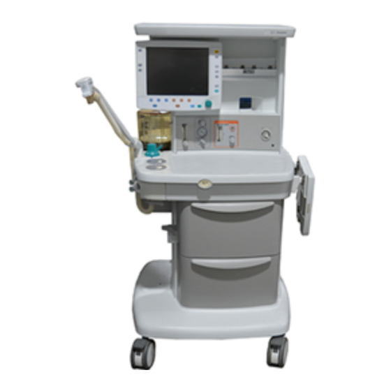
1 Introduction 1.3 What is an S/5 Avance anesthesia machine? The S/5 Avance anesthesia machine is a compact, integrated, and intuitive anesthesia delivery system. It provides electronic gas mixing and optional integrated respiratory gas monitoring. Figure 1-1 • S/5 Avance system... -
Page 16: Anesthesia System Components
S/5 Avance 1.4 Anesthesia system components 1. Anesthesia system display 2. Dovetail rails 3. Vaporizer 4. Alternate O 5. System switch 6. Brake 7. O flush button 8. Breathing system Figure 1-2 • Front view 11/03 1009-0357-000... - Page 17 1 Introduction 1. Outlet Circuit breaker (optional) 2. Electrical outlet (optional) 3. Cylinders supplies 4. Equipotential stud 5. Mains inlet 6. System circuit breaker 7. Pipeline connections Figure 1-3 • Rear view 1009-0357-000 11/03...
-
Page 18: Breathing System Components
S/5 Avance 1.5 Breathing system components 1. Expiratory check valve 2. Inspiratory check valve 3. ACGO (optional) 4. Inspiratory flow sensor 5. Expiratory flow sensor 6. Absorber canister 7. Absorber canister release 8. Leak test plug 9. Breathing system release 10. -
Page 19: Display Controls
1 Introduction 1.6 Display controls Silence Alarms Alarms Setup Help Main Menu Checkout Start/End Case Normal Gas Setup Vent Setup Screen Item Description Alarm silence key Push to silence any active, silenceable high and medium priority alarms. Alarm is silenced for 120 seconds. Menu keys Push to show corresponding menu. -
Page 20: Anesthesia System Display
S/5 Avance 1.7 Anesthesia system display 1. Electronic gas flow tubes 2. Alarm silence countdown 3. Alarm message fields 4. Waveform field 5. Clock 6. Number field 7. Free number display 8. Ventilator settings 9. Gas settings Figure 1-6 • Normal view... - Page 21 1 Introduction When a menu key is selected, the menu field overlays the gas flow tubes and the waveform fields start at the right edge of the menu. 1. Menu 2. Waveform fields Figure 1-7 • Menu view 1009-0357-000 11/03...
-
Page 22: Using Menus
Notes 1.7.1 Using menus Push a menu key to display the corresponding menu. Use the ComWheel to navigate through the menu. Xxxxxx Xxxxxx 1. Menu title 2. Present selection 3. Adjustment window 4. Indicates submenu 5. Short instructions 6. Menu selections Figure 1-8 •... -
Page 23: Symbols Used In The Manual Or On The Equipment
Cautions tell about a condition that can cause damage to the equipment. Read and follow all warnings and cautions. Other symbols replace words on the equipment or in Datex-Ohmeda manuals. No one device or manual uses all of the symbols. These symbols include:... - Page 24 S/5 Avance Plus, positive polarity Movement in one direction Minus, negative polarity Movement in two directions Variability Read top of float Variability in steps Vacuum inlet This way up Suction bottle outlet Lamp, lighting, illumination Cylinder Lock Isolation transformer Unlock...
- Page 25 Bypass active) European Council Directive (93/42/EEC) for Medical Devices when they are used as specified in their User’s Reference manuals. The xxxx is the certification number of the Notified Body used by European Union Representative Datex-Ohmeda’s Quality Systems. 1009-0357-000 11/03 1-13...
- Page 26 Notes 1-14 11/03 1009-0357-000...
-
Page 27: Theory Of Operation
2 Theory of Operation In this section 2.1 Electrical system ............2-2 2.2 Power subsystem . -
Page 28: Electrical System
S/5 Avance 2.1 Electrical system The electrical system consists of two main computing units: the Display Unit and the Anesthesia Control board. Additional subsystems interact with these computing hosts to perform various gas delivery, ventilation, and monitoring functions. The Display Unit handles the main user interface functions and connections to external devices. - Page 29 2 Theory of Operation 1009-0357-000 11/03...
-
Page 30: Power Subsystem
S/5 Avance 2.2 Power subsystem Mains power enters the system through the AC Inlet module (A), which includes a line filter and the system circuit breaker. Mains power is routed through the Inrush (B) circuit board to the isolation transformer (C). -
Page 31: Power Controller Board
2 Theory of Operation 2.2.1 Power Controller The system uses a distributed power bus. The Power Controller board contains: board • an AC/DC converter that converts line voltage to high voltage DC. • a DC/DC converter that converts the high voltage DC to battery voltage. •... -
Page 32: Power Distribution
S/5 Avance 2.2.2 Power distribution The Power Controller board provides outputs to the Anesthesia Control board and the Display Connector board. These boards provide local regulation of voltages required by the system. The Anesthesia Control board interfaces with the Mixer board and the Ventilator Interface board through the Pan Connector board. - Page 33 2 Theory of Operation Display Dispaly Unit CPU Board Power Controller Board Connector CPU 3.3V Board LCD 3.3V +4.1V Step Dwn +12.5V +12.5V CPU 2.5V (switched (switched bus PCMCIA 3.3V voltage) Mains voltage) PCMCIA 5V +22V CPU 5V +6.0V Step Dwn +3.3V FAN 5V +31V...
-
Page 34: Display Unit
S/5 Avance 2.3 Display Unit The Display Unit handles most of the machine’s user interface functions through the front panel controls and the LCD screen. It is the primary interface to external peripherals. The main components of the Display Unit include: •... -
Page 35: System Communications
2 Theory of Operation 2.4 System communications RS-422 serial communication is used between the two main processors — Display Unit and Anesthesia Computer — and the subsystem processors. Various baud rates accommodate data requirements between subsystem and host. External communication uses the standard RS-232 interface. Mgas Ventilator Intel '196Processor... -
Page 36: System Connections
S/5 Avance 2.5 System connections 2.5.1 Display Unit The Display Unit accommodates the following connections: • System Power Interface (1). • System Signal Interface (2). • Serial Port — standard interface for external communication (3). • DIS connector — supports D-O Device Interface Solution (DIS) (4). -
Page 37: Power Controller And Anesthesia Control Board Connections
2 Theory of Operation 2.6 Power Controller and Anesthesia Control board connections The Power Controller: • Distributes 12.5 VDC power and communicates with the Display Unit (by way of the Display Connector board) through the connector (10). • Distributes 12.5 VDC power to the Anesthesia Control board through connector (14). -
Page 38: Anesthesia Control Board
S/5 Avance 2.7 Anesthesia Control board The Anesthesia Control board (A) uses a Motorola MCF5307 Coldfire microcontroller with 4M Flash and 16M error correcting DRAM. The Anesthesia Control board includes 6 UARTs with a 64 byte FIFO and RS-422 communications to interface with the Display Unit, an accessory port, and anesthesia delivery subsystems located in the pan electronic enclosure. - Page 39 2 Theory of Operation ON/Standby and Mains LED 12.5VDC 10VA Power Vent +3.3V Supply Monitoring 12.5VDC 10VA Limit Circuitry Mixer Accessory SW Test LEDs +1.8V Supply MGAS Backup Accessory 1 Accessory 2 Audio and Sounder 12.5VDC +5V Supply Glue Logic O2 Select Gas Select Air Select...
-
Page 40: Electronic Gas Mixer
S/5 Avance 2.8 Electronic Gas Mixer The Gas Mixer receives its pneumatic inputs from the pipeline and cylinder supplies and sends mixed gas to the vaporizer manifold. The Gas Mixer interfaces to the Anesthesia Control board for power and communications. - Page 41 2 Theory of Operation Desired gas flows are sent from the Anesthesia Control board to the Gas Mixer. Gas Mixer operation is controlled through a microcontroller which: • Opens and closes selector valves for O O and Air. • Regulates flow control valves for O and balance gas (N O or Air).
-
Page 42: Ventilator Interface Board
S/5 Avance 2.9 Ventilator Interface board The Ventilator Interface board (A) provides the electrical and/or pneumatic interface to the following: • Inspiratory (B) and expiratory (C) flow sensors (transducers) • Patient airway (D) and manifold (E) pressures (transducers) • Oxygen sensor (in breathing system) •... - Page 43 2 Theory of Operation +12.5V Accessory Power +12.5V Valve Power Exp Data +12.5V C MUX Insp Data to Flow Sensors +5.0VA Filter +5.0V +5.0VDD Local Power Reg. +12.5V +6.0VA Supply Bag/Vent Sw -6.0VA Regulators O2 Flush Sw Emulator Activity Indicators Header O2 Disconnect Reset, Watchdog,...
-
Page 44: Gas Flow Through The Anesthesia Machine
S/5 Avance 2.10 Gas flow through the anesthesia machine 2.10.1 Overview Refer to Figure 2-20. Gas supplies Gas comes into the system through a pipeline (1) or cylinder (6) connection. All connections have indexed fittings, filters, and check valves (one-way valves). - Page 45 2 Theory of Operation A - Pipeline Manifold B - Cylinder Supply C - Gas Mixer D - Vaporizer Manifold E - SCGO Assembly F - ACGO Assembly P - Pressure Transducer Figure 2-20 • Pneumatic circuit 1009-0357-000 11/03 2-19...
- Page 46 S/5 Avance A - Pipeline Manifold B - Cylinder Supply C - Gas Mixer D - Vaporizer Manifold E - SCGO Assembly F - ACGO Assembly P - Pressure Transducer Figure 2-21 • Pneumatic circuit 2-20 11/03 1009-0357-000...
- Page 47 2 Theory of Operation Refer to Figure 2-21. Key to Numbered 1. Pipeline inlet Components 2. Pipeline pressure transducer 3. High-pressure relief valve (758 kPa / 110 psi)* 4. Supply connections for the ventilator and pilot pressure for SCGO a. O drive gas b.
-
Page 48: Physical Connections
S/5 Avance 2.10.2 Physical Figure 2-22 shows the physical path that the gas takes. The item numbers are described on the previous page. connections ACGO Port 3 SCGO Port 2 Port 3 Pilot Mixer Vacuum Pilot Suction To Vent Drive Figure 2-22 •... -
Page 49: Suction Regulators
2 Theory of Operation 2.10.3 Suction Pipeline vacuum regulators The suction regulator (shown in Figure 2-22) uses an external vacuum source. Venturi Drive vacuum The suction regulator (shown in Figure 2-23) uses an internal, venturi derived vacuum source. Drive gas (internally plumbed Air or O ) enters the Venturi Module (VM) at the drive port (A). -
Page 50: Flow Through The Breathing System
S/5 Avance 2.11 Flow through the breathing system 2.11.1 Overview of This section looks at three types of flow paths. flow paths • Ventilation paths: How gas flows from the drive source (bag or bellows) to and from the patient. -
Page 51: Manual Ventilation
2 Theory of Operation 2.11.2 Manual ventilation Manual inspiration The Bag/Vent switch closes the ventilator path (B)..(Figure 2-24) Gas flows from the bag (1), through the absorber (2), into the breathing circuit module, and through a unidirectional valve (inspiratory check valve) to the patient (3). During inspiration, fresh gas (FG) flows from the machine into the inspiratory limb, upstream of the inspiratory check valve. - Page 52 S/5 Avance Manual expiration The Bag/Vent switch keeps the ventilator path closed (B). (Figure 2-25) Gas flows from the patient (4), through a unidirectional valve (expiratory check valve), and into the bag (5). During exhalation, fresh gas flows backwards through the absorber (FG) into the expiratory limb, downstream of the expiratory check valve.
- Page 53 2 Theory of Operation APL Valve The APL valve sets a pressure limit for manual ventilation. (Figure 2-26) As you turn the APL knob, it puts more or less force on the APL disc and seat (D/S). If the circuit pressure is too high (6), the disc and seat inside the diaphragm opens and vents gas to the scavenging system (7).
-
Page 54: Mechanical Ventilation
S/5 Avance 2.11.3 Mechanical ventilation Mechanical inspiration The Bag/Vent switch closes the manual path (V). Pilot pressure (P) closes the (Figure 2-27) exhalation valve. Drive gas (D) pushes down on the bellows. Gas flows from the bellows (1), through the absorber (2), and through a unidirectional valve (inspiratory check valve) to the patient (3). - Page 55 2 Theory of Operation Mechanical expiration Drive-gas flow stops and the exhalation valve opens. Exhaled gas flows from the (Figure 2-28) patient (4), through a unidirectional valve (expiratory check valve) and into the bellows (5). Residual drive gas (D) flows out of the bellows to the scavenging system (6). If PEEP is selected, static pressure on the pilot port of the exhalation valve sets the PEEP level.
- Page 56 S/5 Avance Pop-off valve The pop-off valve limits the pressure inside the bellows to 2.5 cm H O above the drive (Figure 2-29) gas pressure. This normally occurs when the bellows reaches the top of the housing at the end of exhalation.
-
Page 57: Fresh Gas And O Flush Flow (With Scgo)
2 Theory of Operation 2.11.4 Fresh gas and O flush flow (with SCGO) To ABS (Circle) Fresh gas (1) flows from the vaporizer manifold outlet to the SCGO assembly. breathing system With the Circle system selected, fresh gas flow is channeled to Port 3 of the breathing (Figure 2-30) system (before the inspiratory check valve). - Page 58 S/5 Avance Switched (Non-circle) Fresh gas (1) flows from the vaporizer manifold outlet to the SCGO assembly. Common Gas Outlet With the Non-Circle system selected, fresh gas flow is channeled to Port 2 of the (Figure 2-31) breathing system (after the inspiratory check valve - to an external patient circuit through the Inspiratory port).
-
Page 59: Fresh Gas And O 2 Flush Flow (With Acgo)
2 Theory of Operation 2.11.5 Fresh gas and O flush flow (with ACGO) To ABS (Circle) Fresh gas (1) flows from the vaporizer manifold outlet to the ACGO Selector Switch. breathing system With the ACGO Selector Switch in the ABS position, fresh gas flow is channeled to the (Figure 2-32) breathing system. - Page 60 S/5 Avance Auxiliary (Non-circle) Fresh gas (1) flows from the vaporizer manifold outlet to the ACGO Selector Switch. Common Gas Outlet With the ACGO Selector Switch in the ACGO position, fresh gas flow is channeled to the (Figure 2-33) ACGO outlet.
-
Page 61: Ventilator Mechanical Subsystems
2 Theory of Operation 2.12 Ventilator mechanical subsystems Refer to Figure 11-1, "System circuit diagram" in Section11, for the complete pneumatic/mechanical subsystem diagram. The mechanical subsystems for the ventilator include: Pneumatic Vent Engine • Drive gas inlet filter • Gas inlet valve •... -
Page 62: Pressure Regulator
S/5 Avance 2.12.2 Pressure The pressure regulator (4) is a non-relieving pressure regulator that regulates high pressure filtered supply gas down to 172 kPa (25 psi). regulator (2.0 cm (3.5 cm H2O bias) Inspiratory Flow Control Valve ernate O2 sable Valve... -
Page 63: Drive Gas Check Valve (Dgcv)
2 Theory of Operation 2.12.4 Drive Gas The Drive Gas Check Valve (6) is used downstream of the flow control valve to create the pilot pressure for closing the exhalation valve during inspiratory phases, The DGCV Check Valve valve is biased shut by an integral weight that supplies approximately 3.5 cm H O of (DGCV) bias pressure before permitting flow downstream to the breathing circuit. -
Page 64: Exhalation Valve
S/5 Avance 2.12.6 Exhalation The exhalation valve contains an elastomeric diaphragm that is used along with the flow valve to control the pressures in the breathing circuit. The exhalation valve valve includes two male ports on the bottom for: • Bellows drive gas (8) •... -
Page 65: Mechanical Overpressure Valve
2 Theory of Operation 2.12.7 Mechanical The Mechanical Overpressure Valve (MOPV) is a mechanical valve (14) that operates regardless of electrical power. It functions as a third level of redundancy to the Overpressure Valve ventilator's pressure limit control functions, supplying pressure relief at approximately 110 cm H Vent Engine Atmosphere... -
Page 66: Free Breathing Valve
S/5 Avance 2.12.9 Free The free breathing valve (17) helps assure the patient can spontaneously breathe. The ventilator is programmed to supply a specified number of breaths per minute to the breathing valve patient. If, in between one of these programmed cycles, the patient needs a breath (spontaneous), the free breathing valve permits the patient to inhale. -
Page 67: Checkout Procedure
3 Checkout Procedure In this section 3.1 Inspect the system ............3-2 3.2 System “All checks”... -
Page 68: Inspect The System
S/5 Avance 3.1 Inspect the system w w w w CAUTION The upper shelf weight limit is 34 kg (75 lb). w w w w WARNING Do not leave gas cylinder valves open if the pipeline supply is in use. -
Page 69: System "All Checks
3 Checkout Procedure 3.2 System “All checks” On the system “Checkout” menu, select All Checks and follow the instructions for “Low P leak check”, “Quick check”, “Vent check”, and “Circuit O2 cell check”. If a check fails, follow the instructions on the display to perform a recheck or accept the results. -
Page 70: Quick Check
S/5 Avance 3.2.2 Quick check The quick check checks that the: • Bag/Vent switch works in Bag position. • Gas supply pressures are OK. • Power cord is connected and the mains power is OK. • Battery is fully charged. -
Page 71: Backlight Test
3 Checkout Procedure 3.3 Backlight test Main Menu 1. Push the key. 2. Select Calibration. 3. Select Backlight Test. 4. Select Start Test. 5. The display will show the test running on light 1 and then on light 2. If the display goes completely blank or flickers during the test, one of the lights has failed. -
Page 72: Pipeline And Cylinder Tests
S/5 Avance 3.5 Pipeline and cylinder tests 1. Connect the pipeline supplies one at a time and ensure that the corresponding display indicates pipeline pressure. 2. Disconnect all pipeline supplies. a. Open each cylinder valve. b. Make sure that each cylinder has sufficient pressure. If not, close the applicable cylinder valve and install a full cylinder. -
Page 73: Pressure Relief Tests
3 Checkout Procedure 3.6 Pressure relief tests To check the pressure relief valve in the vaporizer manifold outlet. For machines with SCGO: 1. Remove the back cover to access the vaporizer manifold. 2. Remove the outlet tubing and connect a test device (pressure gauge or a digital manometer) to the vaporizer manifold outlet. -
Page 74: Flush Flow Test
S/5 Avance 3.7 Flush Flow Test 1. Set the Bag/Vent switch to Vent. 2. Set the system switch to Standby. 3. Attach a patient circuit and plug the patient port. 4. For ACGO equipped machines, set the ACGO selector switch to ABS. -
Page 75: Alarm Tests
3 Checkout Procedure 3.8 Alarm tests 1. Connect a test lung to the patient connection. 2. Start a case. 3. Set the Bag/Vent switch to Vent. 4. Set the O concentration to 30%, and allow the O reading to stabilize. 5. -
Page 76: Alternate O Flowmeter Tests
S/5 Avance 3.9 Alternate O flowmeter tests 1. Open the O cylinder valve or connect an O pipeline. 2. Rotate the Alt O flow control fully clockwise to minimum flow. 3. Press the Alternate O switch to turn on Alternate O flow. -
Page 77: Power Failure Test
3 Checkout Procedure 3.12 Power failure test 1. Connect the power cord to a wall outlet. The mains indicator on the front panel comes on when AC Power is connected. 2. Set the system switch to On and Start a case. 3. - Page 78 Notes 3-12 11/03 1009-0357-000...
-
Page 79: Installation And Service Menus
4 Installation and Service Menus In this section 4.1 Service and Installation menu structure ........4-2 4.2 Install/Service Menu (Super User) . -
Page 80: Service And Installation Menu Structure
S/5 Avance 4.1 Service and Installation menu structure This section describes the Service level functions that are part of the main software installed in the anesthesia machine. Section 8, “Service Diagnostics and Software Download,” covers a separate service application that loads from a PCMCIA card and is used to download system software and run service diagnostics and other service tests. -
Page 81: Install/Service Menu (Super User)
4 Installation and Service Menus 4.2 Install/Service Menu (Super User) Use the super-user password to access the Install/Service menu: “16-4-34.” Menu Item Message text Comments Colors Set colors of parameters. Units Set units of weight, CO2, gas supply pressure, and Paw. Show Alarm Limits Select yes to show alarm limits in Default is Yes... -
Page 82: Colors Menu
S/5 Avance 4.2.1 Colors Menu Menu Item Message text Values Change color of Paw waveform, Yellow, White, digits and trend. Green, Red, or Blue Flow Change color of Flow waveform, Flow Yellow, White, and Volume digits and trends. Green, Red,... -
Page 83: Factory Defaults
4 Installation and Service Menus 4.2.3 Factory Defaults The following table lists the factory defaults for parameters and alarm limits: Parameter Value Alarm Limit Value Vent Mode Pmax High 40 cmH2O (40 hPa, 4 kPa, 40 mbar, 30 mmHg) TV (tidal volume) 500 ml MV High 10 l/min... -
Page 84: Installation Menu
S/5 Avance 4.3 Installation Menu Use the service-level password to access the Installation menu: “26-23-8.” Whenever the installation menu is entered, “Enter Service dd-mmm-yyyy hh:mm:ss” is recorded in the Event log. Menu Item Message text Configuration Set language, gas color code, and O2 flowmeter position. -
Page 85: Configuration
4 Installation and Service Menus 4.3.1 Configuration Menu Item Message text Values Comments Decimal Marker Select decimal 0.01, 0 01 or 0,01 delineator. Language Change language English, French, Default: English translation of screen German, Spanish, texts. Italian, Japanese, Portuguese, Dutch, Chinese (simplified), Finnish, Norwegian, Hungarian, Polish,... -
Page 86: Units Menu
S/5 Avance 4.3.2 Units Menu This is the same menu that is accessible from the super-user Install/Service menu. Menu Item Message text Values Weight Change weight unit: kg or lb. kg or lb Change CO2 unit: %, kPa, or mmHg. -
Page 87: Copy Configuration
4 Installation and Service Menus Options List menu The options list shows which options are enabled. Menu Item Message text Values Available Options SIMV/PSV SIMV vent w/pressure support. On, Off Pressure controlled ventilation. On, Off PSV Pro Pressure support ventilation w/backup. On, Off 4.3.4 Copy Configuration Copy Configuration menu... -
Page 88: Service Menu
S/5 Avance 4.4 Service Menu Use the service-level password to access the Service menu: “26-23-8.” Whenever service menu is entered, “Enter Service dd-mmm-yyyy hh:mm:ss” is recorded in the Event log. Menu Item Message text SW HW versions Scroll through system information. -
Page 89: Software/Hardware Ver Menu
4 Installation and Service Menus 4.4.1 Software/ Turn the ComWheel to scroll through the list box. Hardware Ver Menu Push the ComWheel to return to the Service menu. System Information menu List box text with X=Number, A, B, C = letter Total Time: XXXXX (Minutes) Software Release: XX.XX Model Code: XXX... -
Page 90: Service Log Menu
S/5 Avance 4.4.2 Service Log Menu The Service log menu is a organized listing of stored events. Menu Item Message text Scroll Recent Scroll through newest entries. Error History Show error history. Event History Show event history. Alarm History Show alarm history. -
Page 91: Calibration
4 Installation and Service Menus 4.4.3 Calibration For step-by-step instruction, refer to Section 5. Menu Item Message text Instructions User Calibration Show the normal user calibration menu. Manifold P Span Calibrate manifold pressure transducer. Insp Flow Zero Zero inspiratory flow valve. Insp Flow Valve Calibrate inspiratory flow valve. -
Page 92: Manifold P Span
S/5 Avance 4.4.4 Manifold P Span The Manifold P Span instructions appear when the focus is on Manifold P Span menu item. Instructions Read all steps before you start: 1. Remove the breathing system, the exhalation valve, and the metal plate. -
Page 93: Insp Flow Zero
4 Installation and Service Menus 4.4.5 Insp Flow Zero The Insp Flow Zero instructions appear when the focus is on the Insp Flow Zero menu item. Instructions Read all steps before you start: 1. Push the ComWheel to start the zero check 2. -
Page 94: Inspiratory Flow Valve
S/5 Avance 4.4.6 Inspiratory Flow The Inspiratory Flow Valve instructions appear when the focus is on the Insp Flow Valve menu item. Valve Instructions Read all steps before you start: 1. Complete the Manifold P Span calibration. 2. Put #2 plugs in the manifold and the drive gas ports of the vent engine. - Page 95 4 Installation and Service Menus Insp Flow Valve Menu Menu Item Message text Comments Stage 1 Calibrate the insp flow valve at low Blocked if the flows. ventilator drive gas supply Blocked text: pressure would “Connect a supply of the drive gas to cause a gas continue.”...
-
Page 96: Bleed Resistor
S/5 Avance 4.4.7 Bleed Resistor The Bleed Resistor instructions appear when the focus is on the Bleed Resistor menu item. Instructions Read all steps before you start: 1. Complete the Insp Flow Valve calibration. 2. Put #2 plugs in the manifold and the drive gas ports of the vent engine. -
Page 97: Paw Span
4 Installation and Service Menus 4.4.8 Paw Span The Airway P Span instructions appear when the focus is on Paw Span menu item. Instructions Read all steps before you start: 1. Complete the Bleed Resistor calibration. 2. Install the flow sensor and circuit module 3. -
Page 98: Zero Gas Xducer
S/5 Avance 4.4.9 Zero Gas Xducer The Zero Gas Xducer instructions appear when the focus is on the Zero Gas Xducer menu item. Instructions Read all steps before you start: 1. Remove all cylinders. 2. Disconnect all pipeline supplies. 3. Select Zero Gas Xducers. -
Page 99: Cal Config
4 Installation and Service Menus 4.4.10 Cal Config Before calibration, you must verify that the Ventilator Drive Gas and the Altitude settings are set appropriately to match the current drive gas configuration and machine location. If you change any of the settings in the Cal Config menu, you must restart the system. - Page 100 Notes 4-22 11/03 1009-0357-000...
-
Page 101: Calibration
5 Calibration WARNING After adjustments and calibration are completed, always perform the checkout procedure. Refer to Section 3 of this manual. In this section 5.1 Primary Regulators ............5-2 5.1.1 Test setup . -
Page 102: Primary Regulators
S/5 Avance 5.1 Primary Regulators Follow the procedure in Section 5.1.1 to gain access to the regulators. Then, in Section 5.1.2, select the test that is appropriate for the regulator you are testing. w w w w WARNING When testing/adjusting N O regulators, nitrous oxide flows through the system. -
Page 103: Test Setup
5 Calibration 5.1.1 Test setup w w w w WARNING Wear safety glasses while test device is connected to the test port. w w w w CAUTION Be careful not to plug the output of the primary regulator without having a pressure relief valve in the output circuit. - Page 104 S/5 Avance Test A For primary regulators that supply drive gas to the ventilator (O or Air): Under low flow conditions, the output pressure of a properly adjusted/ functioning regulator should fall within specifications listed in step 4e. Under high flow conditions, the output pressure should not drop below the specifications listed in step 5g.
- Page 105 5 Calibration f. Adjust the Flow Valve counts until the Flow Valve Setting at the bottom of the screen reads 65 l/min. g. While watching the test device, toggle the Gas Inlet Valve several times (Closed, Open, Closed): • Press the ComWheel to return focus to the selection menu. •...
- Page 106 S/5 Avance Test B For all gases not used to supply drive gas to the ventilator: Under low flow conditions, the output pressure of a properly adjusted/ functioning regulator should fall within specifications listed in step 4e. Under high flow conditions, the output pressure should not drop below the specifications in step 5b.
- Page 107 5 Calibration 6. Set the system switch to Standby. 7. Close the cylinder valve. 8. Bleed the system of all pressure. 9. Disconnect the test device and plug the test port (pull on the plug to ensure it is locked in the fitting). 10.
-
Page 108: Adjusting Primary Regulators
S/5 Avance 5.1.3 Adjusting Primary Important: Cylinder supplies in an S/5 Avance machine must have all primary regulators set to the same pressure range: Regulators (50) Pin Indexed or (60) DIN. If a regulator is replaced, the replacement regulator must be set (as required) to the same specification as the one removed. -
Page 109: Flush Regulator
5 Calibration 5.2 O Flush Regulator 1. Bleed all gas pressure for the machine (Section 9.1). 2. Remove the upper rear panel (Section 9.2). 3. Remove the O Flush Regulator output tubing. Attach a 6-mm tee and a test device to the open port. Remove output tubing Attach 6-mm tee and test device Jam nut... -
Page 110: Adjust Drive Gas Regulator
S/5 Avance 5.3 Adjust Drive Gas Regulator The drive gas regulator must be adjusted while maintaining a flow of 15 l/min. To adjust the flow, you must boot the system with the PCMCIA Service Application and access the Vent Diagnostics function as detailed in Section 8. -
Page 111: Ventilator Calibrations
5 Calibration 5.4 Ventilator Calibrations Before performing the ventilator calibrations, verify that the drive gas regulator is adjusted to specifications (Section 5.3). The Service menu structure is detailed in Section 4. To access the Ventilator Calibrations menu: 1. Turn on the system. 2. -
Page 112: Manifold P Span
S/5 Avance 5.4.2 Manifold P Span Calibration setup: 1. Remove the ABS breathing system from the machine. 2. Remove the Exhalation Valve. 3. Remove the Vent Engine cover. 4. Plug the Drive Port (A) and the Manifold Port (B) on the Vent Engine interface valve. -
Page 113: Inspiratory Flow Valve Cal
5 Calibration 5.4.4 Inspiratory Flow Valve Cal Calibration setup Leave the Drive Port (A) and the Manifold Port (B) on the interface valve plugged. Calibration procedure: 1. On the Calibration menu, select Insp Flow Valve. 2. Push the ComWheel to enable the Stage 1 calibration. 3. -
Page 114: Paw Span
S/5 Avance 5.4.6 Paw Span Calibration setup 1. Leave the Drive port (A) port plugged. 2. Remove the plug from the Manifold port. 3. Attach a patient circuit tube to the Calibrated Flow Orifice. 4. Insert the Calibrated Flow Orifice into the Manifold port (B). -
Page 115: Maintenance
6.1 S/5 Avance Planned Maintenance ........ -
Page 116: S/5 Avance Planned Maintenance
S/5 Avance 6.1 S/5 Avance Planned Maintenance Serial Number: Date: (YY/MM/DD) Hospital: Performed by: 12 months 24 month 48 month ______________________ 6.1.1 Every twelve (12) Perform the following steps every 12 months. For details, refer to the sections listed. months •... -
Page 117: Every Twenty-Four (24) Months
6 Maintenance 12. Mixer flow verification test (TRM - Section 6.5.2) 13. Perform the following diagnostics using the PCMCIA Service Application. • Display Diagnostics (TRM - Section 8.4). • MOPV pressure relief valve test (TRM - Section 6.3). • Pressure Limit Circuit test (TRM - Section 6.4). •... -
Page 118: Free Breathing Valve Maintenance
S/5 Avance 6.2 Free breathing valve maintenance 1. Unscrew the valve seat ( ) from the side of the interface manifold. 2. Inspect the flapper ( ) and valve seat for nicks, debris and cleanliness. To replace the flapper valve 3. -
Page 119: Mopv Pressure Relief Valve Test
6 Maintenance 6.3 MOPV pressure relief valve test WARNING Objects in the breathing system can stop gas flow to the patient. This can cause injury or death: • Do not use a test plug that is small enough to fall into the breathing system. -
Page 120: Pressure Limit Circuit Test
S/5 Avance 6.4 Pressure Limit Circuit test To perform the test: • establish a closed patient airway circuit. • increment the pressure in the airway circuit. • observe the output of the airway pressure transducer. • note that the “pressure limit circuit” trips at approximately 109 cmH Test setup 1. - Page 121 6 Maintenance Test Procedure 1. On the Main Menu of the Service Application, select Vent Diagnostics. 2. On the Vent Diagnostics menu, select Status and verify that “Over Pressure Circuit” reads OK. 3. Press the ComWheel to return focus to the selection menu. 4.
-
Page 122: Mixer Test
S/5 Avance 6.5 Mixer test To perform the mixer tests, you must gain access to the mixer outlet tubing which is connected to the inlet of the vaporizer manifold. 1. Remove the rear cover. 2. Disconnect the mixer outlet tube at the inlet to the vaporizer manifold. -
Page 123: Alternate O Flowmeter Tests
6 Maintenance 6.6 Alternate O flowmeter tests 1. Open the O cylinder valve or connect an O pipeline. 2. Rotate the Alt O flow control fully clockwise to minimum flow. 3. Press the Alternate O switch to turn on Alternate O flow. -
Page 124: Auxiliary O Flowmeter Tests
S/5 Avance 6.7 Auxiliary O flowmeter tests 1. Open the O cylinder valve or connect an O pipeline. 2. Rotate the flow control clockwise (decrease) to shut off the flow. The ball should rest at the bottom of the flow tube and not move. -
Page 125: Integrated Suction Regulator Tests
6 Maintenance 6.8 Integrated Suction Regulator tests Note There are two types of integrated suction systems for the Avance anesthesia machine: • Continuous Vacuum Regulator, Three-Mode, Pipeline Vacuum • Continuous Vacuum Regulator, Three-Mode, Venturi Derived Vacuum For Pipeline Vacuum systems, a vacuum source of at least 500 mm Hg (67 kPa or 20 in Hg) is required for testing. - Page 126 S/5 Avance Regulation Test 1. Turn the mode selector switch to I (ON). 2. Occlude the patient port of the suction regulator. 3. Set the vacuum regulator gauge to 100 mm Hg/13 kPa. 4. Open and close the patient port several times.
-
Page 127: Battery Capacity Test
6 Maintenance 6.9 Battery capacity test Although replacement of the backup batteries is recommended at the end of 4 years, batteries that pass the capacity test can be considered viable for battery backup of the system for up to 6 years at the discretion of the hospital. Before testing the batteries, ensure that they are fully charged. - Page 128 Notes 6-14 11/03 1009-0357-000...
-
Page 129: Troubleshooting
7 Troubleshooting In this section 7.1 General Troubleshooting ........... . .7-2 7.2 Breathing System Leak Test Guide . -
Page 130: General Troubleshooting
S/5 Avance 7.1 General Troubleshooting WARNING Objects in the breathing system can stop gas flow to the patient. This can cause injury or death: • Do not use a test plug that is small enough to fall into the breathing system. - Page 131 7 Troubleshooting Problem Possible Cause Action Low Pressure Leak Leaking port valve on vaporizer manifold Use the Vaporizer Manifold Valve Tester to check for leak. (with or without vaporizer) See Section 9.12.2 for instructions. If test fails, tighten, repair, or replace as needed. Leak in mixer If vaporizer manifold passed previous tests: Remove tubing from inlet port of vaporizer manifold...
-
Page 132: Breathing System Leak Test Guide
S/5 Avance 7.2 Breathing System Leak Test Guide Note Always do the System “All Checks” (Section 3.2) on the machine before proceeding with these breathing system leak tests. • The Low P leak check looks for leaks between the mixer, vaporizer, and the inspiratory side of the breathing circuit. -
Page 133: Check Valves
7 Troubleshooting 7.2.1 Check Valves Make sure that the check valves on the breathing circuit module work correctly: The Inspiratory check valve rises during inspiration and falls at the start of expiration. The Expiratory check valve rises during expiration and falls at the start of inspiration. -
Page 134: Breathing System Troubleshooting Flowcharts
S/5 Avance 7.2.2 Breathing System Troubleshooting Flowcharts Start (Section 7.2) Review Leak Test Guide • Do System “All Checks” • Isolate breathing system leak to Bag Mode,Vent Mode, or Both Perform Leak Test 1 Verifying the integrity of test tools... - Page 135 7 Troubleshooting Leak in Bag Mode only Perform Test 4 Testing the bag port, Pass APL Valve, and Bag/Vent Switch, and Negative Pressure Relief Valve Re-Install all breathing circuit components and repeat Fail System “All Checks” (Section 3.2) Check or Replace Does the the Bag/Vent Bellows...
- Page 136 S/5 Avance Leak in Vent Mode only Perform Test 6 Pass Testing the bellows assembly, and Bag/Vent Switch Perform Test 8 Inspect Exhalation Valve Testing the bellows and and Drive Circuit bellows Pop-off Fail Pass Re-Install all breathing circuit components and repeat System “All Checks”...
- Page 137 7 Troubleshooting Leak in both Bag and Vent Mode Common Areas: Flow Sensor Module, Circuit Module, Soda Lime Canister, Negative Pressure Relief Perform Test 9 Testing the Flow Sensor Fail Pass Module, Circuit Module, and Soda Lime Canister Perform Test 13 Perform Test 10 Testing the Testing the Circuit...
- Page 138 S/5 Avance Leak in Flow Sensor Module or Circuit Module Perform Tests 14 and 15 Testing the Flow Sensors Fail Pass using the low-pressure leak test device Check/Replace Check/Replace the seals Flow Sensors or on the Circuit Module and bulkhead connector...
-
Page 139: Leak Isolation Tests
7 Troubleshooting 7.2.3 Leak Isolation Tests The previous flowcharts refer you to the following tests. These tests require the use of the Low Pressure Leak Test Device and the Leak Test Tool Kit (refer to Section 10.1, "Service tools"). The Leak Test Tool Kit includes: •... - Page 140 S/5 Avance Test 1 Verifying the integrity of the test tools Machine Test Tool Front View Bulb Thru Port (not connected to airway path) Pressure Sense Port Fresh Gas Port Alignment Post Back View Bulb Thru Port 1. Verify integrity of low-pressure leak test device.
- Page 141 7 Troubleshooting Test 2 Low-pressure leak testing the machine 1. Remove the breathing system from the machine. 2. Attach the Machine Test Tool (using only the Thru Port) and the low- pressure leak test device to Port 3 of the breathing system interface as shown above.
- Page 142 S/5 Avance Test 3 Testing the airway pressure transducer, and Port 1 and Port 3 u-cup seals Alignment Post 1. On the Main Menu of the Service Application, select Gas Diagnostics. 2. On the Gas Diagnostics page, select O2 Flow.
- Page 143 7 Troubleshooting Test 4 Testing the bag port cover, the APL valve, the Bag/Vent switch, and the negative pressure relief valve Plug Bag Port 1. Separate the Bellows Module from the Circuit Module and re-install the Bellows Module. 2. Occlude the Bag Port connector. 3.
- Page 144 S/5 Avance Test 5 Testing the APL diaphram Plug Scavenging Port Plug Bag Port Note If required, set up the Machine Test Tool and breathing system as shown in Test 4. 1. Slide the Bellows Module away from the machine.
- Page 145 7 Troubleshooting Test 6 Testing the bellows module and the Bag/Vent switch 1. Separate the Bellows Module from the Circuit Module and re-install the Bellows Module. 2. Connect the Machine Test Tool to the interface ports as shown above. 3. Set the Bag/Vent switch to the Vent position. 4.
- Page 146 S/5 Avance Test 7 Testing the bellows, the bellows pop-off valve, the bellows base manifold, and the Bag/Vent switch 1. Separate the Bellows Module from the Circuit Module. 2. Insert appropriate test plugs into the bellows base manifold as shown to the left.
- Page 147 7 Troubleshooting Test 8 Testing the bellows assembly Note If required, set up the Machine Test Tool and breathing system as shown in Test 7. 1. Remove the bellows base manifold from the Bellows Module. 2. Insert appropriate test plugs into the bellows base manifold as shown to the left.
- Page 148 S/5 Avance Test 9 Testing the flow sensor module, the circuit module, and the soda lime canister Plug 1. Separate the Bellows Module from the Circuit Module and re-install the Circuit/Flow Sensor Module. 2. Connect short tubing between the inhalation and exhalation ports of the breathing system.
- Page 149 7 Troubleshooting Test 10 Testing the circuit module and the canister 1. Remove the Flow Sensor module. 2. Connect the Circuit Test Tool to the Circuit Module as shown above. 3. Set O Flow to 0.2 l/min. 4. On the Gas Diagnostics page, reselect the O2 Flow screen. •...
- Page 150 S/5 Avance Test 12 Testing the inspiratory side of the circuit module Plug Loop Note: If required, set up the machine as in Test 10 and 11. 1. Connect the Circuit Test Tool to the Circuit Module as shown above.
- Page 151 7 Troubleshooting Test 13 Testing the negative pressure relief valve 1. Separate the Bellows Module from the Circuit Module. 2. Remove the Bellows Interface Manifold. 3. Insert test plug (recessed end) into the rear Bag/Vent switch port as shown. Plug 4.
- Page 152 S/5 Avance Test 14 Testing the flow sensors only 1. Remove the Flow Sensor Module. 2. Plug each Flow Sensor as shown above. 3. Connect the low-pressure leak test device to the open end of the Flow Sensor. 4. Block the connector end of the Flow Sensor with your hand.
- Page 153 7 Troubleshooting Test 15 Testing a flow sensor including the Ventilator Monitoring Assembly and interfacing components 1. Remove Flow Sensors from the Flow Sensor Module. 2. Attach the Flow Sensor to the bulkhead connector. 3. Plug each Flow Sensor as shown. 4.
-
Page 154: Technical Alarms
Notes 7.3 Technical Alarms The Error Log includes technical alarms and other error conditions reported by the system. A technical alarm, as apposed to a parameter alarm, is an alarm condition that exists wether or not a patient is connected to the machine. Technical alarms include: •... - Page 155 7 Troubleshooting Error Log Entry Alarm Text Condition (Basic info) Priority Source Enabling Criteria Action/Troubleshooting +12.0V H AMPS MGAS Gas monitoring not Status bit shows current high. Medium MGAS 10 VA is turned available Remove Gas Module from the Module Bay. If the problem continues, replace the M-Gas Monitoring board.
- Page 156 S/5 Avance Error Log Entry Alarm Text Condition (Basic info) Priority Source Enabling Criteria Action/Troubleshooting ACB COM FAIL System Malfunction After establishing initial High communication, the DC does not receive any messages from AC in 10 sec. Reboot System. If problem continues, replace the ACB.
- Page 157 7 Troubleshooting Error Log Entry Alarm Text Condition (Basic info) Priority Source Enabling Criteria Action/Troubleshooting ACB SW WATCHDOG System Malfunction Software watchdog failed power- High up test, timed out, or a software function was delinquent for too long. Reboot System. If problem continues, replace the ACB. ACB UNEXPECTED System Malfunction Unexpected reset of AC...
- Page 158 S/5 Avance Error Log Entry Alarm Text Condition (Basic info) Priority Source Enabling Criteria Action/Troubleshooting AUX OUTLET FAIL No fresh gas flow? The measured SCGO position High does not match commanded Vent position. In the Service Software / Vent Diagnosis, view the Circuit Feedback status. If the feedback indicates “Fault”, toggle the Circuit.
- Page 159 7 Troubleshooting Error Log Entry Alarm Text Condition (Basic info) Priority Source Enabling Criteria Action/Troubleshooting BATTERY EMPTY System shutdown in Available battery power is High AC Mains Power Failure <5 min between 1 and 5 minutes in progress. Leave the system plugged in to charge the battery. If problem continues, check the battery charge circuit in Service Software.
- Page 160 S/5 Avance Error Log Entry Alarm Text Condition (Basic info) Priority Source Enabling Criteria Action/Troubleshooting BELLOWS COLLAPSED Unable to drive bellows Manifold pressure > Paw + 10 + In range Paw and (0.25* Inspiratory valve flow) Vent manifold pressure data...
- Page 161 7 Troubleshooting Error Log Entry Alarm Text Condition (Basic info) Priority Source Enabling Criteria Action/Troubleshooting DRIVE GAS LOST Ventilator has no drive supply low if O is selected High Mechanical Ventilation is ON. drive gas checks enable AIR supply low if Air is selected criteria drive gas.
- Page 162 S/5 Avance Error Log Entry Alarm Text Condition (Basic info) Priority Source Enabling Criteria Action/Troubleshooting INSP FLOW SENSOR Replace insp flow EEPROM cal data read failure EEPROM FAILURE sensor Vent Replace the Inspiratory Flow Sensor. LOSS OF GAS After regular communications...
- Page 163 7 Troubleshooting Error Log Entry Alarm Text Condition (Basic info) Priority Source Enabling Criteria Action/Troubleshooting MANIFOLD PAW Vent Fail. Monitoring Calibration failure at bootup Medium SENSOR FAIL Only Vent In the Service Software / Vent Flow & Pressure Diagnostics, verify the Manifold Flow counts is 800 ±...
- Page 164 S/5 Avance Error Log Entry Alarm Text Condition (Basic info) Priority Source Enabling Criteria Action/Troubleshooting MGAS LINE BLOCKED Sample line blocked MGAS SPEC states The sample Medium MGAS MGAS present and >20 SEC tubing inside or outside the MGAS communicates...
- Page 165 7 Troubleshooting Error Log Entry Alarm Text Condition (Basic info) Priority Source Enabling Criteria Action/Troubleshooting MIXER ACB COM Alternate O Screen. Mixer status Bit Medium FAILLOST CMD STS_LOSS_OF_SETFLOW_CMD. Mixer Mixer has lost AC flow commands for 5 sec or received “illegal” commands.(hypoxic mix, settings not allowed) Reboot System.
- Page 166 S/5 Avance Error Log Entry Alarm Text Condition (Basic info) Priority Source Enabling Criteria Action/Troubleshooting MIXER CRC EEPROM Alternate O Screen Runtime CRC check on EEPROM Medium FAIL failed. Mixer Status Bit Mixer STS_EEPROM_CRC_FAIL Reboot System. If problem continues, replace the Mixer.
- Page 167 7 Troubleshooting Error Log Entry Alarm Text Condition (Basic info) Priority Source Enabling Criteria Action/Troubleshooting MIXER O2 ZERO LEAK Mixer status bit Medium FAIL STS_CH1_ZERO_FLOW_TESPRO Mixer PN_V_LEAK_FAILT_FAIL. O proportional valve fails zero flow checks for leaks when it should be closed. Reboot System.
- Page 168 S/5 Avance Error Log Entry Alarm Text Condition (Basic info) Priority Source Enabling Criteria Action/Troubleshooting N2O PRESS LOW O supply pressure O pipeline pressure is less O is selected as the than 252 kPa and the N balance gas with a non...
- Page 169 7 Troubleshooting Error Log Entry Alarm Text Condition (Basic info) Priority Source Enabling Criteria Action/Troubleshooting O2 SENSOR FAILURE Replace O sensor < 5% Galvanic O sensor Vent connected Calibrate O Sensor. If calibration fails, replace O Sensor. If calibration continues to fail, wait 90 minutes and repeat calibration. If calibration fails after 90 minute, replace VIB O2CAL ERROR Calibrate O...
- Page 170 S/5 Avance Error Log Entry Alarm Text Condition (Basic info) Priority Source Enabling Criteria Action/Troubleshooting REVERSE EXPIRATORY Reverse exp flow. Flow towards the patient (volume Medium AC Vent In-range flow data FLOW Check valves OK? >= 20 mL) on expiratory sensor...
- Page 171 7 Troubleshooting Error Log Entry Alarm Text Condition (Basic info) Priority Source Enabling Criteria Action/Troubleshooting VENT +6V FAIL Vent Fail. Monitoring VSIB +6V out of range<5.51 Vdc High Vent +12.5 V (10 VA) is Only or > 6.5 Vdc Vent In the Service Software / Vent Interface Bd Power Diagnosis, view the “Vent Int Bd 10VA Voltage”...
- Page 172 S/5 Avance Error Log Entry Alarm Text Condition (Basic info) Priority Source Enabling Criteria Action/Troubleshooting VENT VALVE POWER Vent Fail. Monitoring Nominal 12.5V <11.3 V or Medium FAIL Only >13.13Vdc Vent In the Service Software / Vent Interface Bd Power Diagnosis, view the “Vent Int Bd 10VA Voltage” from Board Supplies: If “Vent Int Bd 10VA Voltage”...
-
Page 173: Steps And Messages Displayed During The System Checkout
7 Troubleshooting 7.4 Steps and Messages displayed during the System Checkout 7.4.1 Steps for the Step1: Check to make sure bag/vent switch is set correctly. Quick Check • If switch is set to manual mode continue with the next step. •... - Page 174 S/5 Avance Step 7: Run mixer tests on the N O channel (check supply and run a 3L, 10L and leak test): • If N O is disabled, continue with next step. • If N O supply is low, continue with next step and indicate, “Could not test O”.
-
Page 175: Steps For The Vent Check
7 Troubleshooting 7.4.2 Steps for the Stage 1: Vent Check Step 1: Check to make sure bag/vent switch is set correctly. • If switch is set to ventilator continue with the next step. • If set to manual mode fail with “Wrong Circuit Selected”. Step 2: Is O Pressure Not Low? •... - Page 176 S/5 Avance 7-48 11/03 1009-0357-000...
-
Page 177: Service Diagnostics And Software Download
8 Service Diagnostics and Software Download In this section 8.1 Avance Service Application ..........8-2 8.1.1 Main Menu and System Information . -
Page 178: Avance Service Application
S/5 Avance 8.1 Avance Service Application This section documents the Avance Service Application that loads from a PCMCIA card and is used to download software or to run various diagnostic functions. To run the application, first set the system switch to Standby and set the AC Inlet power switch to Off. -
Page 179: Power Diagnostics
8 Software Download and Diagnostics 8.1.2 Power Diagnostics The service application provides power supply diagnostics for the various circuit boards in the Avance anesthesia machine. Selecting Power Diagnostics on the Main Menu brings up the following menu selections in the left-hand frame and the instructions in the right-hand frame: Main Menu Power Diagnostics Power Controller Power Diagnostics... -
Page 180: Power Controller Power Diagnostics
S/5 Avance 8.1.3 Power Controller There are two pages of diagnostics for the Power Controller. Power Diagnostics Selecting Power Control brings up the first page of the Power Controller Diagnostics. ( Pa g e 1 o f 2 ) Po w e r C o nt r o l Po w e r Di a g no st i cs... - Page 181 8 Software Download and Diagnostics ( Pa g e 2 o f 2 ) Po w e r C o nt r o l Po w e r Di a g no st i cs Power Diagnostics Power Control Label Value Format Units Normal range...
-
Page 182: Anesthesia Control Board Power Diagnostics
S/5 Avance 8.1.4 Anesthesia Control There are two pages of diagnostics for the Anesthesia Control board. Board Power Diagnostics Selecting Anes Control Board brings up the first page of the Anesthesia Control Board Power Diagnostics. ( Pa g e 1 o f 2 ) - Page 183 8 Software Download and Diagnostics ( Pa g e 2 o f 2 ) An e s C o n tr o l Bo ar d P o w e r Di ag no st i cs Power Diagnostics Power Control Label Value Format Anes Control Board...
-
Page 184: Electronic Mixer Power Diagnostics
S/5 Avance 8.1.5 Electronic Mixer Selecting Mixer brings up the Electronic Mixer Power Diagnostics page. Power Diagnostics Mi x e r Po w e r Di a g no st i cs Power Diagnostics Label Value Format Units Normal range... -
Page 185: Ventilator Interface Board Power Diagnostics
8 Software Download and Diagnostics 8.1.6 Ventilator Interface Selecting Vent Interface Board brings up the Ventilator Interface Board Power Diagnostics page. Board Power Diagnostics V e nt I nt e r face Bd P o w e r Di ag n o st i cs Power Diagnostics Value Label... -
Page 186: Display Unit Power Diagnostics
S/5 Avance 8.1.7 Display Unit Power Selecting Display Unit brings up the Display Unit Power Diagnostics page. Diagnostics Di spla y U ni t P o w e r Di ag n o st i cs Power Diagnostics Label Value Format... -
Page 187: Gas Diagnostics
8 Software Download and Diagnostics 8.2 Gas Diagnostics Selecting Gas Diagnostics on the Main Menu brings up the following menu selections in the left-hand frame and the instructions in the right-hand frame. Main Menu Gas Diagnostics Gas Diagnostics Power Diagnostics Gas Supplies To troubleshoot a problem with gas supplies or Gas Diagnostics... - Page 188 S/5 Avance 8.2.1 Gas Supplies Each gas supply shows the derived pressure in kPa and psi along with the raw voltage from the pressure transducer. If a supply module for a gas is not installed, or if the transducer is disconnected, the supply shows 0.00 Vdc.
-
Page 189: Mixer Output
8 Software Download and Diagnostics 8.2.2 Mixer Output Selecting Mixer Output brings up the Mixer Output Gas Diagnostics page. This data comes from the Anesthesia Control board. The Flow Verify signals are rough calculations of the mixer flow based on pressure drop and temperature. -
Page 190: Mixer Tests And Pressure
S/5 Avance 8.2.3 Mixer Tests and Selecting Mixer Tests and Pres brings up the Mixer Tests and Pres Gas Delivery Diagnostics page. Pressure M i x e r T e st s and P r e s G as Di ag n o sti cs... -
Page 191: Mixer Temperature
8 Software Download and Diagnostics 8.2.4 Mixer Temperature Selecting Mixer Temperatures brings up the Mixer Temperatures Gas Diagnostics page. Mi x e r Te m p e r at ur e s G as Di a g no st i cs Gas Diagnostics Sensor Data Value... -
Page 192: Setting Gas Flow
S/5 Avance 8.2.5 Setting Gas Flow Selecting O2 Flow: OFF brings up the O2 Flow Setting page on which you can select one of four flows (or OFF if flow previously set): • 0.2 l/min • 0.5 l/min • 5.0 l/min •... -
Page 193: Breathing System Leak Test
8 Software Download and Diagnostics 8.2.6 Breathing System Selecting Breathing Sys Leak brings up the Breathing Sys Leak page. Leak Test Entering the Breathing Sys Leak page, opens the Gas Inlet Valve and sets up a constant flow through the Inspiratory Flow Valve. On the Breathing Sys Leak page you can set an O2 flow through the Gas Mixer and view the Airway Pressure. -
Page 194: Ventilation Diagnostics
S/5 Avance 8.3 Ventilation Diagnostics The service application provides several pages for ventilation diagnostics. Selecting Vent Diagnostics on the Main Menu brings up the following menu selections in the left-hand frame and the instructions in the right-hand frame: Main Menu... -
Page 195: Status
8 Software Download and Diagnostics 8.3.1 Status Selecting Status brings up the Ventilation Status page. V e nt St a tu s Vent Diagnostics Menu Item Value Units Status Gas Inlet Valve Open or Closed Vent Flow and Pres Gas Inlet Vlv ON/OFF Flow Valve XXXXX Counts... - Page 196 S/5 Avance 8.3.2 Vent Flow and Selecting Vent Flow and Pres brings up the Ventilation Flow and Pressure page. Pressure V e nt Flo w a nd P r e ssur e Di ag n o sti cs Vent Diagnostics...
-
Page 197: Display Diagnostics
8 Software Download and Diagnostics 8.4 Display Diagnostics The service application provides several pages for display diagnostics. Selecting Display Diagnostics on the Main Menu brings up the following menu selections in the left-hand frame: Main Menu Display Diagnostics Display Diagnostics Instructions Power Diagnostics Test LEDs Gas Diagnostics... -
Page 198: Special Functions
S/5 Avance 8.5 Special Functions Selecting Special Functions on the Main Menu brings up the following menu selections in the left-hand frame: Main Menu Special Functions Special Functions Mixer Service Menu Power Diagnostics View Error Log Gas Diagnostics View Alarm Log... -
Page 199: Mixer Service Menu
8 Software Download and Diagnostics 8.5.1 Mixer Service Menu Selecting Mixer Service Menu brings up the Mixer Service Instructions. Mixer Service Menu Mixer Service Instructions Zero Pres Sensors Select Zero Pres Sensors to recalibrate the pressure sensor zero-offsets. Reset Defaults ->... -
Page 200: View Revision Log
S/5 Avance 8.5.2 View Selecting View Revisions Log brings up the Revision Log for the system. The log includes chronological entries for every Software Download that was completed to the Revision Log system. Each entry includes two header lines and eight data lines in the following... -
Page 201: Software Download
8 Software Download and Diagnostics 8.6 Software Download Selecting Software Download bring up the following information page: Main Menu ENTERING SOFTWARE DOWNLOAD MODE! Power Diagnostics Gas Diagnostics To return to Diagnostics: turn On/Standby switch to Standby, and turn off AC mains switch in rear. Vent Diagnostics Wait 20 seconds, then turn on power with the AC Display Diagnostics... - Page 202 S/5 Avance Notes about downloading software If there is no Front Panel Control software installed in the system (as would be the case when the display units control board is replaced), the Service Application automatically downloads the Front Panel Controls software at startup. During the download the two display unit LEDs will flash and the display speaker will sound an alarm tone to indicate that Software Download is proceeding.
-
Page 203: Repair Procedures
9 Repair Procedures In this section 9.1 How to bleed gas pressure from the machine ........9-3 9.2 How to remove the rear panels . - Page 204 S/5 Avance 9.11 Replace gas-supply pressure transducers ........9-31 9.12 Service vaporizer manifold parts .
-
Page 205: How To Bleed Gas Pressure From The Machine
9 Repair Procedures WARNING To prevent fires: • Use lubricants approved for anesthesia or O equipment, such as Krytox. • Do not use lubricants that contain oil or grease; they burn or explode in high concentrations. • All covers used on the system must be made from antistatic (conductive) materials. -
Page 206: How To Remove The Rear Panels
S/5 Avance 9.2 How to remove the rear panels You must remove the rear upper panel to repair or replace many of the machine’s components. To access the rear electronics enclosure, you must remove the lower access panels. 9.2.1 To remove 1. -
Page 207: How To Remove The Tabletop
9 Repair Procedures 9.3 How to remove the tabletop The tabletop is held in place with five captive screws along the periphery of the pan assembly (accessed from below the rim of the tabletop). • One screw (A) is in a deep recess at the right-rear corner of the tabletop. •... -
Page 208: Servicing The Display Unit
S/5 Avance 9.4 Servicing the Display Unit Note The item numbers appearing in parenthesis in this section refer to items in the parts list in Section 10.7. The fan filter (28) and the access door (29) to the PCMCIA interface can be replaced with the (28) Display Unit in place. -
Page 209: Disassemble The Display Unit
9 Repair Procedures 9.4.2 Disassemble Place the Display Unit face down on an anti-static pad. Before removing the rear enclosure, ensure that the release tabs on the PCMCIA frame are fully depressed. the Display Unit 1. Loosen (L) the four captive screws at each corner of the rear enclosure. 2. -
Page 210: To Replace The Cpu Board
S/5 Avance 9.4.3 To replace 1. Remove the connector panel assembly (23) — two screws. the CPU board 2. Disconnect the following cables: • Inverter harnesses (A) • Membrane switch flex-cable at ZIF (zero insertion force) connector (B) • Speaker cable (C) •... -
Page 211: To Replace The Lcd Display
9 Repair Procedures 9.4.4 To replace 1. Disconnect the following cables: the LCD display • Membrane switch flex-cable at ZIF (zero insertion force) connector (A) • Encoder assembly cable (B) • IRDA Interface cable (C) — remove IRDA Interface board (20) •... -
Page 212: To Replace The Backlights
S/5 Avance 7. Lift the left side of the LCD display slightly away from the mounting plate to pull some of the display ribbon cable (H) to the top side of the plate. Flip the LCD over to the left of the assembly. -
Page 213: To Replace The Inverters
9 Repair Procedures 9.4.6 To replace The Display Unit includes two inverters (one for each backlight). the Inverters The inverters “sandwich” the mounting plate and use it as a heatsink. Follow the procedure in Section 9.4.4 to gain access to the inverters. Replace one inverter at a time. -
Page 214: To Replace The Front Enclosure Or Components
S/5 Avance 9.4.7 To replace Disassemble the Display Unit following procedures in the previous sections to the point where you have removed the mounting plate assembly from the front enclosure. the front enclosure or If you are replacing the front enclosure, you can transfer the encoder (12) assembly to the new enclosure;... - Page 215 9 Repair Procedures To replace a membrane 1. Remove the screw that attaches the grounding strap to the enclosure. switch and keypad 2. Pry the membrane switch and keypad from the enclosure. 3. Remove any remaining residue from the mounting area; clean with isopropyl alcohol.
-
Page 216: Replacing The Display And Mgas Cables
S/5 Avance 9.5 Replacing the Display and MGAS cables To access the connections at the Display Connector board, remove the small access panel at the rear of the machine (Section 9.2.2). The top side of the Display Connector board accepts the following cables: •... -
Page 217: Servicing The Lower Electrical Enclosure Components
9 Repair Procedures 9.6 Servicing the lower electrical enclosure components The lower electrical enclosure includes the following components (Section 10.8: • the Power Controller board • the Anesthesia Control board • the Display Connector board • the backup batteries and the lower enclosure fan. To replace these components, remove the large access panel at the rear of the machine (Section 9.2). -
Page 218: Anesthesia Control Board
S/5 Avance 9.6.2 Anesthesia To replace the Anesthesia Control board, first remove the Power Controller board (Section 9.6.1). Then, follow the procedure below: Control board 1. Disconnect the cables coming from the following components: • the large ribbon cable from the Pan Connector board (A), •... -
Page 219: Backup Batteries
9 Repair Procedures 9.6.3 Backup To remove the batteries batteries 1. Disconnect the battery cable from the Power Controller board (A). 2. Loosen the two nuts (circled) that hold the battery restrainer to the enclosure. 3. To remove the restrainer, slide it forward (toward you) and then to the left. 4. -
Page 220: Fan
S/5 Avance 9.6.4 Fan The fan is mounted to the side of the enclosure and draws air into the enclosure through the filter on the AC Inlet assembly. For easier access, temporarily remove the backup batteries (Section 9.6.3). 1. Disconnect the fan harness from the Power Controller board (A). -
Page 221: Servicing The Pan Electrical Enclosure Components
9 Repair Procedures 9.7 Servicing the pan electrical enclosure components The pan electrical enclosure includes the following components (Section 10.9): • the Electronic Gas Mixer assembly • the Ventilator Interface board • the Filter board • the Pan Connector board •... -
Page 222: Ventilator Interface Board
S/5 Avance 9.7.2 Ventilator 1. Disconnect the white and black inline tubing fittings from the Inspiratory pressure Interface board transducer (A). 2. Disconnect the blue and yellow inline tubing fittings from the Expiratory pressure transducer (B). 3. Disconnect the white inline tube fitting from the Manifold pressure transducer and the black inline tube fitting from the Airway pressure transducer (C). -
Page 223: Filter Board
9 Repair Procedures 9.7.3 Filter board Before replacing the Filter board, you must apply an EMI gasket around the edges of the board that face the enclosure. Refer to section Section 10.9 for required parts. You can replace the Filter board without removing the enclosure cover, if you do not have to remove cover for other reasons. -
Page 224: Pan Connector Board
S/5 Avance 9.7.4 Pan The Pan Connector board is a wiring interface between the lower electrical enclosure components and the pan electrical enclosure components (refer to Figure 11-8). Connector board 1. Disconnect the wiring from the top-side of the Pan Connector board: •... -
Page 225: Servicing The Vent Engine
9 Repair Procedures 9.8 Servicing the Vent Engine The Vent Engine is found in a housing located below the breathing system bellows assembly. The Vent Engine includes the following subassemblies. • Vent Engine Connector board (1) • Gas Inlet Valve Assembly (2) •... -
Page 226: To Remove The Vent Engine
S/5 Avance 9.8.1 To remove the Vent 1. Disconnect pipeline supplies; close cylinder valves; bleed off pressure. Engine 2. Remove the ABS breathing system. 3. Remove the Exhalation valve. 4. Remove the scavenging downtube. 5. Loosen the five captive screws ( ) that hold the Vent Engine cover to the housing. -
Page 227: Replacing Vent Engine Components
9 Repair Procedures 9.8.2 Replacing Vent Refer to Section 6 for Vent Engine components that are to be serviced under regular maintenance. Most of the components on the Vent Engine can be Engine components replace by removing the mounting screws and remounting the replacement part in place. -
Page 228: Replacing Giv Components
S/5 Avance 9.8.3 Replacing Lubricate items marked with and asterisk (*) sparingly with Krytox. GIV components 1. Remove the retaining ring (A) and the GIV cap (B). 2. Use pneumatic pressure to remove the shuttle. Cover the shuttle with a cloth and briefly apply pressure (connect the drive gas hose or use pipeline pressure) through the drive gas inlet. -
Page 229: Servicing The Pipeline Inlet Manifold Components
9 Repair Procedures 9.9 Servicing the pipeline inlet manifold components The pipeline inlet filter and the inlet check valve can be replaced without removing the pipeline manifold from the machine. To replace the pressure transducer, you have to remove the manifold. 9.9.1 Replace 1. -
Page 230: Replace The Inlet Manifold
S/5 Avance 9.9.3 Replace the 1. Remove the rear panel (Section 9.2). inlet manifold 2. Disconnect the tubing from the manifold outlet(s). 3. Remove the two screw that hold the manifold to the side extrution. 4. Transfer the following item to the replacement manifold or install new as required. -
Page 231: Service The Cylinder Supply Modules
9 Repair Procedures 9.10 Service the cylinder supply modules w WARNING Be careful not to expose internal components to grease or oil (except Krytox or equivalent). 9.10.1 Replace 1. Bleed all gas pressure from the machine (Section 9.1). primary regulator 2. -
Page 232: Replace Cylinder Inlet Filter
S/5 Avance 9.10.2 Replace cylinder inlet filter 1. Open the cylinder yokes. 2. Remove the inlet adapter from the cylinder yoke, using a 4 mm hex wrench. Note: A brass retaining ring keeps the filter inside the inlet adapter. 3. Thread a 6-mm screw (two turns only) into the brass retaining ring and pull it out. -
Page 233: Replace Gas-Supply Pressure Transducers
9 Repair Procedures 9.11 Replace gas-supply pressure transducers The gas-supply pressure transducer includes an integral cable that connects to the Filter board on the pan enclosure. The transducer itself is mounted directly to the supply module. To replace a pressure transducer (pipeline or cylinder) you have to remove the module from the machine. -
Page 234: Service Vaporizer Manifold Parts
S/5 Avance 9.12 Service vaporizer manifold parts 9.12.1 Repair 1. Set the system switch to Standby. manifold port 2. Remove the vaporizers from the vaporizer manifold. valve 3. Using a 14-mm wrench, carefully remove the valve nipple (threaded). 4. Disassemble as necessary to replace parts. The following illustration shows the parts. -
Page 235: Checkout Procedure For Manifold Port Valve
9 Repair Procedures 9.12.2 Checkout Use the Vaporizer Manifold Valve Test Tool to perform the checkout procedure for the manifold port valve. This tool and test procedure are intended for use only when the procedure for valve cartridge assembly is replaced. manifold port valve Note... -
Page 236: Replace Vaporizer Manifold Check Valve
S/5 Avance 9.12.3 Replace 1. Set the system switch to Standby. vaporizer manifold 2. Remove the vaporizers from the vaporizer manifold. check valve 3. Remove the upper rear panel. 4. Disconnect the tubing from the valve block. 5. Remove the valve block. - Page 237 9 Repair Procedures Note The valve body, o-ring, and flapper do not come out with the block. They stay intact at the bottom of the vaporizer manifold. 6. Pull the flapper out of the valve body. O-ring Valve body Flapper Valve body O-ring Flapper...
-
Page 238: Replace Vaporizer Pressure Relief Valve
S/5 Avance 9.12.4 Replace 1. Set the system switch to Standby. vaporizer pressure 2. Remove the vaporizers from the vaporizer manifold. relief valve 3. Remove the upper rear panel (Section 9.2). 4. Using a 13mm open ended wrench, remove the vaporizer pressure relief valve by turning counterclockwise. -
Page 239: Replace Vaporizer Manifold
9 Repair Procedures 9.12.5 Replace 1. Remove the upper rear panel (Section 9.2). vaporizer manifold 2. Remove the Display Unit. 3. Remove the right side panel (A). 4. From the front of the machine, remove the two screws (B) that hold the front bezel to the vertical support. -
Page 240: Clean Or Replace Acgo Port Flapper Valve
S/5 Avance 9.13 Clean or replace ACGO port flapper valve 1. Remove the tabletop (Section 9.3). 2. Remove the ACGO cap mounting screws. 3. Remove the cap. 4. Examine the flapper and disk for obstructions or debris. Clean with isopropyl alcohol if necessary; retest. -
Page 241: Replace The Apl Valve
9 Repair Procedures 9.14 Replace the APL valve 1. Remove the ABS breathing system. 2. The APL valve is held in place with a spring and a retainer (A) that snaps into a recess in the lower body of the APL valve. -
Page 242: Replace The Bag Support Arm
S/5 Avance 9.15 Replace the bag support arm 1. Remove the ABS breathing system from the machine. 2. From the underside of the casting, remove the two screws/lockwashers (A) that hold the arm in place. 3. Install the new bag support arm assembly. -
Page 243: Servicing The Bag Support Arm
9 Repair Procedures 9.15.1 Servicing Service parts for the bag support arm include the upper and lower assemblies. Refer to Section 10.21.9. To replace either assembly: the bag support 1. Remove the bag support from the machine (Section 9.15). 2. To separate the upper assembly from the lower assembly, use a small (3 mm) pin punch to drive out the dowel pin that holds the... -
Page 244: Replace System Switch Assembly
S/5 Avance 9.16 Replace system switch assembly 1. Bleed all gas pressure from the machine (Section 9.1). 2. Ensure that all cylinder and pipeline pressures read zero before proceeding. 3. Remove the tabletop (Section 9.3). 4. Remove the gauge panel mounting screws and move the panel forward to access the system switch. - Page 245 9 Repair Procedures 9. Install the replacement switch assembly: a. Transfer the 8-mm plugs from the old system switch to the new system switch on the pneumatic module (pull on the plug to ensure that it is locked into the module).
- Page 246 S/5 Avance 9.17 Replace Alt O components 1. Bleed all gas pressure from the machine (Section 9.1). 2. Ensure that all cylinder and pipeline pressures read zero before proceeding. 3. Remove the tabletop (Section 9.3). 4. Remove the gauge panel mounting screws and move the panel forward to access the Alt O2 components.
-
Page 247: Replace Auxiliary O 2 Flowmeter
9 Repair Procedures 9.18 Replace auxiliary O flowmeter 1. Bleed all gas pressure from the machine (Section 9.1). 2. Ensure that all cylinder and pipeline gauges read zero before proceeding. 3. Remove the tabletop (Section 9.3). 4. Remove the adjustment knob from the flowmeter; pull forward. 5. -
Page 248: Replace The Suction Regulator
S/5 Avance 9.19 Replace the suction regulator 1. Lower the upper rear panel (Section 9.2). 2. Disconnect the white vacuum (A) and black suction (B) fittings from the rear panel. Do not remove the tubing from the regulator. 3. If you are replacing a Venturi Drive regulator, disconnect the tube (C) from the control port of the regulator assembly. -
Page 249: Replace Task Light Components
9 Repair Procedures 9.20 Replace task light components The Avance machine includes two task lights (upper and lower) that are controlled by a common switch. The task light switch and the upper tack light are accessible from the front of the machine. To service the lower task light you have to remove the rear panel. 9.20.1 To replace 1. -
Page 250: To Replace The Lower Task Light
S/5 Avance 9.20.3 To replace 1. Remove the rear panel (Section 9.2.1). the lower task The lower task light is located directly below the MGAS partition. It slides into two light slots in the front bezel (A) and is retained with a small moveable bracket (B). -
Page 251: Replace Abs Breathing System Components
9 Repair Procedures 9.21 Replace ABS breathing system components 9.21.1 Replace 1. Remove the ABS breathing system. Bag/Vent switch 2. From the underside, remove the bellows base manifold (A) and fully loosen the two assembly captive screws (B) at the bag port side of the APL/BTV manifold. 3. -
Page 252: Replace Bellows Base Latch Assembly
S/5 Avance 9.21.2 Replace To replace the latch assembly, you must disassemble the bellows base assembly to the point where you can remove the guide (A) and latch assembly (B) as a unit. bellows base latch assembly 1. Remove the Bag/Vent switch cartridge (Section 9.21.1). -
Page 253: Replace Casters
9 Repair Procedures 9.22 Replace casters WARNING Replacing a caster requires at least two people to maneuver and tip the machine. Personal injury and/or machine damage is possible if one person attempts this procedure alone. 1. Disconnect all pipeline hoses from the wall and the machine, close all gas cylinders, unplug the power cord, and set the system switch to standby. -
Page 254: Reconfigure Sample Gas Return Line
S/5 Avance 9.23 Reconfigure sample gas return line Sample gas return is directed to the scavenging system as a factory default. Perform the following to reroute the sample gas back to the breathing system. Refer to “Tubing” on page 11-10. -
Page 255: Change Drive Gas
9 Repair Procedures 9.24 Change drive gas CAUTION If you change the drive gas, you must also change the drive gas selection on the ventilator service setup screen. Refer to Section 4 of the ventilator Technical Reference manual. • If the drive gas selection and the actual drive gas do not agree, volumes will not be correct. - Page 256 Notes 9-54 11/03 1009-0357-000...
-
Page 257: Illustrated Parts
10 Illustrated Parts In this section 10.1 Service tools............10-3 10.1.1 Software tools . - Page 258 S/5 Avance 10.21 Breathing System ........... . . 10-29 10.21.1 APL Valve .
-
Page 259: Service Tools
10 Illustrated Parts 10.1 Service tools 10.1.1 Software tools Item Description Stock Number Service Application/System Software 1.2 1009-5914-000 (on Compact Flash card) Compact Flash Adapter, PCMCIA carrier 1009-5874-000 10.1.2 Manifold pressure The manifold pressure test adapter is used to tee into the manifold pressure line for the Manifold P Span calibration (Section 5.4.2). -
Page 260: Test Devices
S/5 Avance 10.1.3 Test Devices Item Tool Stock Number Test flowmeter, 6–50 L/min (Suction Flow Test) 1006-8431-000 Not Shown Low-pressure Leak Test Device (negative pressure) 0309-1319-800 Low-pressure Leak Test Device (positive pressure - ISO) 1001-8976-000 Low-pressure Leak Test Device (positive pressure - BSI) 1001-8975-000 Flow test device capable of measuring 0–15 L/min... -
Page 261: Test Tools
10 Illustrated Parts 10.1.5 Test Tools Item Tool Stock Number Leak Test Tool Kit, ABS breathing system 1407-7013-000 Test Tool, bulkhead 1407-8500-000 Plug, tapered 27x12 mm 1407-8505-000 Plug, tapered 24x18 mm 1407-8506-000 Test Tool, circle module (2 each) 1407-8502-000 Plug, service B/S 11 mm (2 each) 1407-8504-000 Plug, service BTV 18 mm (2 each) 1407-8503-000... -
Page 262: External Components - Front View
S/5 Avance 10.2 External components - front view 4 (5, 6) 16, 17 18, 19 12 (13) 10 (15, 13) 14 (13) Item Description Stock Number Caster, 125-mm with brake (front) 1006-3070-000 Caster, 125-mm no brake (rear) 1006-3071-000 Cover, cable channel... -
Page 263: External Components - Front View References
10 Illustrated Parts 10.3 External components - front view references Item Description Section number “Airway module (MGAS) components” Refer to section 10.23.1 “AGSS gauge, and sample return” Refer to section 10.23 “Vent Engine Housing” Refer to section 10.14 “Anesthetic Gas Scavenging System — AGSS” Refer to section 10.22 “Breathing System”... -
Page 264: External Components - Rear View
S/5 Avance 10.4 External Components - rear view Item Description Stock Number AC Inlet Refer to section 10.5 Pipeline Inlets Refer to section 10.11 Label, pipeline inlet blank 1009-3197-000 Cylinder Gas Supplies Refer to section 10.12 Electrical Power Outlet Refer to section 10.6 Suction items Refer to section 10.24... -
Page 265: Ac Power Cords And Ac Inlet Filter
10 Illustrated Parts 10.5 AC Power cords and AC Inlet filter Item Description Stock Number Power Cord Australia and China, 220-240 VAC AS 3112 outlets 1006-3888-000 EURO and France, 220 VAC with CEE 7/7 1001-3380-000 India and South Africa, 220-240 VAC BS546 1006-3885-000 Japan and US, 100-120 VAC NEMA 1006-3907-000... -
Page 266: Ac Inlet/Outlet Components
S/5 Avance 10.6 AC Inlet/Outlet Components Item Description Stock Number Inlet, 100/120 AC, with line filter and 15 A circuit breaker 1009-5698-000 Inlet, 220/240 AC, with line filter and 8 A circuit breaker 1009-5757-000 Fuse, 5A - 5x20mm 1009-5779-000 Fuse holder... - Page 267 10 Illustrated Parts (12, 13) 14, 15 (12, 13) Australia/China, AS 3112 1001-3305-000 Japanese 1006-3578-000 EURO, CEE 7/7 Swiss, SEV 1011 1202-3551-000 1006-3807-000 France, CEE 7/4 UK, BS1363 1006-4421-000 1001-3309-000 India and South Africa, BS 546 NA, Nema 5-15 1006-3805-000 1006-3555-000 1009-0357-000 11/03 10-11...
-
Page 268: Display Unit
S/5 Avance 10.7 Display Unit Item Description Stock Number Display Assembly, complete, without keypads 1009-8224-000 Enclosure, rear 1009-5673-000 CPU Board, display unit (with PCMCIA frame) 1009-8289-000 Frame, PCMCIA 1009-5761-000 Gasket, knife edge (2 each) 1009-5804-000 Battery, Lithium 3V (positive side up) - Page 269 10 Illustrated Parts 9 (10) Table 1: Table 2: Language Keypad Set Hardware Item where used (Qty) Chinese 1009-5932-000 Speaker: 41(2) Czech 1009-5923-000 IRDA board: 41(1), 42(1) Danish 1009-5931-000 Door: 41(2) Dutch 1009-5918-000 CPU to plate: 43(4) English 1009-5915-000 Finnish 1009-5922-000 Rear connector panel assembly: 43(2) French...
-
Page 270: Lower Electronic Enclosure Components
S/5 Avance 10.8 Lower electronic enclosure components Item Description Stock Number Power Controller board (with mounting plate) 1009-8290-000 Anesthesia Control board (tested) 1009-8291-000 Battery, sealed lead acid, 12V 4AH 1009-5682-000 Harness, battery 1009-5557-000 Tray, battery 1009-3133-000 Bracket, battery restraint 1009-3060-000... -
Page 271: Pan Electronic Enclosure Components
10 Illustrated Parts 10.9 Pan electronic enclosure components 11 (12) Item Description Stock Number Fan (flow into enclosure) 1009-5680-000 Pan Connector Board 1009-3003-000 Gasket, Pan Connector Board 1009-5536-000 Harness, to J3-ACB 1009-5560-000 Cable, ribbon to J1-ACB (fold excess cable into pan area) 1009-5549-000 Filter Board, ABS 1009-3007-000... -
Page 272: Electronic Gas Mixer
S/5 Avance 10.10 Electronic Gas Mixer w w w w CAUTION Ensure a clean environment when servicing the gas mixer. 11, 12 4 (5, 6, 7) Item Description Stock Number Mixer Assembly - complete 1011-8000-000 Valve, 2-way NO (includes screws and gasket) -
Page 273: Pipeline Inlet Fittings
10 Illustrated Parts 10.11 Pipeline inlet fittings Item Description Stock Number Pipeline inlet - O fittings -------------------- Body, O DISS 1006-5149-000 Body, O NIST 1006-5158-000 Body, O 1006-5161-000 Body, O G 3/8 BSPP 1006-5170-000 Pipeline inlet assembly O France 1006-8363-000 Pipeline inlet assembly O Canada 1006-8360-000... -
Page 274: Cylinder Gas Supplies
S/5 Avance 10.12 Cylinder Gas Supplies Item Description Pin Index DIN (Large Cylinder) Gas supply O 1006-3201-000 1006-3207-000 1006-3880-000 Gas supply N 1006-3202-000 1006-3208-000 1006-3881-000 Gas supply Air 1006-3203-000 1006-3209-000 --------------------- Item Description Stock Number Cylinder inlets (Pin Index or DIN for external cylinder) Refer to section 10.12.1... - Page 275 10 Illustrated Parts 10.12.1 Cylinder inlet fittings 2 DIN (external cylinder) 1 Pin Index Item Description Stock Number Cylinder inlets (Pin Index) --------------------- Gasket 0210-5022-300 O-ring 9221-3013-116 Adapter, inlet 1001-4075-000 Filter, sintered bronze 9914-6380-000 Retaining ring, filter 1001-5954-000 Cylinder inlets (DIN) --------------------- Screw, M8x16 0144-2140-242...
-
Page 276: Vaporizer Manifold
S/5 Avance 10.13 Vaporizer manifold Item Description Stock Number Manifold assembly, complete, two position 1006-8355-000 Manifold assembly, complete, one position 1009-8065-000 O-ring, 0.687 inch ID 0.812 inch OD 0210-0544-300 Spring, compression 1006-3736-000 Valve kit, includes seal 1006-8373-000 Seal 1006-3690-000 O-ring, 14.3 mm ID... -
Page 277: Vent Engine Housing
10 Illustrated Parts 10.14 Vent Engine Housing 11 (12) 13 (14, 15) Item Description Stock Number Vent Engine Cover Plate Assy 1407-7009-000 CASTING VENT ENG HOUSING 1407-3301-000 TAB GUIDE BELLOWS BASE 1407-3313-000 SCR M3X16 POSI DR PAN HD A4 SST 1504-3003-000 Cap, Plug 1406-3524-000... -
Page 278: Vent Engine
S/5 Avance 10.15 Vent Engine Item Description Stock Number Vent Engine Assembly, Service (Avance) 1009-8216-000 Gas Inlet Valve (GIV) components Refer to section 9.8.3 Solenoid, 3-way NO (with mounting screw) 1503-3853-000 Retaining ring, 34.9 mm 1500-3158-000 Cap, inlet valve 1503-5006-000... -
Page 279: Vent Engine - Under Side
10 Illustrated Parts 10.15.1 Vent Engine - under side Item Description Stock Number Interface Manifold, pneumatic engine 1504-8505-000 (with free breathing valve and mechanical overpressure valve) O-ring, 12.42 ID x 15.98 OD (2) 1006-3615-000 Seat, free breathing valve 1503-3204-000 Valve, flapper 0211-1454-100 O-ring 1503-3208-000... -
Page 280: Abs To Machine Interface Components (Scgo)
S/5 Avance 10.16 ABS to machine Interface Components (SCGO) (1b) Item Description Stock Number SCGO Selector Module, complete 1009-3098-000 Flush pressure switch (includes o-ring) 1006-3972-000 O-ring 1006-3213-000 Screws 0144-2124-201 Switch, mode (CGO/SCGO), kit 1009-3282-000 Valve, relief 150 cmH2O 1009-3052-000 Solenoid kit CGO... -
Page 281: Abs To Machine Interface Components (Acgo)
10 Illustrated Parts 10.17 ABS to machine Interface Components (ACGO) 9 (10) (12b) 2 (3) Item Description Stock Number Port, ACGO body 1009-3096-000 Screw, M4x30 9211-0640-304 Lockwasher, M4 9213-0540-003 Cap, ACGO check valve 1009-3095-000 Screw, M4x8 9211-1040-069 Disk, ACGO check valve 1009-3062-000 Flapper, ACGO check valve 1009-3097-000... -
Page 282: Flush Regulator And Flush Valve
S/5 Avance 10.18 Flush Regulator and Flush Valve 7 (8) 2 (3, 4) Item Description Stock Number Flush valve, without button 1006-8357-000 Flush Button with rod 1011-3354-000 Spring 1006-3186-000 E-clip 0203-5225-300 Bracket 1011-3355-000 Screw, M4x8 1006-3178-000 Screw, M4x12 0140-6226-111 Lockwasher, M4... -
Page 283: Front Panel, Alt O2, And System Switch
10 Illustrated Parts 10.19 Front panel, Alt O2, and system switch Table 1: Language Alt O Label Chinese 1009-3332-000 Czech 1009-3322-000 Danish 1009-3331-000 Dutch 1009-3317-000 English 1009-3315-000 Finnish 1009-3321-000 French 1009-3316-000 German 1009-3314-000 Greek 1009-3326-000 Hungarian 1009-3327-000 Italian 1009-3318-000 Japanese 1009-3328-000 Norwegian 1009-3324-000... -
Page 284: Breathing System Interface
S/5 Avance 10.20 Breathing system interface 10 (11*, 12) - for SCGO (21, 22) 13 (11*, 12) 9 (11*, 12) - for ACGO 13 (11*, 12) 6 (7, 8) 3 (4) 10 (11*, 12) 14 (15) Item Description Stock Number... - Page 285 10 Illustrated Parts 10.21 Breathing System 10.21.1 APL Valve 20 (21) 20 (21) 16 (17) 4, 5, 6 (19) 11 (12) Item Description Stock Number APL Valve Assy (includes items 2 through 6) 1009-8200-000 SPRING CPRSN 53.14 OD 36.8 L 1.48 N/MM 1406-3328-000 RETAINER SPRING APL 1407-3404-000...
- Page 286 S/5 Avance 10.21.2 Bag/Vent Switch Item Description Stock Number BTV Switch Cartridge 1407-7003-000 COVER BTV 1407-3500-000 SCR SEMS M4X8 BT SKT HD W/EXT L/W SST 316 0144-2436-108 O-RING 44.02 ID 51.1 OD 3.53 W SI 70 DURO 1407-3507-000 SEAL, BTV...
- Page 287 10 Illustrated Parts 10.21.3 Absorber canister Item Description Stock Number Absorber Canister, Reusable 1407-7004-000 CANISTER, CO2 1407-3200-000 O-RING 110.72 ID 117.78 OD 3.53 W EPR 50 DURO 1407-3204-000 FOAM, CO2 CANISTER (PKG 40) 1407-3201-000 COVER, CO2 CANISTER with LOCKING RING 1407-3203-000 (does not include items 5 and 6) SCREEN, CO2 CANISTER COVER...
-
Page 288: Flow Sensor Module
S/5 Avance 10.21.4 Flow Sensor Module Item Description Stock Number Flow Sensor Module (*) 1407-7001-000 Flow Sensor (plastic) 1503-3856-000 Flow Sensor (metal - autoclavable) 1503-3224-000 Flow Port Adapter 1503-3849-000 COVER FLOW SNSR 1407-3000-000 HOLDER FLOW SNSR UPPER 1407-3002-000 HOLDER FLOW SNSR LOWER... - Page 289 10 Illustrated Parts 10.21.5 Breathing Circuit Module 4, 5 6 (11) 13, 11 Item Description Stock Number Breathing Circuit Module 1407-7002-000 LENS CIRCUIT CHK VALVES 1407-3101-000 O-RING 44.02 ID 51.1 OD 3.53 W SI 70 DURO 1407-3507-000 Check Valve Assembly 1406-8219-000 3a RETAINER DISK 26.97D 12.7H 0.76T 1400-3017-000...
-
Page 290: Exhalation Valve
S/5 Avance 10.21.6 Exhalation valve 5 (6) Item Description Stock Number Exhalation Valve Assy 1407-7005-000 BASE EXHALATION VALVE 1407-3700-000 DIAPHRAGM ASSY EXH VALVE 1503-8121-000 SEAT EXHALATION VLV ABS 1407-3704-000 COVER EXHALATION VALVE 1407-3701-000 SCR M4X16 PH PAN HD SST TYPE 316 9211-0440-163 O-RING 2.9 ID 6.46 OD 1.78 W EP 70 DURO... -
Page 291: Bellows
10 Illustrated Parts 10.21.7 Bellows Item Description Stock Number Bellows housing 1500-3117-000 Bellows 1500-3378-000 1500-3351-000 Pressure relief valve assy 1500-3377-000 Latch, base 1500-3352-000 Seal, base 1500-3359-000 Base, bellows Refer to section 10.21.8 Manifold, bellows base 1407-3702-000 1009-0357-000 11/03 10-35... - Page 292 S/5 Avance 10.21.8 Bellow base Item Description Stock Number Bellows Base Assy 1407-7006-000 1a Latch Assy 1407-7007-000 HOOK LATCH 1407-3604-000 E-Ring 0203-5225-300 10-36 11/03 1009-0357-000...
- Page 293 10 Illustrated Parts 10.21.9 Bag Arms Item Description Stock Number Bag Arm Assembly (complete) 1009-8159-000 Bag Arm Upper Assembly 1407-7011-000 Cover, bag port housing 1407-3807-000 Screw, M3x20 0140-6719-103 Lockwasher, M3 internal 9213-0430-003 Housing, bag port 1407-3806-000 Lever, lock release 1407-3808-000 Ring, retaining 1406-3577-000 Nut, M3 Nyloc...
- Page 294 S/5 Avance 10.22 Anesthetic Gas Scavenging System — AGSS 10.22.1 Passive AGSS Items 1 through 12 are included in all AGSS kits. Item Description, Common Parts Stock Number Seal, Receiver Body 1407-3901-000 Reservoir 1407-3903-000 Seal and scavenging down-tube 1407-3904-000 Thumbscrew, M6x28.5 1406-3305-000 O-ring, 4.42 ID, 9.65 OD...
- Page 295 10 Illustrated Parts 6 (5) 4 (5) (10, 9) 1009-0357-000 11/03 10-39...
- Page 296 S/5 Avance 10.22.2 Adjustable AGSS Items 1 through 12 are included in all AGSS kits. Item Description, Common Parts Stock Number Seal, Receiver Body 1407-3901-000 Reservoir 1407-3903-000 Seal and scavenging down-tube 1407-3904-000 Thumbscrew, M6x28.5 1406-3305-000 O-ring, 4.42 ID, 9.65 OD...
- Page 297 10 Illustrated Parts 6 (5) 4 (5) (10, 9) 1009-0357-000 11/03 10-41...
- Page 298 S/5 Avance 10.22.3 Active AGSS Items 1 through 12 are included in all AGSS kits. Item Description, Common Parts Stock Number Seal, Receiver Body 1407-3901-000 Reservoir 1407-3903-000 Seal and scavenging down-tube 1407-3904-000 Thumbscrew, M6x28.5 1406-3305-000 O-ring, 4.42 ID, 9.65 OD...
- Page 299 10 Illustrated Parts 6 (5) 4 (5) (10, 9) 15, 18 1009-0357-000 11/03 10-43...
- Page 300 S/5 Avance 10.23 AGSS gauge, and sample return Item Description Stock Number Flowtube, AGSS 1406-3560-000 Clip, AGSS flowtube 1009-3181-000 Label, flow indicator AGSS 1406-3527-000 Label, flow indicator AGFS (for German variant) 1009-3301-000 Label, blank (for machines without flow indicator) 1009-3241-000...
-
Page 301: Airway Module (Mgas) Components
10 Illustrated Parts 10.23.1 Airway module (MGAS) components 7*, 8 9*, 8 Item Description Stock Number Guide, MGAS module 1009-3072-000 Screw, M4x8 1006-3178-000 Cable, MGAS to Connector board 1009-5555-000 Screw, M4x12 THD FORMING 1009-3109-000 MGAS monitoring board 1009-5573-000 Box, MGAS power supply 1009-3092-000 Screw, 4-40 0140-6617-103... -
Page 302: Integrated Suction Regulator
S/5 Avance 10.24 Integrated Suction Regulator 10.24.1 Major Components (Continuous and Venturi suction) 8 (d) (a,b,c) suction vacuum suction only with Venturi vacuum vacuum 6 (7) suction Item Description Stock Number Suction Control Module Refer to section 10.24.2 Venturi Assembly Refer to section 10.24.3... - Page 303 10 Illustrated Parts 10.24.2 Suction Control Module only with Venturi Item Description Stock Number Gauge, 760 mmHg 1009-3227-000 Gauge, 1 Bar 1009-3228-000 O-ring, Gauge (included with gauge assy, 2ea. required) 6700-0133-500 Control panel assembly, with suction regulator knob and mode control knob 1009-3213-000 Regulator Module (plugs into manifold assembly) 6700-1225-800...
- Page 304 S/5 Avance 10.24.3 Venturi assembly 6, 7 Item Description Stock Number C-clip retainer, Truarc 1500-3158-000 Elbow fitting, 4-mm Legris 1006-3663-000 1011-5002-000 Spoppet 1011-5001-000 Seal, u-cup large 1503-3090-000 Orifice 1011-3508-000 Screen, 150 mesh monel 1001-3808-000 Seal, u-cup small 1503-3089-000 Body 1011-5000-000...
-
Page 305: Auxiliary O
10 Illustrated Parts 10.25 Auxiliary O Flowmeter Item Description Stock Number Flowmeter, 1-10 L/min, Complete with fittings installed 1006-8424-000 Flowmeter, 1-10 L/min, without fittings 1006-3841-000 Knob, gray 1011-3471-000 Nipple, Panel-Mount, Auxiliary O Outlet 1006-5177-000 Label, blank (if no Auxiliary O 1009-3243-000 Nut, M12x1.75, SST 0144-3132-140... - Page 306 S/5 Avance 10.26 Rear panel components 2 (3) 8 (9) 14 (15, 16) 6 (7) 13 (15, 16) 10 (9) 12 (9) 11 (9) Item Description Stock Number Cover, rear upper 1009-3073-000 Cap, hose reel 1009-3075-000 Screw, M5x20 BHSCS PT THD FORMING...
-
Page 307: Tabletop Components
10 Illustrated Parts 10.27 Tabletop components 7 (8, 9) 2 (3) 4 (5) Item Description Stock Number Tabletop, work surface 1009-3029-000 Screw, relieved 1504-3001-000 Washer, retainer 1009-3178-000 Window, check-valve 1009-3088-000 Palnut 1009-3090-000 Hook, breathing circuit 1009-3086-000 Bolt, shoulder 1009-3172-000 Washer, wave 1009-3035-000 Washer, Nylon 1009-3150-000... - Page 308 S/5 Avance 10.28 Right-side Components 2 (3) Item Description Stock Number Extrusion cover 1009-3021-000 Screw, M6x20 0144-2131-921 Lockwasher, M6 internal 0144-1118-130 Dovetail, RH upright 1009-3129-000 Screw, self tapping 1009-5534-000 Cover, pipeline inlet 1009-3091-000 Screw, M6x14 1006-3178-000 10-52 11/03 1009-0357-000...
-
Page 309: External Components - Lower Assembly
10 Illustrated Parts 10.29 External components - lower assembly 1 (3) 10 (11, 12) 13 (8, 9) 2 (3) 7 (8, 9) 4 (5) Item Description Stock Number Panel, access 1009-3059-000 Panel, service 1009-4141-000 Screw, M4x8 1006-3178-000 Thumbscrew 1406-3304-000 Ring, retaining 1406-3319-000 Cover, scavenger reservoir 1009-3027-000... -
Page 310: Drawer
S/5 Avance 10.30 Drawer 5 (6) 4 (6) Item Description Stock Number Slide, drawer 1009-3084-000 Screw, M4x8 Nyloc 1009-3183-000 Drawer, body 1009-3078-000 Drawer Front, lower (with down arrow on back) 1009-3032-000 Drawer Front, upper (with up arrow on back) 1009-3031-000... -
Page 311: Fittings And Tubing Charts
10 Illustrated Parts 10.31 Fittings and tubing charts 10.31.1 Legris quick-release fittings Item Description Stock Number Tees — (tube/tube/tube) 4 mm (N 1202-3653-000 6 mm (O 1006-3544-000 8 mm (Air) 1006-3545-000 8mm/6mm/8mm (SCGO pilot) 1009-3297-000 Tees — (tube/tube/standpipe) 6 mm (O 1006-3862-000 Elbow —... -
Page 312: Vent Drive And Low-Pressure Tubing
S/5 Avance 10.32 Vent Drive and low-pressure tubing Item Description Length — Size Stock Number Coupler, female - black 1503-3128-000 Coupler, male - black 1503-3237-000 Coupler, female - white 1503-3119-000 Coupler, male - white 1503-3236-000 Coupler, female - yellow 1503-3132-000... - Page 313 10 Illustrated Parts From Supply From Mixer Output To Mixer SCGO Venturi Drive Suction ACGO 1009-0357-000 11/03 10-57...
- Page 314 S/5 Avance 10.33 Tubing for use with Legris fittings Except for the Tygon tubing (Items 146 and 147), this tubing is a flexible, Nylon-type tubing for use with quick-release fittings. Item Description Length — Size Stock Number Tube Markings (factory build only)
- Page 315 10 Illustrated Parts ACGO SCGO 1009-0357-000 11/03 10-59...
- Page 316 S/5 Avance 10.34 Cables and harnesses Item Description Stock Number Power Cord Refer to section 10.5 Harness, 100/120 V to Toroid 1009-5752-000 Harness, 220/240 V to Toroid 1009-5753-000 Harness, to 100/120 V outlets 1009-5716-000 Harness, to 220/240 V outlets 1009-5717-000...
- Page 317 10 Illustrated Parts Task Light Lower Task Light Alternate O white Power black Controller white Filter Board black Board Line Filter Inlet Fuses SCGO Switch Assembly ACGO Switch Assembly 1009-0357-000 11/03 10-61...
-
Page 318: Cables And Harnesses In Lower Electronic Enclosure
S/5 Avance 10.35 Cables and harnesses in lower electronic enclosure Item Description Stock Number Cable, to MGAS (Airway module) power supply 1009-5555-000 Cable, to Display Unit system power interface 1009-5571-000 Cable, to Display Unit system signal interface 1009-5572-000 Harness, J3-PCB to J5-DCB... - Page 319 10 Illustrated Parts MGAS 1009-0357-000 11/03 10-63...
-
Page 320: Cables And Harnesses In Pan Enclosure
S/5 Avance 10.36 Cables and harnesses in Pan enclosure Item Description Stock Number Cable, ribbon J1-ACB to underside of Pan Connector board 1009-5549-000 Harness, J3-ACB to underside of Pan Connector board 1009-5560-000 Harness, Pan Connector board to Filter board, 24 POSN... - Page 321 10 Illustrated Parts Underside Pan Connector Board Filter Board Connector Board Mixer Ventilator Interface Board 1009-0357-000 11/03 10-65...
- Page 322 Notes 10-66 11/03 1009-0357-000...
- Page 323 11 Schematics and Diagrams In this section Schematics are subject to change without notice. Circuit boards are available only as complete assemblies. Figure 11-1 System circuit diagram............11-2 Figure 11-2 Gas scavenging circuits .
- Page 324 S/5 Avance APL valve 0-70 cm H2O Vent Engine Atmosphere Free Breathing Check Valve Not Used Popoff Bag/Vent Valve Mechanical Over Pressure Valve (110 cm H2O) (10 cm H2O) Exhalation Valve Drive Gas Check Valve (2.0 cm H2O bias) (3.5 cm H2O bias)
- Page 325 11 Schematics and Diagrams Scavenging* Scavenging* Scavenging* From System From System From System +10 cm H2O +10 cm H2O +10 cm H2O Relief Valve Relief Valve Relief Valve 0.3 cm H2O 0.3 cm H2O 0.3 cm H2O Entrainment Entrainment Entrainment Room High or Low Filter...
- Page 326 S/5 Avance Key to Numbered Components 1. Pipeline inlet 2. Pipeline pressure transducer 3. High-pressure relief valve (758 kPa / 110 psi)* 4. Supply connections for the ventilator and pilot pressure for SCGO a. O drive gas b. Air drive gas 5.
- Page 327 11 Schematics and Diagrams 12V Battery 12V Battery Outlet Box with Breakers AC INLET BOX Power Inrush Board AC Inlet Controller Isolation Fuse Block Line Filter Power Cord and Breaker (120V) Transformer Board (220V) Ventilator Anesthesia Display Interface Connector Control Connector MGAS Power Supply Board...
- Page 328 S/5 Avance AC Outlets Filter Bd On/Stby Mains LED O2 Byp 12.5 VDC Switched 4M Flash +12.5VDC Filter Bd Inlet/ Charge Inrush On/Stby Fan? Clock Breaker/ Cntrl AC/DC DC/DC Ren-E Board Oscillator Filter 12V/10VA 350/ RS-422 1400VA 9.6Kb 16M ECC DRAM...
- Page 329 11 Schematics and Diagrams Electronic Total Total Total Atmel Microcontroller Flow Flow Mixer Assy p sense t sense Sense Bal Gas Bal Gas Bal Gas ADC Ref O2 Prop Prop Flow Temp Flow Temp Check Sense Sense Sense Sense O2 Byp Sel Valve Sel Valve Sel Valve...
- Page 330 S/5 Avance Task Light Lower Task Light Alternate O VECB Bag/Vent Ppln Pcyl Pcyl ABS On Ppln Pcyl Ppln Pcyl ABS/FB Line Filter Inlet Fuses Key to Symbols ABS/FB = ABS/Filter Board PCB = Power Controller Board SCGO = Switched Common Gas Outlet...
- Page 331 11 Schematics and Diagrams (A) from ACB (B) from ACB ABS/FB PanCB Mixer (A) to PanCB (B) to PanCB Key to Symbols ABS/FB = ABS/Filter Board ACB = Anesthesia Control board DCB = Display Connector board From Toroid DU = Display Unit MGAS = Compact Airway Module MGAS/PS = MGAS Power Supply PanCB = Pan Connector board...
- Page 332 S/5 Avance Auxiliary O Flowmeter Sample Return From Scavenging Downtube Supply ACGO Vaporizer Manifold Port 3 From Sample Return Mixer to Breathing System Vent Engine SCGO Port 2 Port 3 Mixer Pilot Mixer Airway Manifold Insp Ventilator Interface Board SCGO...
- Page 333 11 Schematics and Diagrams OUTLET BREAKERS COUNTRY SPECIFIC OUTLETS INRUSH PCA 100-120V ISOLATION TRANSFORMER AC INLET MODULE FUSIBLE SYSTEM BREAKER (BRN) LINE IN LINE OUT LINE THERMAL FUSE FILTER 130C 1.5KE250C 150V 250V (ROCKER) CONNECTOR D6521ZOV151RA20 SOLID 1500W AC INLET STATE JH1A-W-AC120V-Q IEC 320...
- Page 334 Notes INRUSH PCA 100-120V ISOLATION TRANSFORMER AC INLET MODULE FUSIBLE SYSTEM BREAKER (BRN) LINE IN LINE OUT LINE THERMAL FUSE FILTER 130C 1.5KE250C 150V (ROCKER) 250V CONNECTOR D6521ZOV151RA20 SOLID 1500W AC INLET STATE JH1A-W-AC120V-Q IEC 320 DELAY Differential TIMER WHITE THERMAL FUSE Mode U-5B...
- Page 335 11 Schematics and Diagrams OUTLET BREAKERS COUNTRY SPECIFIC OUTLETS INRUSH PCA 220-240V AC INLET MODULE SYSTEM BREAKER LINE OUT (BRN) LINE IN FUSIBLE LINE ISOLATION TRANSFORMER FILTER 1.5KE440CA KH115 D65ZOV271RA140 440V (ROCKER) 275V 240V AC INLET 1500W Differential IEC 320 JH1A-W-AC240V-Q SOLID Mode...
- Page 336 S/5 Avance INRUSH PCA 220-240V AC INLET MODULE SYSTEM BREAKER LINE OUT (BRN) LINE IN FUSIBLE LINE ISOLATION TRANSFORMER FILTER 1.5KE440CA KH115 D65ZOV271RA140 440V (ROCKER) 275V 240V AC INLET 1500W Differential JH1A-W-AC240V-Q IEC 320 SOLID Mode STATE THERMAL FUSE U-9B...
- Page 338 S/5 Avance Technical Reference Manual, English 1009 0357 000 11 03 A 01 01 02 Printed in USA ©Datex-Ohmeda, Inc. All rights reserved...
Need help?
Do you have a question about the S/5 Avance and is the answer not in the manual?
Questions and answers