Table of Contents
Advertisement
Quick Links
Datex-Ohmeda Inc.
3030 Ohmeda Drive
53707-7550 MADISON, WIS
USA
Tel. +1-608-221 1551,Fax +1-608-222 9147
www.us.datex-ohmeda.com
Datex-Ohmeda Hemodynamic modules
TM
S/5
NE12STPR Module, M-NE12STPR (rev. 01)
TM
S/5
NE12STR Module, M-NE12STR (rev. 01)
TM
S/5
NE12TPR Module, M-NE12TPR (rev. 01)
TM
S/5
NESTPR Module, M-NESTPR (rev. 01)
TM
S/5
TM
S/5
TM
S/5
S/5
S/5
NESTR Module, M-NESTR (rev. 01)
NETPR Module, M-NETPR (rev. 01)
ESTPR Module, M-ESTPR (rev. 04)
TM
ESTR Module, M-ESTR (rev. 04)
TM
ETPR Module, M-ETPR (rev. 04)
Technical Reference Manual Slot
All specifications are subject to change without notice.
Tel. +358 10 394 11 Fax +358 9 146 3310
Instrumentarium Corp. All rights reserved.
Document No. 800 1008-2
June 2001
Datex-Ohmeda Division,
Instrumentarium Corp.
P.O. Box 900, FIN-00031
DATEX-OHMEDA, FINLAND
www.datex-ohmeda.com
Advertisement
Table of Contents
Troubleshooting

Related Manuals for Datex-Ohmeda S/5 M-NE12STPR


Summary of Contents for Datex-Ohmeda S/5 M-NE12STPR
- Page 1 Datex-Ohmeda Hemodynamic modules NE12STPR Module, M-NE12STPR (rev. 01) NE12STR Module, M-NE12STR (rev. 01) NE12TPR Module, M-NE12TPR (rev. 01) NESTPR Module, M-NESTPR (rev. 01) NESTR Module, M-NESTR (rev. 01) NETPR Module, M-NETPR (rev. 01) ESTPR Module, M-ESTPR (rev. 04) ESTR Module, M-ESTR (rev. 04) ETPR Module, M-ETPR (rev.
-
Page 3: Table Of Contents
Table of contents TABLE OF CONTENTS HEMODYNAMIC MODULES TABLE OF CONTENTS Table of figures Introduction Specifications 1.1 General specifications ..........................2 1.2 Typical performance ..........................2 1.2.1 NIBP ..............................2 1.2.2 ECG ..............................3 1.2.3 Pulse oximetry..........................3 1.2.4 Temperature.............................4 1.2.5 Invasive blood pressure ........................4 1.2.6 Respiration ............................4 1.3 Technical specifications..........................5 1.3.1 NIBP ..............................5... - Page 4 Datex-Ohmeda S/5 monitors 3.2.1 Recommended tools ........................28 3.2.2 Recommended parts........................29 3.3 Disassembly and reassembly........................39 3.3.1 M-ESTPR, M-ESTR, and M-ETPR modules ..................39 3.3.2 M-NE12STPR/-NE12STR/-NE12TPR/-NESTPR/-NESTR/-NETPR modules ........39 3.4 Adjustments and calibrations........................40 3.4.1 Pressure safety level detection “OFFSET”..................40 3.4.2 NIBP calibrations ...........................40 3.4.3 Temperature calibration .........................42 3.4.4 Invasive pressure calibration ......................42...
-
Page 5: Table Of Figures
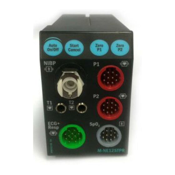
Table of contents 6.1.12 M-NE12STPR rev. 00, M-NE12STR rev. 00, M-NE12TPR rev. 00...........72 6.1.13 M-NE12STPR rev. 01........................72 6.1.14 Front panel stickers ........................73 6.1.15 Front panel stickers for S/5 modules...................74 Earlier Revisions APPENDIX A Service Check Form TABLE OF FIGURES Figure 1 S/5 NE12STPR Module, M-NE12STPR ................1 Figure 2 Absorption of infrared light in the finger probe parts layout and schematic diagram....9... - Page 6 Datex-Ohmeda S/5 monitors This page intentionally left blank. Document No. 800 1008-2...
-
Page 7: Introduction
The S/5 M-ESTPR/-ESTR/-ETPR and S/5 M-NE12STPR/-NE12STR/-NE12TPR/-NESTPR/- NESTR/-NETPR are double width modules designed for use with S/5 monitors. The modules provide general hemodynamic parameters. Later in this manual modules can be called w/o system name S/5. -
Page 8: Specifications
Datex-Ohmeda S/5 monitors SPECIFICATIONS 1.1 General specifications Module size 75 × 180 × 112 mm W × D × H 3.0 × 7.1 × 4.4 in Operation temperature 10...40 °C / 50...104 °F @ M-ESTPR/-ETPR/-ESTR Module weight 0.6 kg / 1.3 lbs... -
Page 9: Ecg
S/5 Hemodynamic modules 1.2.2 ECG Lead selection @ 12-lead ECG I, II, III, aVR, aVL, aVF, V1, V2, V3, V4, V5, V6 Lead selection @ other modules I, II, III, aVR, aVL, aVF, V Sweep speeds 12.5, 25, 50 mm/sec DISPLAY FILTER Diagnostic @ 12-lead ECG 0.05...150 Hz... -
Page 10: Temperature
Datex-Ohmeda S/5 monitors Adjustable pulse beep volume. PLETH WAVEFORM Scales 2, 5, 10, 20, 50 mod%, Auto Start up scale is 20 mod% if AUTO is not selected to be the default setting. 1.2.4 Temperature Measurement range 10...45 °C (50...113 °F) (In rev. -
Page 11: Technical Specifications
S/5 Hemodynamic modules 1.3 Technical specifications 1.3.1 NIBP Deflation rate, PR dep. 5...13 mmHg/s Inflation time 20...185 mmHg, 1...5 s Automatic software control, max. inflation pressure adult 280 ±10 mmHg child 200 ±10 mmHg infant 150 ±10 mmHg Over pressure limit, stops measurement after 2 seconds adult 320 mmHg child... -
Page 12: Pulse Oximetry
Datex-Ohmeda S/5 monitors 1.3.3 Pulse oximetry Protection against electrical shock Type BF defibrillation proof 1.3.4 Temperature Measurement accuracy ±0.1 °C (25.0...45.0 °C) ±0.2 °C (10.0...24.9 °C) Protection against electrical shock Type CF defibrillation proof NOTE: The accuracy of the measurement may be different from the specified, depending on transducer/probe used. -
Page 13: Functional Description
S/5 Hemodynamic modules FUNCTIONAL DESCRIPTION 2.1 Measurement principle 2.1.1 NIBP NIBP (Non-Invasive Blood Pressure) is an indirect method for measuring blood pressure. The NIBP measurement is performed according to the oscillometric measuring principle. The cuff is inflated with a pressure slightly higher than the presumed systolic pressure, and deflated at a speed based on the patient’s pulse, collecting data from the oscillations caused by the pulsating artery. - Page 14 The oxygen saturation percentage SpO measured by Datex-Ohmeda module is calibrated against the functional saturation SaO func. The advantage of this method is that the accuracy of SpO...
-
Page 15: Temperature
S/5 Hemodynamic modules Intensity of transmitted I max (DC-component) light I max AC-component I min Variable absorption Transmitted due to pulse added light volume of arterial blood Arterial blood Venous blood Tissue Time No pulsation Pulsatile blood Incident light SpO sensor connector SpO sensor cable Emitter IRED... -
Page 16: Invasive Blood Pressure
• across it. In Datex-Ohmeda modules the two methods are combined in a form of a voltage divider. The NTC- resistor is connected in series with a normal resistor and a constant voltage is applied across them. The temperature dependent voltage can be detected at the junction of the resistors, thus producing the temperature signal from the patient. -
Page 17: M-Ne12Stpr/-Ne12Str/-Ne12Tpr/-Nestpr/-Nestr/-Netpr Modules
S/5 Hemodynamic modules boards, attached to the front panel of the module. The front panel has six connectors and four keys. The connectors are two for temperature measurement, two for invasive blood pressure measurement, one for ECG, and one for SpO measurement. -
Page 18: Nibp Board
Datex-Ohmeda S/5 monitors In M-NETPR module, there are two small boards, the 2P input board and the ECG input board, attached to the front panel of the module. The front panel has six connectors and four keys. The connectors are two for temperature measurement, two for invasive blood pressure measurement, one for ECG, and one for NIBP. - Page 19 S/5 Hemodynamic modules Signal processing Two signals from the pressure transducers are amplified and sent to A/D converter. After the converter, digitized signals are sent to microprocessor for data processing. Before the converter, one of the signals is used to adjust the offset to the pressure safety level. The NIBP board is controlled with 80C51FA microprocessor at 16 MHz oscillator frequency.
-
Page 20: Ecg Board In 3-And 5-Lead Measurement
Datex-Ohmeda S/5 monitors 2.2.4 ECG board in 3-and 5-lead measurement Patient signals are connected to overload protection circuits (resistors and gas-filled surge arresters) and analog switches to instrumentation amplifiers. Then the signals are amplified by 480 and limited by slew rate. Then they are A/D-converted, analyzed and transferred to module bus in digital form. - Page 21 S/5 Hemodynamic modules Lower frequency is determined by high pass (HP) filter 0.5 Hz (monitor bandwidth) or 0.05 Hz (diagnostic or ST- bandwidth). Respiration section 3-lead cable The analog switches control the current supply source of the impedance respiration measurement, and the lead selection for the 3-lead cable can be seen from the following table: Table 2 Lead selection and coding for the 3-lead cable...
-
Page 22: Ecg Board In 12-Lead Measurement
Datex-Ohmeda S/5 monitors Isolated section The patient isolation of ECG is 5 kV. NOTE: The isolation has been changed from the earlier revisions. WARNING Do not touch battery operated monitor during defibrillation procedure. See the “Isolated section” in STP board description. - Page 23 S/5 Hemodynamic modules Front panel connector and ECG input board The connector for the 12-lead ECG cable is a green 12 pin Nicolay type connector. 3- or 5-lead cables with blue connector cannot be connected to this connector. The ECG input board contains high voltage resistors and a connector for ECG board.
-
Page 24: Ecg Filtering
Datex-Ohmeda S/5 monitors RS485 communication The communication to the CPU board of the monitor uses RS485 protocol. The RS485 driver circuits are optically isolated from the processor of the module. PWM signal is used for direct ECG signal. Direct ECG signal is available from the X2 connector of the UPI board or from the PT module. -
Page 25: Stp Board
S/5 Hemodynamic modules 2.2.7 STP board Patient connectors POX pre- TEMP PRESS amplifier measuring Front panel measuring unit keys unit gain control Temp AD Press AD AD-converter - 8 chn Pox AD - 12 bit Serial device communication Intensities µprocessor unit Power Non volatile Module... -
Page 26: Figure 9 Temperature Measurement Principle
Datex-Ohmeda S/5 monitors Temperature measurement unit Value of NTC-resistor in the probe depends on patient’s temperature. It is measured with the following principle. The temperature signal(s) is produced by voltage dividers, part of which is the patient probe (YSI 400-series thermistor). The output is amplified by the calibrated amplifier(s) whose offset voltage makes its output spread on both sides of zero. -
Page 27: Figure 11 Pulse Oximetry Measurement Block Diagram
S/5 Hemodynamic modules Pulse oximetry measurement section I=5-350mA IRed LED intensity adjustment LED driving circuit Red LED intensity Level of LED current adjustment measurement and feedback circuit Level of LED current indication (to CPU) Probe IR DC level G =1/4096-1 G = 275 IRed AC signal G =16... -
Page 28: Figure 12 Serial Communication And Opto Isolation Of M-Nestpr/-Ne12Stpr
Datex-Ohmeda S/5 monitors Red and infrared channel separation Red and infrared channels are separated from each other by switches. Operational amplifier functions as a buffer and after this infrared DC signal is sent to the processor. A capacitor separates AC signal from it and the AC signal is sent to the processor after amplification. There is a switch to choose the amplification constant. -
Page 29: Figure 13 Serial Communication And Opto Isolation Of M-Estpr
S/5 Hemodynamic modules STP Board Receive data Data RS485 Driver Send data NData Receive data Send data Opto isolation send/receive send/receive Reset Reset in RS485 Reset Driver NReset in ECG Board Receive data Receive dat Send data Send data Opto isolation send/receive send/receive Reset... -
Page 30: Connectors And Signals
Datex-Ohmeda S/5 monitors 2.3 Connectors and signals 2.3.1 Module bus connector Figure 14 Module bus connector (X1) pin layout Table 3 Module bus connector description Pin No Signal Note RESET_RS485 -15 VDC ∗∗ +15 VDIRTY +15 VDC ∗∗ -DATA_RS485 DATA_RS485 Ground &... -
Page 31: Front Panel Connectors
S/5 Hemodynamic modules 2.3.2 Front panel connectors Table 4 Front panel connectors 12-lead ECG connector Pin No Signal Pin No Signal Right arm electrode (R) Chest electrode (C3) Left arm electrode (L) Chest electrode (C4) Chest electrode (C5) Left leg electrode (F) Chest electrode (C6) Chest electrode (C1) Cable type... -
Page 32: Test Points On Boards
Datex-Ohmeda S/5 monitors 2.3.3 Test points on boards 12-lead ECG board 12-lead ECG board component side non floating 1 GND 6 +15 Vdirty 8 +5 V floating floating +5 Vanalog 10 GND 2 +5 Vdig. floating 1 -5 V 2 +2.5 V NIBP board There are test pad blocks on solder side. - Page 33 S/5 Hemodynamic modules ECG and STP board There are test pin blocks identical both on STP and ECG boards. Pins and voltages are as follows: ESTPR pin 1 +5 Vref pin 2 +5 V pin 3 +12 V pin 4 pin 5 -12 V pin 1...
-
Page 34: Service Procedures
Field service of the hemodynamic modules is limited to replacing faulty printed circuit boards or mechanical parts. Faulty printed circuit boards should be returned to Datex-Ohmeda for repair. Datex-Ohmeda is always available for service advice. Please provide the unit serial number, full type designation, and a detailed description of the fault. -
Page 35: Recommended Parts
S/5 Hemodynamic modules 3.2.2 Recommended parts Part Order No. Notes NIBP pump filter 57142 All modules Detach the module box by removing the two screws from the back of the module. Be careful with loose latch and spring pin for locking. Check internal parts: screws are tightened properly −... - Page 36 Datex-Ohmeda S/5 monitors Plug in the module. Check that it goes in smoothly and locks up properly Check that the module is recognized, i.e. all needed parameter information, except invasive blood pressure, starts to show on the screen. Preset ECG, Respiration, InvBP and SpO...
- Page 37 S/5 Hemodynamic modules Check that the power frequency value has been set according to the current mains power frequency. Change the setting by selecting Power Freq, if necessary. @ M-ESTPR, M-ETPR , M-ESTR, M-NESTPR, M-NETPR and M-NESTR modules: connect a 5- lead ECG cable to the module.
- Page 38 Datex-Ohmeda S/5 monitors Check that normal ECG waveform is shown, the HR -value is 160 (±5) and the ‘Pacer count’ -value is not increasing in the service menu. Check the lead selections by pressing the Lead key on the module (not available in NE12STPR/NESTPR type modules).
- Page 39 S/5 Hemodynamic modules Temperature measurement Enter the ESTP : STP service menu: Parameters - ESTP : STP Check that the ‘Timeouts’, ‘Bad checksums’ and ‘Bad c-s by mod’ values are not increasing faster than by 50 per second. Check also that the STP board memories have passed the internal memory test, i.e.
- Page 40 Datex-Ohmeda S/5 monitors ‘Probe’ show ON and the corresponding pressure waveform appears onto the screen. Perform the same check also for the InvBP channel P2. Calibrate the InvBP channels P1 and P2 according to the instructions in the chapter 3.4.4.
- Page 41 S/5 Hemodynamic modules Non Invasive Blood Pressure measurement Enter the NIBP module service menu: Parameters - NIBP Check that the ‘Timeouts’, ‘Bad checksums’ and ‘Bad c-s by mod’ values are not increasing faster than by 50 per second. Check also that the NIBP board memories have passed the internal memory test, i.e.
- Page 42 Datex-Ohmeda S/5 monitors Check the NIBP tubing system for leakages. Select Calibrations from the NIBP service menu. Connect the pressure manometer to the NIBP module cuff connector. Start the active leak test from the menu by pressing the ComWheel. The module pumps a pressure of about 265 mmHg and then the pump stops.
- Page 43 S/5 Hemodynamic modules Check the watchdog timer. Select Watchdog from the NIBP service menu. Check the watchdog timer in the adult mode. Activate the timer by highlighting Test ADULT and then pressing the ComWheel. Check that the time beside the text ‘Watchdog Interval’ starts to run.
- Page 44 Datex-Ohmeda S/5 monitors Connect the cuff onto your arm, highlight Start Ven.Stasis in the NIBP menu and press the ComWheel. Check the module identifies the cuff, i.e. the text ‘Adult’ appears into the NIBP digit field for a short moment.
-
Page 45: Disassembly And Reassembly
S/5 Hemodynamic modules 3.3 Disassembly and reassembly 3.3.1 M-ESTPR, M-ESTR, and M-ETPR modules Disassemble the M-ESTPR/-ESTR/-ETPR module in the following way. See the exploded view of the module in 6.1.1. Remove the two screws from the back of the module. Pull the module box slowly rearwards and detach it from the main body. -
Page 46: Adjustments And Calibrations
Datex-Ohmeda S/5 monitors 3.4 Adjustments and calibrations 3.4.1 Pressure safety level detection “OFFSET” Remove two screws at the rear of the module. Remove the module box. Connect first the service cable (e.g. a long Gas Interface Cable) to the module connector inside the monitor frame and then to the rear connector of the module. - Page 47 S/5 Hemodynamic modules Pump the following pressures to manometer and check the difference between the manometer and monitor pressure display: Table 5 NIBP calibration check pressures Pressure Max. error Example 0 mmHg ±9 mmHg (=zero offset) 100 mmHg 100 + zero offset ±2 mmHg 98 ±2 200 mmHg 200 + zero offset ±3 mmHg...
-
Page 48: Temperature Calibration
NOTE: For the temperature calibration, separate, accurate test plugs (25 °C and 45 °C) are needed. A test set of two plugs is available from Datex-Ohmeda, order code 884515. Calibrate temperature when measured test values deviate more than ±0.1 °C, and always after STP board replacement. -
Page 49: Troubleshooting
S/5 Hemodynamic modules TROUBLESHOOTING 4.1 Troubleshooting charts See also the User’s Reference Manual for more troubleshooting procedures. 4.1.1 NIBP TROUBLE CAUSE TREATMENT No NIBP value displayed NIBP not selected on screen. Check monitor setup. NIBP menu fading No M-NE(12)STPR module, module Plug in the module. - Page 50 Datex-Ohmeda S/5 monitors TROUBLE CAUSE TREATMENT Cuff loose-message 1. Hose and/or cuff not connected. 1. Connect the hose and the cuff. 2. Hose and cuff connected. Reasons: cuff loosely wrapped tighten the cuff − − leakage in cuff or hose replace cuff/hose −...
- Page 51 S/5 Hemodynamic modules TROUBLE CAUSE TREATMENT Cuff occlusion-message 1. Cuff and/or hose occluded. Reason: cuff tube kinked straighten tube − − tube inside module kinked straighten tube − − occlusion inside/outside remove occlusion − − module 2. Cuff, hose, and tubes OK. Reason: fault in pressure transducer replace the NIBP board...
-
Page 52: Nibp Error Code Explanation
Datex-Ohmeda S/5 monitors 4.1.2 NIBP error code explanation Code Explanation Treatment RAM failure; memory failure Change NIBP board. ROM checksum error; memory failure Change NIBP board. +15 V failure Check short circuits. Change NIBP board. -15 V failure Check short circuits. Change NIBP board. -
Page 53: Ecg
S/5 Hemodynamic modules 4.1.3 ECG TROUBLE CAUSE TREATMENT HR numerical display No heart rate available. If no ECG waveform, check LEADS OFF shows ‘---’ message and connect the leads. If ECG waveform exists, check heart rate source e.g. in the ECG Setup menu behind ECG key. -
Page 54: Temperature
Datex-Ohmeda S/5 monitors TROUBLE CAUSE TREATMENT 2. Finger is too thin or thick. 2. Try other fingers, or other probe types. Weak signal artifacts Poor perfusion. Try another place. Movement artifacts. Shivering. Message ‘NO PULSE’ Pulse search > 20 sec. and low Try other fingers. -
Page 55: Invasive Blood Pressure
S/5 Hemodynamic modules 4.1.6 Invasive blood pressure TROUBLE CAUSE TREATMENT Abnormally low pressure Transducer wrongly positioned. Check mid-heart level and reposition transducer. No pressure Defective transducer. Check transducer. No pressure module plugged in. Check the module. No waveform selected on screen. Check selected pressure waveforms by pressing Monitor Setup key and selecting modify waveforms. -
Page 56: Impedance Respiration
Datex-Ohmeda S/5 monitors TROUBLE CAUSE TREATMENT Out of range Measured pressure is beyond the The waveform hits the top and the internal measurement range of numeric display not shown. Check the module. transducer and its level. Zero the channel. 4.1.7 Impedance respiration... -
Page 57: Troubleshooting Flowcharts
S/5 Hemodynamic modules 4.2 Troubleshooting flowcharts 4.2.1 M-NE12STPR and M-NESTPR module troubleshooting START Possible fault in NIBP module. Remove all Insert NIBP module modules from and turn power on. Monitor Frame. Replace NIBP module. Does fault Fault not in still appear? NIBP module. -
Page 58: M-Estpr, M-Estr, And M-Etpr Module Troubleshooting
Datex-Ohmeda S/5 monitors 4.2.2 M-ESTPR, M-ESTR, and M-ETPR module troubleshooting Possibly faulty ESTPR module Check module configuration in Service menu (ESTPR/STP/Calibrations) Is it Select the correct correct? configuration Remove all modules from the frame Insert ESTPR module and turn power on... -
Page 59: Service Menu
S/5 Hemodynamic modules SERVICE MENU Monitor Setup Press the key. Select Install/Service (password 16-4-34). Select Service (password 26-23-8). Select Parameters - NIBP. NOTE: Parameter values in Service Data fields are for reference only on this chapter. Document No. 800 1008-2... -
Page 60: Nibp Service Menu
Datex-Ohmeda S/5 monitors 5.1 NIBP service menu Service Data Pressure shows measured pressure multiplied by 10. Zero shows pressure at auto zeroing multiplied by 10 and changes between +20 and -20 mmHg. Absolute pressure is the sum of Pressure and Zero. -
Page 61: Nibp Demo Menu
S/5 Hemodynamic modules EEPROM indicates if the values stored in the permanent memory are valid. The state is either OK, Fail or ? (module not in place or a communication error). 5.1.1 NIBP demo menu A service menu for demonstrating the oscillometric method of NIBP measurement. The menu shows the realtime pressure signals that are measured from the NIBP cuff. -
Page 62: Nibp Calibration Menu
Datex-Ohmeda S/5 monitors 5.1.2 NIBP calibration menu Active Leak Test Wrap an adult cuff around a pipe and connect the cuff to the module. Select the active leak test (ON). The module automatically pumps a pressure of 260 mmHg into the cuff. Wait for several seconds until the pressure stabilizes. -
Page 63: Nibp Safety Valve Menu
S/5 Hemodynamic modules Connect an external mercury manometer with pump to module through the both tubes of the hose. Pump up to about 200 mmHg pressure (range of 150 to 300 mmHg allowed) according to the manometer. Verify that both pressure values in the prompt field match the manometer reading. -
Page 64: Nibp Pulse Valve Menu
Datex-Ohmeda S/5 monitors 5.1.4 NIBP pulse valve menu Start Test Start test is for starting and Stop test is for stopping the test. Set Valve Set Valve lets you adjust the opening of the pulse valve. Pulse Valve Data See NIBP Service menu in chapter for information on general items Pressure, Zero, Protect handle, Calibr. -
Page 65: Nibp Buttons/Leds Menu
S/5 Hemodynamic modules 5.1.5 NIBP buttons/leds menu The selections Auto ON/OFF, Manual ON/OFF, STAT ON/OFF, and Measur. ON/OFF have no effect on the module. Buttons/Leds Data See NIBP Service menu in chapter for information on general items Pressure, Zero, Protect handle, Calibr. -
Page 66: Nibp Pneumatics Menu
Datex-Ohmeda S/5 monitors 5.1.6 NIBP pneumatics menu Start Pump/Stop Pump A manual control for the pump. The selection changes to Stop Pump when the pump turns on. Open Exh1/Close Exh1 A manual control for the exhaust valve 1. The selection changes to Close Exh1 when the valve is opened. -
Page 67: Nibp Watchdog Menu
S/5 Hemodynamic modules changes from negative to positive value (at about 5 mmHg) a beep is heard. This is the watchdog threshold pressure. Beyond this pressure the watchdog is active and cut pressures at about 2 min. (adult). 5.1.7 NIBP watchdog menu Test ADULT Test ADULT is to test watchdog timer in adult mode (120 to 140 seconds). -
Page 68: Ecg Service Menu
Datex-Ohmeda S/5 monitors 5.2 ECG service menu Power freq Set power frequency; 50 Hz/60 Hz. Filter low Set filter low frequency; 0.05 Hz/0.5 Hz. Filter high Set filter high frequency; 30 Hz (40 Hz if power freq is 60 Hz) /100 Hz or 150 Hz @ NE12STPR. - Page 69 S/5 Hemodynamic modules Timeouts is a cumulative number that indicates how many times the module has not responded to the monitor’s inquiry. Bad checksums is a cumulative number that indicates how many times communication from the module to monitor broke down. Bad c-s by mod is a cumulative number that indicates how many communication errors the module has detected.
-
Page 70: Ecg Setup Menu
Datex-Ohmeda S/5 monitors 5.2.1 ECG setup menu Filter Filters the ECG signal high frequency noise and slow respiratory artefacts. Monit (monitor) filter is used in routine monitoring. It effectively filters the artefacts caused by the electrosurgery unit and respiration. Diagn (diagnostic) filter is used if more accurate information of the waveform is needed (e.g., of P- wave or AV block). -
Page 71: Stp Service Menu
S/5 Hemodynamic modules 5.3 STP service menu Record Data Record Data prints out the shown service data and board information (id, serial number and sw id) onto the recorder module, M-REC. Temp Test Temp Test activates the automatic temperature test for the temperature channels T1 and T2. The result from the test is shown in the service data field. - Page 72 Datex-Ohmeda S/5 monitors DC gain shows the gain of DC signal adjusted by the module. IDC is the value of infrared signal. RDC is the dc value of red signal. AC gain is the gain of infrared and red ac signals. AC gain values can be 1 or 0. Value 1 means high ac gain and 0 means low gain.
-
Page 73: Stp Calibration Menu
S/5 Hemodynamic modules 5.3.1 STP calibration menu Protection Protection for the configuration and temperature calibrations can be set ON and OFF only when protect button at the bottom of the module is pressed. Set Config The module configuration should be set according to the module type. The setting is possible only when the protection is set OFF. -
Page 74: Spare Parts
Datex-Ohmeda S/5 monitors SPARE PARTS 6.1 Spare parts list NOTE: Only changed part numbers are listed under later revisions. To find the desired part: check first the list of the revision that corresponds your device. If the part is not listed there, check the previous revision, etc. -
Page 75: M-Estp Rev. 02, M-Etp Rev. 01, M-Est Rev. 01
S/5 Hemodynamic modules 6.1.2 M-ESTP rev. 02, M-ETP rev. 01, M-EST rev. 01 Item Item description Order no. STP board, M-ESTP (rev. 02) *(882130) Use 882627, 884342 ECG board, M-ESTP (rev. 02) *(882025) Use 888957, 883806 Front panel unit, M-ESTP (rev. 02-03) 882127 Front panel unit, M-ETP (rev. -
Page 76: M-Estpr Rev. 01, M-Etpr Rev. 01, M-Estr Rev. 01
Datex-Ohmeda S/5 monitors 6.1.6 M-ESTPR rev. 01, M-ETPR rev. 01, M-ESTR rev. 01 Item Item description Order no. Membrane keypad 879374 Module box (wide) 886168 Spring pin 879182 Latch 879181 Cross recess screw M3x8 black 616215 STP board, M-ESTP (rev. 03-05), M-P (rev. 02) *882627 ECG/RESP board, M-ESTPR (rev. -
Page 77: M-Nestpr Rev. 00, M-Netpr Rev. 00, M-Nestr Rev. 00
S/5 Hemodynamic modules 6.1.10 M-NESTPR rev. 00, M-NETPR rev. 00, M-NESTR rev. 00 Item Item description Order no. Item Item description Order no. Module box (wide) 886168 T input connectors *887152 Spring pin 879182 ECG input board, M-NESTPR (rev. 00) 889985 Latch 879181... -
Page 78: M-Nestpr Rev. 01, M-Netpr Rev. 01, M-Nestr Rev. 01
Datex-Ohmeda S/5 monitors 6.1.11 M-NESTPR rev. 01, M-NETPR rev. 01, M-NESTR rev. 01 Item Item description Order no. STP board, M-NESTPR (rev. 01) 8002574 NOTE: The STP board 8002574 includes the STP software 8000717. 6.1.12 M-NE12STPR rev. 00, M-NE12STR rev. 00, M-NE12TPR rev. 00... -
Page 79: Front Panel Stickers
S/5 Hemodynamic modules 6.1.14 Front panel stickers Front panel stickers that are related to the Compact Module type and adaptation: Adaptation codes: DA=Danish, DE=German, EN=English, ES=Spanish, FI=Finnish, FR=French, IT=Italian, JA=Japanese, NL=Dutch, NO=Norwegian, PT=Portuguese, SV=Swedish Item no. 10 or 29 M-ESTP M-ETP M-EST Adaptation... -
Page 80: Front Panel Stickers For S/5 Modules
Datex-Ohmeda S/5 monitors M-NESTPR M-NETPR M-NESTR Adaptation (rev. 00) (rev. 00) (rev. 00) Order No. Order No. Order No. 892204 892206 892205 891166 891678 891671 889264 891457 891456 891171 891681 891674 891170 891683 891676 891167 891679 891672 891172 891682 891675... - Page 81 898430 8000380 898459 898422 898485 898451 898428 898491 898457 898425 898488 898454 898427 898490 898456 S/5 M-NE12STPR S/5 M-NE12STR S/5 M-NE12TPR Adaptation (rev. 01) (rev. 01) (rev. 01) Order No. Order No. Order No. 898442 898470 898481 898433 898461 898472...
-
Page 82: Earlier Revisions
Datex-Ohmeda S/5 monitors EARLIER REVISIONS For service information on the earlier revisions, please refer to: Module revision Manual Note! ESTP Module revision 01 Service Manual p/n 880850 ETP Module revision 00 Service Manual p/n 880850 ESTP Module revision 02 Service Manual p/n 882580... -
Page 83: Service Check Form
APPENDIX A, Service check form, S/5 Hemodynamic modules APPENDIX A Document No. 800 1008-2... - Page 84 Datex-Ohmeda S/5 monitors This page intentionally left blank. Document No. 800 1008-2...
- Page 85 APPENDIX A, Service check form, S/5 Hemodynamic modules SERVICE CHECK FORM DATEX-OHMEDA HEMODYNAMIC MODULES Customer Service Service engineer Date OK = Test OK N.A. = Test not applicable Fail = Test Failed All modules N.A. Fail N.A. Fail 1. Internal parts 2.
- Page 86 Datex-Ohmeda S/5 monitors RESP measurement N.A. Fail N.A. Fail 13. RESP measurement 14. Test with patient recognition simulator Notes TEMP measurement N.A. Fail N.A. Fail 15. Communication and 16. Temperature probe memories detection 17. Calibration check 18. Temp test -function 19.
- Page 87 APPENDIX A, Service Check Form,S/5 Hemodynamic Modules NIBP measurement N.A. Fail N.A. Fail 26. Communication and 27. Membrane keys memories 28. Pump and valves 29. Leak test ≤ 5 mmHg/min 30. Calibration check Measured B1 Measured B2 Allowed range 0 mmHg ±...
- Page 88 Datex-Ohmeda S/5 monitors All modules N.A. Fail N.A. Fail 38. Electrical safety check 39. Functioning after electrical safety check 40. Final cleaning Notes Notes Used Spare Parts Signature A 4 (4) Document No. 8001008-2...
Need help?
Do you have a question about the S/5 M-NE12STPR and is the answer not in the manual?
Questions and answers