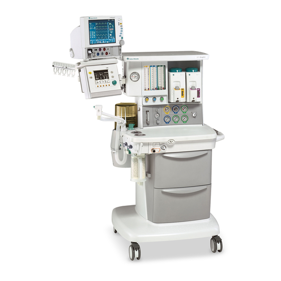
Datex-Ohmeda Aespire S/5 Technical Reference Manual
Anesthesia machine
Hide thumbs
Also See for Aespire S/5:
- User's reference manual (80 pages) ,
- User's reference manual (112 pages) ,
- Technical reference manual (300 pages)
Table of Contents
Advertisement
Quick Links
Advertisement
Chapters
Table of Contents
Troubleshooting

Related Manuals for Datex-Ohmeda Aespire S/5


Summary of Contents for Datex-Ohmeda Aespire S/5
- Page 1 S/5 Aespire Anesthesia Machine Technical Reference Manual...
- Page 2 S/5 Aespire Datex-Ohmeda products have unit serial numbers with coded logic which indicates a product group code, the year of manufacture and a sequential unit number for identification. AAA F 12345 This alpha character indicates the year of product manufacture and when the serial number was assigned;...
- Page 3 S/5 ProTIVA anesthesia machine This document is not to be reproduced in any manner, nor are the contents to be disclosed to anyone, without the express authorization of the product service department, Datex-Ohmeda, Ohmeda Drive, PO Box 7550, Madison, Wisconsin, 53707.
-
Page 4: Important
The information contained in this service manual pertains only to those models of products which are marketed by Datex-Ohmeda as of the effective date of this manual or the latest revision thereof. This service manual was prepared for exclusive use by Datex-Ohmeda service personnel in light of their training and experience as well as the availability to them of parts, proper tools and test equipment. -
Page 5: Table Of Contents
Table of Contents Important ..............ii Technical Competence . - Page 6 S/5 Aespire 3 Checkout Procedure 3.1 Inspect the system ............3-2 3.2 Pipeline and cylinder tests .
- Page 7 Table of Contents 4.9 Service the flowmeter module ..........4-13 4.9.1 Remove front flowmeter panel shield .
- Page 8 S/5 Aespire 4.21 Replace the display arm or display cables ........4-48 4.21.1 Cable tie installation .
- Page 9 Table of Contents 8 Illustrated Parts 8.1 Service tools — Anesthesia machine ......... .8-3 8.1.1 Test Devices .
- Page 10 S/5 Aespire 8.22 Breathing System ............8-37 8.22.1 APL Valve .
-
Page 11: Introduction
Introduction In this section This section provides a general overview of the S/5 Aespire Anesthesia Machine. 1.1 What this manual includes ..........1-2 1.2 Standard service procedures . -
Page 12: What This Manual Includes
S/5 Aespire 1.1 What this manual includes Anesthesia Machine This manual covers the service information for the S/5 Aespire line of anesthesia machines. It covers the following components: • gas delivery components, • breathing system components, • frame component (except those strictly associated with a specific ventilator), •... -
Page 13: What Is An S/5 Aespire
1 Introduction 1.3 What is an S/5 Aespire The S/5 Aespire is a compact, integrated and intuitive anesthesia delivery system. The ventilator portion provides mechanical ventilation to a patient during surgery as well as monitoring and displaying various patient parameters. The system uses a microprocessor-controlled ventilator with internal monitors, electronic PEEP, Volume Mode, and other optional features. -
Page 14: Configuration Options
S/5 Aespire 1.4 Configuration options 1.4.1 Standard The standard configuration includes the following items. Items marked with an asterisk (*) are not included in the Aespire 100 configuration machine. • 7100 Ventilator • Advanced Breathing System (ABS) • Auxiliary Common Gas Outlet (ACGO) •... - Page 15 1 Introduction 1. Auxiliary common gas outlet (ACGO) switch 2. ACGO 3. Inspiratory check valve 4. Inspiratory flow sensor or flow port adapter 5. Canister (carbon dioxide absorbent) 6. Canister release 7. Expiratory flow sensor or flow port adapter 8. Leak test plug 9.
- Page 16 S/5 Aespire 1. ABS (Advanced Breathing System) 2. Flow controls 3. Ventilator Display/Control Module 4. Dovetail rails 5. Vaporizer 6. Pipeline pressure gauge(s) (upper row) 7. System switch 8. Cylinder pressure gauge(s) (lower row) 9. O Flush 10. Auxiliary O flowmeter 11.
- Page 17 1 Introduction AC Inlet for Aespire 100 machine 1. Circuit Breaker for Electrical Outlets* 2. Electrical Outlets* 3. Pipeline Connection(s) 4. Cylinder Supplies 5. System Circuit Breaker (A A A A C C C C I I I I n n n n l l l l e e e e t t t t f f f f u u u u s s s s e e e e s s s s f f f f o o o o r r r r A A A A e e e e s s s s p p p p i i i i r r r r e e e e 1 1 1 1 0 0 0 0 0 0 0 0 m m m m a a a a c c c c h h h h i i i i n n n n e e e e ) 6.
- Page 18 S/5 Aespire 1. Ventilator/Monitoring display 2. Syringe pumps (3) 3. fm controller 4. fm computer 5. fm segment Figure 1-4 • S/5 ProTIVA with a typical B Braun fluid manager (fm) system 07/04 1009-0356-000...
-
Page 19: Symbols Used In The Manual Or On The Equipment
Cautions tell about a condition that can cause damage to the equipment. Read and follow all warnings and cautions. Other symbols replace words on the equipment or in Datex-Ohmeda manuals. No one device or manual uses all of the symbols. These symbols include:... - Page 20 S/5 Aespire Plus, positive polarity Movement in one direction Minus, negative polarity Movement in two directions Variability Read top of float Variability in steps Vacuum inlet This way up Suction bottle outlet Lamp, lighting, illumination Cylinder Lock Isolation transformer Unlock Linkage system Close drain Risk of Explosion.
- Page 21 1 Introduction Alarm silence touch key Volume alarms On/Off touch key End case touch key Menu touch key Circle breathing circuit module Bain/Mapleson D breathing circuit module The primary regulator is set to pressure The primary regulator is set to pressure <...
- Page 22 Notes 1-12 07/04 1009-0356-000...
-
Page 23: Theory Of Operation
Theory of Operation In this section 2.1 Theory overview ............2-2 2.2 Gas flow through the anesthesia machine . -
Page 24: Theory Overview
S/5 Aespire 2.1 Theory overview This section describes: • The flow of gas through the anesthesia machine. • The flow of gas through the breathing system. • Electrical signals between the anesthesia machine, including the breathing system, and the ventilator. 2.2 Gas flow through the anesthesia machine 2.2.1 Overview Refer to Figure 2-1. - Page 25 2 Theory of Operation Air and N O flow Pipeline or regulated cylinder pressure supplies Air directly to the ventilator (7b for Air drive gas) and the venturi suction (21b for Air drive gas) supply connection. When the system switch (8) is On, air flows to the rest of the system. A secondary regulator (18) supplies the Air flow control valve (19).
- Page 26 S/5 Aespire Key to Numbered Components 1. Pipeline pressure gauge 2. Pipeline inlet 3. Cylinder pressure gauge 4. Cylinder inlet (maximum of 3 cylinders) 5. Primary regulator (cylinder pressure) 6. High-pressure relief valve (758 kPa / 110 psi)* 7. Supply connections for the ventilator a.
- Page 27 2 Theory of Operation Link 25 Link 25 A. Cylinder Supplies B. Pneumatic Manifold C. Flowmeter Head D. Vaporizer Manifold E. ACGO Select Switch Figure 2-1 • Pneumatic circuit 1009-0356-000 07/04...
-
Page 28: Physical Connections
S/5 Aespire 2.2.2 Physical Figure 2-2 shows the physical path that the gas takes. connections Vent Drive Figure 2-2 • Typical tubing connections - pictorial 07/04 1009-0356-000... -
Page 29: Suction Regulators
2 Theory of Operation 2.2.3 Suction regulators Pipeline vacuum The suction regulator (shown in Figure 2-2) uses an external vacuum source. Venturi Drive vacuum The suction regulator (shown in Figure 2-3) uses an internal, venturi derived vacuum source. Drive gas (internally plumbed Air or O ) enters the Venturi Module (VM) at the drive port (A). -
Page 30: System Switch
S/5 Aespire 2.2.4 System switch The system switch has two positions: On and Standby. In the Standby position The switch: • Turns off the ventilator (electrical). • Stops O and Air to the flowhead (pneumatic). • Without O pressure, the N O balance regulator stops N In the On position The switch:... -
Page 31: Flow Control
2 Theory of Operation 2.2.5 Flow control Needle valves (one for each gas) adjust gas flows. Clockwise rotation decreases flow. Counterclockwise increases flow. Mechanical stops set minimum flows for all gases. The link system sets the maximum ratio of N O to w w w w WARNING The Link 25 Proportioning System sets a minimum O... - Page 32 S/5 Aespire Higher concentrations of O are possible when the link system is not engaged: either by reducing the N O flow below the point of engagement or by increasing O flow above the point of engagement. When the N O flow is below the point of engagement, increasing the N O flow turns the O...
-
Page 33: Flow Through The Breathing System
2 Theory of Operation 2.3 Flow through the breathing system 2.3.1 Overview of flow This section looks at three types of flow paths. paths • Ventilation paths: How gas flows from the drive source (bag or bellows) to and from the patient. •... -
Page 34: Manual Ventilation
S/5 Aespire 2.3.2 Manual ventilation Manual inspiration The Bag/Vent switch closes the ventilator path (B)..(Figure 2-4) Gas flows from the bag (1), through the absorber (2), into the breathing circuit module, and through a unidirectional valve (inspiratory check valve) to the patient (3). - Page 35 2 Theory of Operation Manual expiration The Bag/Vent switch keeps the ventilator path closed (B). (Figure 2-5) Gas flows from the patient (4), through a unidirectional valve (expiratory check valve), and into the bag (5). During exhalation, fresh gas flows backwards through the absorber (FG) into the expiratory limb, downstream of the expiratory check valve.
- Page 36 S/5 Aespire APL Valve The APL valve sets a pressure limit for manual ventilation. (Figure 2-6) As you turn the APL knob, it puts more or less force on the APL disc and seat (D/S). If the circuit pressure is too high (6), the disc and seat inside the diaphragm opens and vents gas to the scavenging system (7).
-
Page 37: Mechanical Ventilation
2 Theory of Operation 2.3.3 Mechanical ventilation Mechanical inspiration The Bag/Vent switch closes the manual path (V). Pilot pressure (P) closes the (Figure 2-7) exhalation valve. Drive gas (D) pushes down on the bellows. Gas flows from the bellows (1), through the absorber (2), and through a unidirectional valve (inspiratory check valve) to the patient (3). - Page 38 S/5 Aespire Mechanical expiration Drive-gas flow stops and the exhalation valve opens. Exhaled gas flows from (Figure 2-8) the patient (4), through a unidirectional valve (expiratory check valve) and into the bellows (5). Residual drive gas (D) flows out of the bellows to the scavenging system (6).
- Page 39 2 Theory of Operation Pop-off valve(Figure 2-9) The pop-off valve limits the pressure inside the bellows to 2.5 cm H O above the drive gas pressure. This normally occurs when the bellows reaches the top of the housing at the end of exhalation. Excess gas (7) vents to the scavenging system (6) through the pop-off valve and the exhalation valve.
-
Page 40: Fresh Gas And O 2 Flush Flow
S/5 Aespire 2.3.4 Fresh gas and O flush flow To ABS breathing system Fresh gas (1) flows from the vaporizer manifold outlet to the ACGO Selector (Figure 2-10) Switch. With the ACGO Selector Switch in the ABS position, fresh gas flow is channeled to the breathing system. - Page 41 2 Theory of Operation Auxiliary Common Gas Fresh gas (1) flows from the vaporizer manifold outlet to the ACGO Selector Switch. Outlet(Figure 2-11) With the ACGO Selector Switch in the ACGO position, fresh gas flow is channeled to the ACGO outlet. At the ACGO outlet, a small sample is diverted to the O Sensor in the ABS for O monitoring.
- Page 42 Notes 2-20 07/04 1009-0356-000...
-
Page 43: Checkout Procedure
Checkout Procedure In this section 3.1 Inspect the system ............3-2 3.2 Pipeline and cylinder tests . -
Page 44: Inspect The System
S/5 Aespire 3.1 Inspect the system Make sure that: • The equipment is not damaged. • All components are correctly attached. • Pipeline gas supplies are connected and the pressures are correct. • A supply of reserve O is provided and connected to the machine. •... -
Page 45: Pipeline And Cylinder Tests
3 Checkout Procedure 3.2 Pipeline and cylinder tests w w w w CAUTION To prevent damage: • Open the cylinder valves slowly. • Do not force the flow controls. If your system does not use cylinder supplies, do not do steps 2 and 3. 1. -
Page 46: Flow Control, Pressure Relief, O Supply Alarm, And Flush Flow Tests
S/5 Aespire 3.3 Flow control, pressure relief, O supply alarm, and flush flow tests If the system includes O monitoring, complete the flow control tests in Section 3.3.1, “With O monitoring”. If the system does not include O monitoring, complete the flow control tests in Section 3.3.2, “Without O monitoring”. - Page 47 3 Checkout Procedure Note: Allow the O monitor to stabilize. At the lower flows, the O monitor may take up to 90 seconds to stabilize. d. If you overshoot a setting, turn the O flow control clockwise until the O flow decreases to the previous setting before continuing the test. Set the N O flow (L/min) Measured O...
-
Page 48: Without O 2 Monitoring
S/5 Aespire 3.3.2 Without O monitoring w w w w WARNING The following procedure will test for any significant malfunction of the Link system but it will not confirm proper calibration. Periodic calibration procedures using an accurate and properly calibrated O monitor must be performed as recommended in the User’s Reference Manual, Part 2, section 3 User Maintenance. - Page 49 3 Checkout Procedure d. If you overshoot a setting, turn the O flow control clockwise until the O flow decreases to the previous setting before continuing the test. Set the N O flow control to The O flow must be (L/min) greater than (L/min):...
-
Page 50: Pressure Relief Tests
S/5 Aespire 3.3.3 Pressure relief To check the pressure relief valve (vaporizer manifold outlet). tests 1. Turn all flow controls fully clockwise (minimum flow). 2. Set the ACGO selector switch to ACGO. 3. Connect a gauge or a digital manometer to the ACGO outlet using the positive pressure leak test adapter. - Page 51 3 Checkout Procedure Without Ventilator: 1. Set the Bag/Vent switch to Bag. 2. Set the system switch to Standby. 3. Attach a patient circuit and plug the patient port. 4. Attach a 3-liter rebreathing bag on the bag arm or manual bag port (if a 3-liter bag is not available, use the time specified for a1-liter bag times the volume of the bag used).
-
Page 52: Vaporizer Back Pressure Test
S/5 Aespire 3.4 Vaporizer back pressure test w w w w WARNING Anesthetic agent vapor comes out of the common gas outlet during this test. Use a safe, approved procedure to remove and collect the agent. 1. Set up the gas scavenging system. a. -
Page 53: Low-Pressure Leak Test
3 Checkout Procedure 3.5 Low-pressure leak test Note Perform either the “Negative low-pressure leak test” or the “ISO or BSI standard low-pressure leak test. It is not necessary to perform both tests. w w w w WARNING Do not use a system with a low-pressure leak. Anesthetic gas will go into the atmosphere, not into the breathing circuit. -
Page 54: Iso Or Bsi Standard Low-Pressure Leak Test
S/5 Aespire 3.5.2 ISO or BSI standard low-pressure leak test w w w w CAUTION Do the positive pressure leak test at the ACGO outlet only. 1. Set the ACGO selector switch to ACGO. 2. Turn all flow controls fully clockwise (minimum flow). 3. - Page 55 3 Checkout Procedure 7. Open the O flow control and set a total flow of 0.4 L/min through the flowmeter on the test device. 8. Make sure that the pressure gauge on the test device reads zero and that all other flow controls are fully closed. 9.
-
Page 56: Alarm Tests
S/5 Aespire 3.6 Alarm tests 1. Connect a test lung to the patient connection. 2. Set the Bag/Vent switch to Vent. 3. Set the system switch to On. 4. Set the controls: • Ventilation Mode: Volume control (select from main menu) •... - Page 57 3 Checkout Procedure 11. Test the high airway pressure alarm: a. Set P to less than the peak airway pressure. limit b. Make sure that the high airway pressure alarm occurs. c. Set P to correct level. limit 12. Test the apnea and low airway pressure alarms: a.
-
Page 58: Breathing System Tests
S/5 Aespire 3.7 Breathing system tests w w w w WARNING Objects in the breathing system can stop gas flow to the patient. This can cause injury or death: • Do not use a test plug that is small enough to fall into the breathing system. - Page 59 3 Checkout Procedure Bag Circuit 6. Test the Bag circuit for leaks: a. Set the system switch to On. b. Set the Bag/Ventilator switch to Bag. c. Plug the Bag port (use your hand or the approved test plug). d. Close the APL valve (70 cm H e.
-
Page 60: Auxiliary O2 Flowmeter Tests
S/5 Aespire 3.8 Auxiliary O flowmeter tests 1. Open the O cylinder valve or connect an O pipeline. 2. Rotate the flow control clockwise (decrease) to shut off the flow. The ball should rest at the bottom of the flow tube and not move. 3. -
Page 61: Power Failure Test
3 Checkout Procedure 3.10 Power failure test 1. Connect the power cord to a mains outlet. The mains indicator on the display comes on when AC Power is connected. If the indicator is not on, the display assembly is not receiving AC power. •... - Page 62 Notes 3-20 07/04 1009-0356-000...
-
Page 63: Repair Procedures
Repair Procedures In this section This section covers the repair and replacement procedures for components of the Aespire anesthesia machine. 4.1 Servicing the ventilator ............4-3 4.2 How to bleed gas pressure from the machine . - Page 64 S/5 Aespire 4.10 Service vaporizer manifold parts ......... . . 4-26 4.10.1 Repair manifold port valve .
-
Page 65: Servicing The Ventilator
4 Repair Procedures WARNING To prevent fires: • Use lubricants approved for anesthesia or O equipment, such as Krytox. • Do not use lubricants that contain oil or grease; they burn or explode in high concentrations. • All covers used on the system must be made from antistatic (conductive) materials. -
Page 66: How To Bleed Gas Pressure From The Machine
S/5 Aespire 4.2 How to bleed gas pressure from the machine Before disconnecting pneumatic fittings, bleed all gas pressure from the machine. 1. Set the system switch to On. 2. Close all cylinder valves and disconnect all pipeline supplies from the source. N N N N o o o o t t t t e e e e : : : : If the machine includes N O, do not disconnect the O pipeline. -
Page 67: How To Remove The Tabletop
4 Repair Procedures 4.4 How to remove the tabletop The tabletop is held in place with five captive screws along the periphery of the pan assembly (accessed from below the rim of the tabletop). • One screw (A) is in a deep recess at the right-rear corner of the tabletop. •... -
Page 68: Replace Pipeline Inlet Filter
S/5 Aespire 4.5 Replace pipeline inlet filter 1. Remove the pipeline inlet fitting. 2. Pull the pipeline inlet filter out of the fitting. The o-ring should come out with the filter. 3. Install the new pipeline inlet filter in the pipeline inlet fitting. The new filter comes with an o-ring. -
Page 69: Change Drive Gas
4 Repair Procedures 4.6 Change drive gas CAUTION If you change the drive gas, you must also change the drive gas selection on the ventilator service setup screen. Refer to Section 4 of the ventilator Technical Reference manual. • If the drive gas selection and the actual drive gas do not agree, volumes will not be correct. -
Page 70: Service The Cylinder Supply Modules
S/5 Aespire 4.7 Service the cylinder supply modules w WARNING Be careful not to expose internal components to grease or oil (except Krytox or equivalent). 4.7.1 Tightening The cylinder pressure gauge is connected to the cylinder supply through a copper tube with fittings at both ends. -
Page 71: Replace Cylinder Inlet Filter
4 Repair Procedures 4.7.3 Replace 1. Open the cylinder yokes. cylinder inlet filter 2. Remove the inlet adapter from the cylinder yoke, using a 4 mm hex wrench. Note: A brass retaining ring keeps the filter inside the inlet adapter. 3. -
Page 72: Replace 3Rd-Gas Cylinder Supply Module
S/5 Aespire 4.7.5 Replace 1. Remove the lower rear cover (Section 4.3.2). 3rd-gas cylinder 2. Disconnect the high-pressure cylinder gauge fitting. supply module 3. Disconnect the output tube fitting. 4. Remove the three mounting screws and lockwashers. Outlet tube fitting Pressure gauge fitting 5. -
Page 73: Replace System Switch Assembly
4 Repair Procedures 4.8 Replace system switch assembly 1. Bleed all gas pressure from the machine (Section 4.2). 2. Ensure that all cylinder and pipeline gauges read zero before proceeding. 3. Remove the tabletop (Section 4.4). 4. Remove the gauge panel mounting screws and move the panel forward to access the system switch. - Page 74 S/5 Aespire 9. Install the replacement switch assembly: a. Loosen the two outside screws on the electrical module. b. Insert the wires in the electrical module and tighten the screws. c. Pull the wires on the electrical module to ensure that there is a good connection. d.
-
Page 75: Service The Flowmeter Module
4 Repair Procedures 4.9 Service the flowmeter module 4.9.1 Remove 1. Bleed all gas pressure from the machine (Section 4.2). front flowmeter 2. Ensure that all cylinder and pipeline gauges read zero before proceeding. panel shield 3. The flowmeter panel is held in place with two latching tabs at the right side. To remove the panel, release each latch by pushing it toward the center of the panel with a thin rod (3-mm hex wrench) through the access hole in the shroud. - Page 76 S/5 Aespire w w w w WARNING Floats are calibrated to a specific tube. Keep each float with its tube. Replace tube and floats together. Interchanging floats can cause incorrect readings. Disassemble the flowtube assemblies only when service is required. Excessive cleaning can remove the antistatic coating from inside the tube.
-
Page 77: Remove Complete Flowmeter Head
4 Repair Procedures 4.9.3 Remove 1. Remove the rear panel (Section 4.3). complete 2. Disconnect the tubing at the rear of each gas module. The following example is a flowmeter head back view of the flowmeter head. Fresh gas out O in Air in supply... -
Page 78: Replace Flowmeter Modules
S/5 Aespire 4.9.4 Replace 1. Remove the complete flowmeter head (Section 4.9.3). flowmeter 2. Refer to the following illustrations. Note that these illustrations show ANSI flowmeter modules module positions. The order is reversed in ISO machines. /Air modules /Air flowmeter modules are connected at the bottom with a long screw (A) and nut (B) that is recessed. - Page 79 4 Repair Procedures Single-tube flowhead The outlet fitting for a single-tube flowhead is not an integral component of the O flowmeter. The outlet fitting is a separate component that includes an o-ring seal and is held in place with two u-clips. Small Large U-Clip...
- Page 80 S/5 Aespire Remove g. The O and N O flowmeter modules are held together by a single screw. Remove the screw located on the side of the O flowmeter module. h. Hold the flowmeter modules with the flowtubes facing you. i.
- Page 81 4 Repair Procedures Sprocket/Chain Assembly 13. Install the N O knob. Snug one set screw to hold the knob in place. 14. Perform the link system calibration (Section 6.4). 15. Install the flowmeter panel shield. 16. Perform the checkout procedure (Section 3). 1009-0356-000 07/04 4-19...
-
Page 82: Replace Flowmeter Frame
S/5 Aespire 4.9.5 Replace 1. Remove the front flowmeter panel shield (Section 4.9.1). flowmeter frame 2. Remove the complete flowmeter head (Section 4.9.3). 3. Separate the flowmeter modules as required (Section 4.9.4). 4. Remove the flowtubes (Section 4.9.2). Keep all the parts for reassembly. 5. -
Page 83: Replace O
4 Repair Procedures 4.9.6 Replace O The O supply switch is located on the O flowmeter’s regulator module. supply switch 1. Remove the upper rear panel (Section 4.3). 2. Remove the two mounting screws from the O supply switch. Adjustment screw 4-mm hex 3. -
Page 84: Replace Secondary Regulator Manifold Or Balance Regulator Manifold
S/5 Aespire 4.9.8 Replace 1. Remove the front flowmeter panel shield (Section 4.9.1). secondary 2. Remove the complete flowmeter head (Section 4.9.3). regulator manifold 3. Separate the flowmeter modules (Section 4.9.4). or balance 4. Remove the flowmeter frame from the regulator manifold by removing the four regulator manifold screws at the rear of the regulator manifold (no need to remove flowtubes). -
Page 85: Replace O Or N O Needle Valves (On Machines With N O)
4 Repair Procedures 4.9.9 Replace O For machines without N O, refer to Section 4.9.10 for replacing the O needle valve. or N O needle 1. Bleed all gas pressure from the machine (Section 4.2). valves (on 2. Ensure that all cylinder and pipeline gauges read zero before proceeding. machines with 3. - Page 86 S/5 Aespire 15. After calibrating the needle valve, put the spacer the N O needle valve spindle. Spacer 16. Put the chain on the O knob/sprocket assembly and the N O sprocket. 17. Install the chain and sprockets on the needle valve spindles as an assembly. Do not tighten the set screws.
-
Page 87: Needle Valve On Machines
4 Repair Procedures 4.9.10 Replace an For machines with N O, refer to Section 4.9.9 for replacing the O needle valve. Air needle valve on 1. Bleed all gas pressure from the machine (Section 4.2). all machines or an 2. Ensure that all cylinder and pipeline gauges read zero before proceeding. needle valve on 3. -
Page 88: Service Vaporizer Manifold Parts
S/5 Aespire 4.10 Service vaporizer manifold parts 4.10.1 Repair 1. Set the system switch to Standby. manifold port 2. Remove the vaporizers from the vaporizer manifold. valve 3. Using a 14-mm wrench, carefully remove the valve nipple (threaded). 4. Disassemble as necessary to replace parts. The following illustration shows the parts. -
Page 89: Checkout Procedure For Manifold Port Valve
4 Repair Procedures 4.10.2 Checkout Use the Vaporizer Manifold Valve Test Tool to perform the checkout procedure for the manifold port valve. This tool and test procedure are intended for use only when the procedure for valve cartridge assembly is replaced. manifold port valve Note... -
Page 90: Replace Vaporizer Manifold Check Valve
S/5 Aespire 4.10.3 Replace 1. Set the system switch to Standby. vaporizer manifold 2. Remove the vaporizers from the vaporizer manifold. check valve 3. Remove the upper rear panel. 4. Disconnect the tubing from the valve block. 5. Remove the valve block. •... - Page 91 4 Repair Procedures Note The valve body, o-ring, and flapper do not come out with the block. They stay intact at the bottom of the vaporizer manifold. 6. Pull the flapper out of the valve body. O-ring Valve body Flapper Valve body O-ring Flapper...
-
Page 92: Replace Vaporizer Pressure Relief Valve
S/5 Aespire 4.10.4 Replace 1. Set the system switch to Standby. vaporizer pressure 2. Remove the vaporizers from the vaporizer manifold. relief valve 3. Remove the upper rear panel (Section 4.3). 4. Using a 13mm open ended wrench, remove the vaporizer pressure relief valve by turning counterclockwise. -
Page 93: Replace Vaporizer Manifold
4 Repair Procedures 4.10.5 Replace 1. Remove the upper rear panel (Section 4.3). vaporizer manifold 2. Remove the front flowmeter shield (Section 4.9.1). 3. Remove the right side panel (A). 4. From the front of the machine, remove the screw (B) at the right upright of the flowhead bezel. -
Page 94: Replace Acgo Selector Switch
S/5 Aespire 4.11 Replace ACGO selector switch Removal 1. Remove the tabletop (Section 4.4). 2. Clip the tie wraps ( ) from the outlet barb fittings at the side of the switch. 3. Disconnect the fresh gas ( ) and flush ( ) tubes at the back of the switch. - Page 95 4 Repair Procedures 5. Place the shroud over the knob and guide the assembly into the pan opening. 6. Ensure that the indicators on the shroud align with label on the pan and the alignment tab mates with the alignment hole in the pan. 7.
-
Page 96: Clean Or Replace Acgo Port Flapper Valve
S/5 Aespire 4.12 Clean or replace ACGO port flapper valve 1. Remove the tabletop (Section 4.4). 2. Remove the ACGO cap mounting screws. 3. Remove the cap. 4. Examine the flapper and disk for obstructions or debris. Clean with isopropyl alcohol if necessary; retest. 5. -
Page 97: Reconfigure Sample Gas Return Line
4 Repair Procedures 4.13 Reconfigure sample gas return line Sample gas return is directed to the scavenging system as a factory default. Perform the following to reroute the sample gas back to the breathing system. Refer to “Tubing” on page 9-8. 1. -
Page 98: Replace The Apl Valve
S/5 Aespire 4.14 Replace the APL valve 1. Remove the ABS breathing system. 2. The APL valve is held in place with a spring and a retainer (A) that snaps into a recess in the lower body of the APL valve. -
Page 99: Replace The Bag Support Arm
4 Repair Procedures 4.15 Replace the bag support arm 1. Remove the ABS breathing system from the machine. 2. From the underside of the casting, remove the two screws/ lockwashers (A) that hold the arm in place. • If either of the pins (see below) remain in the casting, remove them from the casting. -
Page 100: Servicing The Bag Support Arm
S/5 Aespire 4.15.1 Servicing Service parts for the bag support arm include the upper and lower assemblies. the bag support To replace either assembly: 1. Remove the bag support arm from the machine (Section 4.15). 2. To separate the upper assembly from the lower assembly, use a small (2.5-mm) pin punch from the bottom to drive the dowel pin up and... -
Page 101: Replace Friction Pad In Lower Bag Arm Assembly
4 Repair Procedures 4.15.2 Replace 1. Remove the ABS breathing system from the machine. friction pad in 2. Using an 8-mm socket, remove the lower bag arm nut (A), shoulder washer, and spring assembly from the lower assembly. 3. Lift the bag support arm off of the swivel post. -
Page 102: Replace Bag Port Housing
S/5 Aespire 4.15.3 Replace 1. Remove the bag support arm bag port housing cover (A) — screw and lockwasher from below. 2. Remove nut (B) to remove the release lever (C). 3. Remove the retaining ring (D). 4. Slide the bag port housing (E) off the end of the bag support arm. -
Page 103: Replace Auxiliary O
4 Repair Procedures 4.16 Replace auxiliary O flowmeter 1. Bleed all gas pressure from the machine (Section 4.2). 2. Ensure that all cylinder and pipeline gauges read zero before proceeding. 3. Remove the tabletop (Section 4.4). 4. Remove the adjustment knob from the flowmeter; pull forward. 5. -
Page 104: Replace The Suction Control Module
S/5 Aespire 4.17 Replace the suction control module The suction control module can be replaced by removing the front panel, along with the ABS and the tabletop, to gain access. Alternatively, if the situation warrants, the suction control module can be accessed by removing the rear panel. 4.17.1 Front panel 1. -
Page 105: Rear Panel Method
4 Repair Procedures 4.17.2 Rear panel 1. Lower the upper rear panel (Section 4.3). method 2. Disconnect the white (A) vacuum and black (B) suction fittings from the rear panel. Do not remove the tubing from the regulator. 3. If you are replacing a venturi drive suction control module, disconnect the tube (C) from the pilot valve adapter. -
Page 106: Replace Abs Breathing System Components
S/5 Aespire 4.18 Replace ABS breathing system components 4.18.1 Replace 1. Remove the ABS breathing system. Bag/Vent switch 2. From the underside, remove the bellows base manifold (A) and fully loosen the two assembly captive screws (B) at the bag port side of the APL/BTV manifold. 3. -
Page 107: Replace Bellows Base Latch Assembly
4 Repair Procedures 4.18.2 Replace To replace the latch assembly, you must disassemble the bellows base assembly to the point where you can remove the guide (A) and latch assembly (B) as a unit. bellows base latch assembly 1. Remove the Bag/Vent switch cartridge (Section 4.18.1). 2. -
Page 108: Replace Casters
S/5 Aespire 4.19 Replace casters WARNING Replacing a caster requires at least two people to maneuver and tip the machine. Personal injury and/or machine damage is possible if one person attempts this procedure alone. 1. Disconnect all pipeline hoses from the wall and the machine, close all gas cylinders, unplug the power cord, and set the system switch to standby. -
Page 109: Replace Task Light And Switch
4 Repair Procedures 4.20 Replace task light and switch Remove the four screws (A) that hold the task-light lens to the upper shelf. 4.20.1 To replace 1. Using a small needle-nose pliers, disconnect the switch harness from the task-light the task-light circuit board connector (B). -
Page 110: Replace The Display Arm Or Display Cables
S/5 Aespire 4.21 Replace the display arm or display cables Cable replacement requires that you first remove the display arm from the dovetail extrusion. Before replacing the display arm, note the routing of the cables. After replacing the display arm, ensure that the cables are dressed properly and do not interfere with the motion of the display arm. -
Page 111: Removing The Display Arm
4 Repair Procedures 4.21.2 Removing If equipped, remove additional equipment from the arm before removing the arm. the display arm 1. Disconnect the cables from the display. 2. Remove the display from the display arm. 3. Remove the cables from the cable clamps. -
Page 112: Installing The Long Arm
S/5 Aespire 4.21.4 Installing 1. Place the arm into the extrusion. the long arm 2. Use a rubber mallet to tap the arm into place. Leave a 12-mm gap between the lower edge of the arm mounting plate and the end of the dovetail. -
Page 113: Installing The Short Arm
4 Repair Procedures 4.21.5 Installing 1. Place the arm into the extrusion. the short arm 2. Use a rubber mallet to tap the arm into place. Leave a 12-mm gap between the lower edge of the arm mounting plate and the end of the dovetail. -
Page 114: Replace Display And Cables In Protiva Machine
S/5 Aespire 4.22 Replace display and cables in ProTIVA machine 1. Remove two thumbscrews that secure the display mounting bracket to the no-vap manifold. 2. Lift the display slightly to disengage the mounting pins. 3. Lower the display face down on the worksurface. -
Page 115: Maintenance
Maintenance In this section This section covers the regular maintenance procedures (minimum requirements) needed to make sure that the Aespire Anesthesia Machine — including the ventilator — operates to specifications. 5.1 Aespire Planned Maintenance ..........5-2 5.1.1 Every twelve (12) months . -
Page 116: Aespire Planned Maintenance
S/5 Aespire 5.1 Aespire Planned Maintenance Serial Number: Date: (YY/MM/DD) Hospital: Performed by: 12 months 24 month ______________________ 5.1.1 Every twelve (12) Perform the following steps every 12 months. months Machine Parts Replacement Refer to the listed section in this manual. Perform the following step: Replace the vaporizer port o-rings (Section 4.10.1) (Kit Stock Number 1102-3016-000) Machine Checks and Tests... -
Page 117: Every Twenty-Four (24) Months
5 Maintenance 11. Integrated suction regulator tests, if equipped with option (Section 5.3) 12. Power failure test (Section 3.10) 13. Electrical safety tests (Section 3.11) 7100 Ventilator Checks, Tests Refer to the listed sections in the Aestiva 7100 Ventilator Service Manual. and Calibrations Perform the following steps: 1. -
Page 118: Auxiliary O2 Flowmeter Tests
S/5 Aespire 5.2 Auxiliary O flowmeter tests 1. Open the O cylinder valve or connect an O pipeline. 2. Rotate the flow control clockwise (decrease) to shut off the flow. The ball should rest at the bottom of the flow tube and not move. 3. -
Page 119: Integrated Suction Regulator Tests
5 Maintenance 5.3 Integrated Suction Regulator tests Note There are two types of integrated suction systems for the Avance anesthesia machine: • Continuous Vacuum Regulator, Three-Mode, Pipeline Vacuum • Continuous Vacuum Regulator, Three-Mode, Venturi Derived Vacuum For Pipeline Vacuum systems, a vacuum source of at least 500 mm Hg (67 kPa or 20 in Hg) is required for testing. - Page 120 S/5 Aespire Regulation Test 1. Turn the mode selector switch to I (ON). 2. Occlude the patient port of the suction regulator. 3. Set the vacuum regulator gauge to 100 mm Hg/13 kPa. 4. Open and close the patient port several times. 5.
-
Page 121: Calibration
Calibration WARNING After adjustments and calibration are completed, always perform the checkout procedure. Refer to Section 3 of this manual. In this section This section covers calibration procedures for components of the Aespire anesthesia machine. 6.1 Primary Regulators ............6-2 6.1.1 Test setup . -
Page 122: Primary Regulators
S/5 Aespire 6.1 Primary Regulators Follow the procedure in Section 6.1.1 to gain access to the regulators. Then, in Section 6.1.2, select the test that is appropriate for the regulator you are testing. w w w w WARNING When testing/adjusting N O regulators, nitrous oxide flows through the system. -
Page 123: Testing Primary Regulators
6 Calibration 6.1.2 Testing Primary There are two variations of the test procedure for the primary regulators: Regulators • Test A — For primary regulators that supply drive gas to the ventilator. • Test B — For all gases not used to supply drive gas to the ventilator. Test A For primary regulators that supply drive gas to the ventilator (O or Air):... - Page 124 S/5 Aespire 9. High Flow Test: Rotate adjustment knob counterclockwise to obtain 65 (L/min): • While watching the test device press confirm. • After 2 seconds, select “Go to Diagnostic Tests/Tools Menu” and press confirm to stop the gas flow. •...
- Page 125 6 Calibration 4. Low Flow Test: Set the flow of the gas being tested to 0.05 L/min (or minimum flow for O ). When checking a regulator on systems that have a single flowtube, open the needle valve 1/8 turn from the minimum stop to achieve a flow close to 0.05 L/min.
-
Page 126: Adjusting Primary Regulators
S/5 Aespire 6.1.3 Adjusting Primary Important: Cylinder supplies in an Aespire machine must have all primary regulators set to the same pressure range: (50) Pin Indexed or (60) DIN. If a Regulators regulator is replaced, the replacement regulator must be set (as required) to the same specification as the one removed. -
Page 127: Secondary Regulators
6 Calibration 6.2 Secondary Regulators w w w w WARNING When testing N O regulators, nitrous oxide flows through the system. Use a safe and approved procedure to collect and remove it. 6.2.1 Testing/Adjusting 1. Set the system switch to Standby. Secondary Regulators or 2. -
Page 128: Flowmeter Needle Valve Calibration
S/5 Aespire 6.3 Flowmeter Needle Valve Calibration You need to calibrate a needle valve: • if you install a new one, • if minimum and maximum flows are not within specifications. 6.3.1 O Needle Valve Calibration (Minimum Flow) w w w w CAUTION: Do not force the needle valve against the seat. - Page 129 6 Calibration 7. Turn the collar clockwise until the collar stop tab contacts the minimum stop tab on the valve body. Do not turn the valve stem. Collar Stop Valve Stop Collar Collar stop must be on CCW side of valve stop. 8.
-
Page 130: N 2 O Needle Valve Calibration (Minimum Flow)
S/5 Aespire 6.3.2 N O Needle Valve Calibration (Minimum Flow) w w w w WARNING You must be in a well ventilated room or use a gas evacuation device at this time. Anesthetic vapors exhausted into the room air can be harmful to your health. - Page 131 6 Calibration 7. Slide a stop collar onto the valve stem with the stop tab toward the valve. Do not tighten setscrews. Stop Valve Stop Tab Stop Collar Valve Stem 8. Connect either an N O pipeline or cylinder supply. 9.
- Page 132 S/5 Aespire 15. Push the stop collar against the valve body. 16. Turn the collar clockwise until the collar stop tab contacts the minimum stop tab on the valve body. Do not turn the valve stem. Collar Stop Valve Stop Collar Collar stop must be on CCW side of valve stop.
- Page 133 6 Calibration 20. Turn the valve clockwise to the minimum stop. 21. Verify there is no flow at the end of the tube. 22. Thoroughly clean the end of the nylon tube and reconnect it to the vaporizer manifold inlet. 23.
-
Page 134: Air Needle Valve Calibration (Minimum Flow)
S/5 Aespire 6.3.3 Air Needle Valve Calibration (Minimum Flow) w w w w CAUTION: Do not force the needle valve against the seat. Overtightening the valve can cause the minimum flow setting to drift out of specifications. 1. Set the system switch to Standby. 2. - Page 135 6 Calibration 10. Turn the needle valve clockwise until the bubble no longer inflates. Do not turn more than 10 degrees clockwise past this point. 10 degrees 11. Push the stop collar against the valve body. 12. Turn the collar clockwise until the collar stop tab contacts the minimum stop tab on the valve body.
- Page 136 S/5 Aespire 13. Carefully pull the collar back so there is a slight gap between collar and the valve body (but still engages the valve stop). Collar Setscrew (example) 14. Tighten the collar setscrews. Start with the one opposite the tab if possible.
-
Page 137: Needle Valve Calibration (Maximum Flow)
6 Calibration 6.3.4 Needle Valve Note: Maximum stop collars are required in Canada for all gas needle valves. Calibration (Maximum 1. Calibrate the needle valve for minimum flow: Flow) • Section 6.3.1 for O • Section 6.3.2 for N • Section 6.3.3 for Air 2. -
Page 138: Link System Calibration
S/5 Aespire 6.4 Link system calibration Before you start, make sure that: • All parts are correctly installed. • Stops on needle valves are set correctly. • The machine meets leak check requirements. • Confirm that the O sensor measures 21% in room air and 100% in pure O If not, calibrate the O sensor. - Page 139 6 Calibration 6. Install the chain and sprockets onto the needle valve stems as an assembly. Press the O knob/sprocket against the O minimum stop collar. Sprocket/Chain Assembly 7. Tighten the setscrews in the O knob. Do not tighten the N O sprocket setscrews.
- Page 140 S/5 Aespire 11. Turn the sprocket on the O knob sprocket assembly counterclockwise until it stops against the tab on the O knob. Do not allow the N O or O valve stems to rotate. Turn counter- clockwise 12. Push the N O sprocket against the plastic spacer.
- Page 141 6 Calibration 16. Install the N O knob. Turn the knob so that the identification label is horizontal before tightening the setscrews. 17. Turn the N O needle valve counterclockwise, and check that the oxygen flow increases as N O flow increases. 18.
- Page 142 S/5 Aespire 20. Check the proportioning system concentration (decreasing O flow). Observe the following precautions: • Turn the N O needle valve to the maximum setting. • Adjust only the O needle valve. • Decrease the O flow as specified in the table and make sure the O concentration is in the allowed range.
-
Page 143: Flush Regulator
6 Calibration 6.5 O Flush Regulator 1. Bleed all gas pressure for the machine (Section 4.2). 2. Ensure that all cylinder and pipeline gauges read zero before proceeding. 3. Remove the upper rear panel (Section 4.3). 4. Remove the O Flush Regulator output tubing. -
Page 144: Airway Pressure Gauge
S/5 Aespire 6.6 Airway pressure gauge 6.6.1 Zero the pressure 1. Attach a patient circuit to the Breathing System. Leave the patient end gauge open. 2. Set the Bag/Vent switch to Bag. 3. Adjust the APL valve to maximum. 4. Remove the lens from the pressure gauge: •... -
Page 145: Checking The Pressure Gauge Accuracy
6 Calibration 6.6.2 Checking the The accuracy of the airway pressure gauge can be checked by using the following: pressure gauge accuracy • a low-pressure test device (digital manometer or test gauge) with an accuracy of ±2% of reading, • a low-pressure supply source (typically a syringe), •... - Page 146 Notes 6-26 07/04 1009-0356-000...
-
Page 147: Troubleshooting
Troubleshooting In this section This section covers the troubleshooting procedures for the Aespire machine pneumatic systems. For troubleshooting electrical systems, refer to the 7100 Ventilator Technical Reference manual. 7.1 General Troubleshooting ........... . .7-2 7.2 Breathing System Leak Test Guide . -
Page 148: General Troubleshooting
S/5 Aespire 7.1 General Troubleshooting WARNING Objects in the breathing system can stop gas flow to the patient. This can cause injury or death: • Do not use a test plug that is small enough to fall into the breathing system. - Page 149 7 Troubleshooting Problem Possible Cause Action Low Pressure Leak Leaking port valve on vaporizer manifold Use the Vaporizer Manifold Valve Tester to check for leak. (with or without vaporizer) See Section 4.10.2 for instructions. If test fails, tighten, repair, or replace as needed. Leak at flowmeter head If vaporizer manifold passed previous tests: Remove tubing from input side of head and occlude...
-
Page 150: Breathing System Leak Test Guide
S/5 Aespire 7.2 Breathing System Leak Test Guide Note Always perform the low-pressure leak test (Section 3.5) on the machine before proceeding with these breathing system leak tests. The procedure in Section 7.2.1 helps you isolate the leak: to Bag Mode components, to Vent Mode components, or to components that are common to both modes. -
Page 151: Breathing System Leak Test
7 Troubleshooting 7.2.1 Breathing system This test checks for leaks in Vent Mode and Bag Mode components. It is part of the overall checkout procedure, Section 3.7 “Breathing system tests.” It is leak test repeated here for testing convenience. w w w w WARNING Objects in the breathing system can stop gas flow to the patient. - Page 152 S/5 Aespire Bag Circuit 6. Test the Bag circuit for leaks: a. Set the system switch to On. b. Set the Bag/Ventilator switch to Bag. c. Plug the Bag port (use your hand or the approved test plug). d. Close the APL valve (70 cm H e.
-
Page 153: Breathing System Troubleshooting Flowcharts
7 Troubleshooting 7.2.2 Breathing System Troubleshooting Flowcharts Start Review Leak Test Guide (Section 7.2) • Do machine low-pressure leak test (Section 3.8) • Isolate breathing system leak to Bag Mode,Vent Mode, or Both (Section 7.2.1) Perform Leak Test 1 Verifying the integrity of test tools Perform Test 2 Repair leak in... - Page 154 S/5 Aespire Leak in Bag Mode only Perform Test 4 Testing the bag port, Pass APL Valve, and Bag/Vent Switch, and Negative Pressure Relief Valve Re-Install all breathing circuit components and repeat Fail Breathing System Leak Test (Section 7.2.1) Check or Replace Does the the Bag/Vent Bellows...
- Page 155 7 Troubleshooting Leak in Vent Mode only Perform Test 6 Pass Testing the bellows assembly, and Bag/Vent Switch Perform Test 8 Inspect Exhalation Valve Testing the bellows and and Drive Circuit bellows Pop-off Fail Pass Re-Install all breathing circuit components and repeat Breathing System Leak Test (Section 7.2.1)
- Page 156 S/5 Aespire Leak in both Bag and Vent Mode Common Areas: Flow Sensor Module, Circuit Module, Soda Lime Canister, Negative Pressure Relief Perform Test 9 Testing the Flow Sensor Fail Pass Module, Circuit Module, and Soda Lime Canister Perform Test 13 Perform Test 10 Testing the Testing the Circuit...
- Page 157 7 Troubleshooting Leak in Flow Sensor Module or Circuit Module Perform Tests 14 and 15 Testing the Flow Sensors Fail Pass using the low-pressure leak test device Check/Replace Check/Replace the seals Flow Sensors or on the Circuit Module and bulkhead connector the O-Ring on the O cell O-Rings...
-
Page 158: Leak Isolation Tests
S/5 Aespire 7.2.3 Leak Isolation Tests The previous flowcharts refer you to the following tests. These tests require the use of the Low Pressure Leak Test Device and the Leak Test Tool Kit (refer to Section 8.1, "Service tools — Anesthesia machine". The Leak Test Tool Kit includes: •... -
Page 159: Test 1
7 Troubleshooting Test 1 Verifying the integrity of the test tools Machine Test Tool Front View Bulb Thru Port (not connected to airway path) Pressure Sense Port Fresh Gas Port Alignment Post Back View Bulb Thru Port 1. Verify integrity of low-pressure leak test device. •... -
Page 160: Test 2
S/5 Aespire Test 2 Low-pressure leak testing the machine 1. Remove the breathing system from the machine. 2. Attach the Machine Test Tool (using only the Thru Port) and the low- pressure leak test device to Port 3 of the breathing system interface as shown above. -
Page 161: Testing The Airway Pressure Gauge, And Port 1 And Port 3 U-Cup Seals
7 Troubleshooting Test 3 Testing the airway pressure gauge, and Port 1 and Port 3 u-cup seals Alignment Post 1. Attach the Machine Test Tool to the breathing system interface ports (using the alignment post) as shown above. 2. Turn all of the flow controls fully clockwise (minimum flow). 3. -
Page 162: Testing The Bag Port Cover, The Apl Valve, The Bag/Vent Switch, And The Negative Pressure Relief Valve
S/5 Aespire Test 4 Testing the bag port cover, the APL valve, the Bag/Vent switch, and the negative pressure relief valve Plug Bag Port 1. Separate the Bellows Module from the Circuit Module and re-install the Bellows Module. 2. Occlude the Bag Port connector. 3. -
Page 163: Testing The Apl Diaphram
7 Troubleshooting Test 5 Testing the APL diaphram Plug Scavenging Port Plug Bag Port Note If required, set up the Machine Test Tool and breathing system as shown in Test 4. 1. Slide the Bellows Module away from the machine. 2. -
Page 164: Testing The Bellows Module And The Bag/Vent Switch
S/5 Aespire Test 6 Testing the bellows module and the Bag/Vent switch 1. Separate the Bellows Module from the Circuit Module and re-install the Bellows Module. 2. Enter the Service Mode: Push and hold the adjustment knob on the ventilator’s display and set the system switch to On. a. -
Page 165: Testing The Bellows, The Bellows Pop-Off Valve, The Bellows Base Manifold, And The Bag/Vent Switch
7 Troubleshooting Test 7 Testing the bellows, the bellows pop-off valve, the bellows base manifold, and the Bag/Vent switch 1. Separate the Bellows Module from the Circuit Module. 2. Insert appropriate test plugs into the bellows base manifold as shown to the left. -
Page 166: Testing The Bellows Assembly
S/5 Aespire Test 8 Testing the bellows assembly Note If required, set up the Machine Test Tool and breathing system as shown in Test 7. 1. Remove the bellows base manifold from the Bellows Module. 2. Insert appropriate test plugs into the bellows base manifold as shown to the left. -
Page 167: Testing The Flow Sensor Module, The Circuit Module, And The Soda Lime Canister
7 Troubleshooting Test 9 Testing the flow sensor module, the circuit module, and the soda lime canister Plug 1. Separate the Bellows Module from the Circuit Module and re-install the Circuit/Flow Sensor Module. 2. Connect short tubing between the inhalation and exhalation ports of the breathing system. -
Page 168: Testing The Circuit Module And The Canister
S/5 Aespire Test 10 Testing the circuit module and the canister 1. Remove the Flow Sensor module. 2. Connect the Circuit Test Tool to the Circuit Module as shown above. 3. Slowly increase the O flow to achieve 30cmH O. The leak rate is equal to the flow required to maintain 30 cmH •... -
Page 169: Testing The Inspiratory Side Of The Circuit Module
7 Troubleshooting Test 12 Testing the inspiratory side of the circuit module Plug Loop Note: If required, set up the machine as in Test 10 and 11. 1. Connect the Circuit Test Tool to the Circuit Module as shown above. 2. -
Page 170: Testing The Negative Pressure Relief Valve
S/5 Aespire Test 13 Testing the negative pressure relief valve 1. Separate the Bellows Module from the Circuit Module. 2. Remove the Bellows Interface Manifold. 3. Insert test plug (recessed end) into the rear Bag/Vent switch port as shown. Plug 4. -
Page 171: Testing The Flow Sensors Only
7 Troubleshooting Test 14 Testing the flow sensors only 1. Remove the Flow Sensor Module. 2. Plug each Flow Sensor as shown above. 3. Connect the low-pressure leak test device to the open end of the Flow Sensor. 4. Block the connector end of the Flow Sensor with your hand. 5. -
Page 172: Testing A Flow Sensor Including The Ventilator Monitoring Assembly And Interfacing
S/5 Aespire Test 15 Testing a flow sensor including the Ventilator Monitoring Assembly and interfacing components 1. Remove Flow Sensors from the Flow Sensor Module. 2. Attach the Flow Sensor to the bulkhead connector. 3. Plug each Flow Sensor as shown. 4. - Page 173 Illustrated Parts In this section 8.1 Service tools — Anesthesia machine ......... .8-3 8.1.1 Test Devices .
- Page 174 S/5 Aespire 8.21 Breathing system interface ..........8-36 8.22 Breathing System .
-
Page 175: Illustrated Parts
8 Illustrated Parts 8.1 Service tools — Anesthesia machine 8.1.1 Test Devices Item Tool Stock Number Test flowmeter, 6–50 L/min (Suction Flow Test) 1006-8431-000 Not Shown Low-pressure Leak Test Device (negative pressure) 0309-1319-800 Low-pressure Leak Test Device (positive pressure - ISO) 1001-8976-000 Low-pressure Leak Test Device (positive pressure - BSI) -
Page 176: Test Tools
S/5 Aespire 8.1.2 Test Tools Item Tool Stock Number Leak Test Tool Kit, ABS breathing system 1407-7013-000 Test Tool, bulkhead 1407-8500-000 Plug, tapered 27x12 mm 1407-8505-000 Plug, tapered 24x18 mm 1407-8506-000 Test Tool, circle module (2 each) 1407-8502-000 Plug, service B/S 11 mm (2 each) 1407-8504-000 Plug, service BTV 18 mm (2 each) 1407-8503-000... -
Page 177: Secondary Regulator Pilot Pressure Tool
8 Illustrated Parts 8.1.3 Secondary Assemble the secondary regulator pilot pressure tool using a 4-mm tee and tubing as shown. This tool is used with N O needle valve calibration. regulator pilot pressure tool Item Description Stock Number Tee, 4 mm, tube/tube/tube 1202-3653-000 Tubing, 4 mm (approximately 450 mm - 18 inches) 1001-3060-000... -
Page 178: External Components - Front View
S/5 Aespire 8.2 External components - front view 4 (5, 6) 16, 17 18, 19 12 (13) 10 (15, 13) 14 (13) Item Description Stock Number Caster, 125-mm with brake (front) 1006-3070-000 Caster, 125-mm no brake (rear) 1006-3071-000 Cover, cable channel 1009-3020-000 Upper shelf 1009-3022-000... -
Page 179: External Components - Front View References
8 Illustrated Parts 8.3 External components - front view references Item Description Section number “Serial board” Refer to section 8.13 “AGSS gauge, and sample return” Refer to section 8.13 “Vent Engine Housing” Refer to section 8.12 “Anesthetic Gas Scavenging System — AGSS” Refer to section 8.29 “Breathing System”... -
Page 180: External Components - Rear View
S/5 Aespire 8.4 External Components - rear view Item Description Stock Number AC Inlet Refer to section 8.14 Pipeline Inlets Refer to section 8.16 Label, pipeline inlet blank 1009-3197-000 Cylinder Gas Supplies Refer to section 8.17 Electrical Power Outlet Refer to section 8.15 Blank panel (no outlets) 1011-3329-000 Screw, M4x12... -
Page 181: Control Module Mounting For A Protiva Machine
8 Illustrated Parts 8.5 Control module mounting for a ProTIVA machine Item Description Stock Number Thumbscrew, M6x14 1505-3005-000 Bracket, mount 7100 display TIVA 1009-3290-000 Screw, M4x12 Pozidriv 0140-6226-111 Lockwasher, M4 external 9213-0540-003 Block, mount 7100 display TIVA 1009-3294-000 Screw, M4x8 Pozidriv Flat HD 0140-6226-107 Clamp, cable TIVA 1009-3291-000... -
Page 182: Aespire 100 - Exclusive Components
S/5 Aespire 8.6 Aespire 100 - exclusive components Item Description Stock Number AC Inlet Refer to section 8.6.1 Display mount components Refer to section 8.6.2 Power supply, 40W universal 1609-3040-000 (the display/control module in the Aespire 100 uses a different power supply than in a standard Aespire machine) Flowhead components Refer to section 8.19... - Page 183 8 Illustrated Parts 11 (12) 1009-0356-000 07/04 8-11...
-
Page 184: Ac Inlet (Aespire 100)
S/5 Aespire 8.6.1 AC Inlet (Aespire 100) Item Description Stock Number AC Inlet, with line filter 1609-3019-000 Fuse drawer 1609-3020-000 Fuse, 2A 1009-5778-000 Screw, M3x8 9211-0530-083 Nut, M3 Keps 0144-3717-302 Transient Suppression board 1609-3101-000 Standoff, 52-mm Long 1609-3320-000 Screw, M4x8 0140-6226-113 Stud, Equal Potential, 6-mm 0208-0070-300... -
Page 185: Display Mount (Aespire 100)
8 Illustrated Parts 8.6.2 Display mount (Aespire 100) 11 (12) Item Description Stock Number Dovetail insert 1009-3408-000 Screw, M8x20 SKT HD 0144-2440-821 Screw, M6x12 SKT HD 0144-2436-101 Extrusion, Vent bracket mount 1504-3514-000 Bolt, carriage 1006-1433-000 Casting, Vent Bracket, 20 degree (2) 1504-3526-000 Bearing, white plastic (2) 1006-3228-000... -
Page 186: Front Panel, Gauges And System Switch
S/5 Aespire 8.7 Front panel, gauges and system switch Item Description Stock Number Stock Number Stock Number (pipeline) (cylinder) Panel, gauge front 1009-3018-000 Switch, D-O system 1006-8452-000 Gauge, low pressure (includes mounting hardware) 1009-3079-000 Connector, 1/8 inch Legris to 10-32 1006-3711-000 Gauge, high pressure (includes mounting 1009-3080-000... -
Page 187: Rear Panel Components
8 Illustrated Parts 8.8 Rear panel components 2 (3) 8 (9) 14 (15, 16) 6 (7) 13 (15, 16) 10 (9) 12 (9) 11 (9) Item Description Stock Number Cover, rear upper 1009-3073-000 Cap, hose reel 1009-3075-000 Screw, M5.5x20 1009-3384-000 Strap, hook/loop 1009-3233-000 Screw, M6x1.0 captive... -
Page 188: Tabletop Components
S/5 Aespire 8.9 Tabletop components 7 (8, 9) 2 (3) 4 (5) Item Description Stock Number Tabletop, work surface 1009-3029-000 Screw, relieved 1504-3001-000 Washer, retainer 1009-3178-000 Window, check-valve 1009-3088-000 Palnut 1009-3090-000 Hook, breathing circuit 1009-3086-000 Bolt, shoulder 1009-3172-000 Washer, wave 1009-3035-000 Washer, Nylon 1009-3150-000... -
Page 189: Right-Side Components
8 Illustrated Parts 8.10 Right-side Components 2 (3) Item Description Stock Number Extrusion cover 1009-3021-000 Screw, M6x20 0144-2131-921 Lockwasher, M6 internal 0144-1118-130 Dovetail, RH upright 1009-3129-000 Screw, M4x10 self-tapping 1009-5534-000 Cover, pipeline inlet 1009-3091-000 Screw, M4x8 1006-3178-000 1009-0356-000 07/04 8-17... -
Page 190: External Components - Lower Assembly
S/5 Aespire 8.11 External components - lower assembly 1 (3) 10 (11, 12) 13 (8, 9) 2 (3) 7 (8, 9) 4 (5) Item Description Stock Number Panel, access 1009-3059-000 Panel, service 1009-4141-000 Screw, M4x8 1006-3178-000 Thumbscrew 1406-3304-000 Ring, retaining 1406-3319-000 Cover, scavenger reservoir 1009-3027-000... -
Page 191: Vent Engine Housing
8 Illustrated Parts 8.12 Vent Engine Housing 10 (11) 13 (14, 15) Item Description Stock Number Vent Engine Cover Plate Assy 1407-7009-000 TAB GUIDE BELLOWS BASE 1407-3313-000 SCR M3X16 POSI DR PAN HD A4 SST 1504-3003-000 Cap, Plug 1406-3524-000 FITTING PNL MOUNT 3.18 HOSE BARB UNION 1504-3014-000 PLUG HOLE 15.9 DIA NYLON MICRO PLASTICS 1006-1473-000... -
Page 192: Display Cables, Serial Board, Agss Flowtube, And Sample Return
S/5 Aespire 8.13 Display cables, serial board, AGSS flowtube, and sample return Item Description Stock Number CABLE SER ISLN CONN BRD TO CTRL MOD 7100 1009-5691-000 CABLE MONITORING BOARD 1504-5604-000 CABLE PNEUMATIC ENGINE 1504-5605-000 Cable, power 1009-5711-000 “Harness, Serial ISO to O2 flush SW” 1009-5567-000 “Harness, Serial ISO to O2 supply SW”... -
Page 193: Ac Power Cords
8 Illustrated Parts 8.14 AC Power cords Aespire 100 machine Item Description Stock Number Power Cord Australia and China, 220-240 VAC AS 3112 outlets 1006-3888-000 EURO and France, 220 VAC with CEE 7/7 1001-3380-000 India and South Africa, 220-240 VAC BS546 1006-3885-000 Japan and US, 100-120 VAC NEMA 1006-3907-000... -
Page 194: Ac Inlet/Outlet Components
S/5 Aespire 8.15 AC Inlet/Outlet Components Item Description Stock Number Inlet, 100/120 AC, with line filter and 15 A circuit breaker 1009-5698-000 Inlet, 220/240 AC, with line filter and 8 A circuit breaker 1009-5757-000 Fuse, 2A - 5x20mm 1009-5778-000 Fuse holder 1009-5674-000 Circuit board, Inrush, 100-120V 1006-3245-000... - Page 195 8 Illustrated Parts 11 (12,13) AS 3112 Australia/China Nema 5-15 Japanese CEE 7/7 SEV 1011 EURO Swiss, CEE 7/4 BS1363 France BS 546 Nema 5-15 India and South Africa 1009-0356-000 07/04 8-23...
-
Page 196: Pipeline Inlet Fittings
S/5 Aespire 8.16 Pipeline inlet fittings Item Description Stock Number Pipeline inlet - O fittings -------------------- Body, O DISS 1006-5149-000 Body, O NIST 1006-5158-000 Body, O 1006-5161-000 Body, O G 3/8 BSPP 1006-5170-000 Pipeline inlet assembly O France 1006-8363-000 Pipeline inlet assembly O Canada 1006-8360-000 Pipeline inlet assembly O... -
Page 197: Cylinder Gas Supplies
8 Illustrated Parts 8.17 Cylinder Gas Supplies Item Description Pin Index (Inboard) DIN (Inboard) DIN, Large Cylinder (Inboard) Gas supply O 1006-3201-000 1006-3207-000 1006-3880-000 Gas supply N 1006-3202-000 1006-3208-000 1006-3881-000 Gas supply Air 1006-3203-000 1006-3209-000 - - - - - Pin Index (Outboard) Gas supply N 1009-8210-000... - Page 198 S/5 Aespire 8.17.1 Cylinder inlet fittings 2 DIN (external cylinder) 1 Pin Index Item Description Stock Number Cylinder inlets (Pin Index) --------------------- Gasket 0210-5022-300 O-ring 9221-3013-116 Adapter, inlet 1001-4075-000 Filter, sintered bronze 9914-6380-000 Retaining ring, filter 1001-5954-000 Cylinder inlets (DIN) --------------------- Screw, M8x16 0144-2140-242...
-
Page 199: Vaporizer Manifold
8 Illustrated Parts 8.18 Vaporizer manifold Item Description Stock Number Manifold assembly, complete, two position 1006-8355-000 Manifold assembly, complete, one position 1009-8065-000 O-ring, 0.687 inch ID 0.812 inch OD 0210-0544-300 Spring, compression 1006-3736-000 Valve kit, includes seal 1006-8373-000 Seal 1006-3690-000 O-ring, 14.3 mm ID 1102-3043-000 (Package of 6 o-rings) -
Page 200: Flowmeter Components
S/5 Aespire 8.19 Flowmeter components Single-tube Flowhead Outlet 10 (5*) 9*** Item Description Stock Number Flowhead Module: includes regulator, flowtube module, flowtubes, needle ------------------- valve, intermodule tube and associated o-ring, and label plate; does not include labels, link-25, or knobs (order separately). flowhead module with dual flowtubes 1006-8380-000 flowhead module with single flowtube... - Page 201 8 Illustrated Parts Item Description Stock Number Flowtube Module: includes housing, o-rings, and plug ball; does not include, --------------------- flowtubes, label or label panel (order separately). Flowtube module, O - dual 1006-8338-000 Flowtube module, O - single 1009-8234-000 Flowtube module, N O - dual 1006-8337-000 Flowtube module, N...
-
Page 202: Flowtube Parts
S/5 Aespire 8.19.1 Flowtube parts Item Description Stock Number Large flowtube kits (includes float, filter, o-rings, tube) --------------------- Flowtube kit, Air, large 1006-8325-000 Flowtube kit, N O, large 1006-8329-000 Flowtube kit, O , large 1006-8331-000 Small flowtube kits (includes float, filter, o-rings, tube) --------------------- Flowtube kit, Air, small 1006-8326-000... - Page 203 8 Illustrated Parts 1009-0356-000 07/04 8-31...
-
Page 204: Secondary Regulator Components
S/5 Aespire 8.19.2 Secondary regulator components Item Description Stock Number Knob (N O) (Air) without label 1006-3633-000 Proportioning assembly 1006-8339-000 (includes knob, sprocket, set screws, without knob label) Set screw 0141-4227-105 Proportioner chain 1006-3610-000 Sprocket, N 1006-3625-000 Plug, 1/8 inch 1006-3611-000 Spacer, link system, N O needle valve... - Page 205 8 Illustrated Parts 1009-0356-000 07/04 8-33...
-
Page 206: Abs To Machine Interface Components
S/5 Aespire 8.20 ABS to machine Interface Components 3 (4, 5) 17 (18) 10 (11) 1 (or 2) Item Description Stock Number PCA VENT MONITORING BRD [TESTED VMB] 1009-8002-000 PCA B/S task light interface board 1009-5681-000 (used when no monitoring is ordered) SCR M4X12 POZI-DR PAN SST TYPE 316 0140-6226-111 WASH/LOCK EXT M4 DIN 6797 SST TYPE 316... -
Page 207: Flush Regulator, Flush Valve, And Acgo Selector Switch
8 Illustrated Parts 8.20.1 Flush Regulator, Flush Valve, and ACGO Selector Switch (9b) 7 (8) 2 (3, 4) Item Description Stock Number Flush valve, without button 1006-8357-000 Flush Button with rod 1011-3354-000 Spring 1006-3186-000 E-clip 0203-5225-300 Bracket 1011-3355-000 Screw, M4x8 1006-3178-000 Screw, M4x12 0140-6226-111... -
Page 208: Breathing System Interface
S/5 Aespire 8.21 Breathing system interface (21, 22) 13 (11, 12) 9 (11*, 12) 13 (11*, 12) 6 (7, 8) 3 (4) 10 (11*, 12) 14 (15) Item Description Stock Number ASSEMBLY MAIN SUPPORT CASTING 1407-7010-000 Bolt, M6x16 flange 1009-3125-000 HANDLE GRIP 1407-3317-000 SCR M6X16 Sems... -
Page 209: Breathing System
8 Illustrated Parts 8.22 Breathing System 8.22.1 APL Valve 20 (21) 20 (21) 16 (17) 4, 5, 6 (19) 11 (12) Item Description Stock Number APL Valve Assy (includes items 2 through 6) 1009-8200-000 SPRING CPRSN 53.14 OD 36.8 L 1.48 N/MM 1406-3328-000 RETAINER SPRING APL 1407-3404-000... -
Page 210: Bag/Vent Switch
S/5 Aespire 8.22.2 Bag/Vent Switch Item Description Stock Number BTV Switch Cartridge 1407-7003-000 COVER BTV 1407-3500-000 SCR SEMS M4X8 BT SKT HD W/EXT L/W SST 316 0144-2436-108 O-RING 44.02 ID 51.1 OD 3.53 W SI 70 DURO 1407-3507-000 SEAL, BTV 1407-3506-000 8-38 07/04 1009-0356-000... -
Page 211: Absorber Canister
8 Illustrated Parts 8.22.3 Absorber canister Item Description Stock Number Absorber Canister, Reusable 1407-7004-000 CANISTER, CO2 1407-3200-000 O-RING 110.72 ID 117.78 OD 3.53 W EPR 50 DURO 1407-3204-000 FOAM, CO2 CANISTER (PKG 40) 1407-3201-000 COVER, CO2 CANISTER with LOCKING RING 1407-3203-000 (does not include items 5 and 6) SCREEN, CO2 CANISTER COVER... -
Page 212: Flow Sensor Module
S/5 Aespire 8.22.4 Flow Sensor Module Item Description Stock Number Flow Sensor Module (does not include Item 1) 1407-7001-000 Flow Sensor (plastic) 1503-3856-000 Flow Sensor (metal - autoclavable) 1503-3244-000 Flow Port Adapter 1503-3849-000 COVER FLOW SNSR 1407-3000-000 HOLDER FLOW SNSR UPPER 1407-3002-000 HOLDER FLOW SNSR LOWER 1407-3003-000... -
Page 213: Breathing Circuit Module
8 Illustrated Parts 8.22.5 Breathing Circuit Module 4, 5 6 (11) 13, 11 Item Description Stock Number Breathing Circuit Module (*) 1407-7002-000 LENS CIRCUIT CHK VALVES 1407-3101-000 O-RING 44.02 ID 51.1 OD 3.53 W SI 70 DURO 1407-3507-000 Check Valve Assembly 1406-8219-000 3a RETAINER DISK 26.97D 12.7H 0.76T 1400-3017-000... -
Page 214: Exhalation Valve
S/5 Aespire 8.22.6 Exhalation valve 5 (6) Item Description Stock Number Exhalation Valve Assy 1407-7005-000 BASE EXHALATION VALVE 1407-3700-000 DIAPHRAGM ASSY EXH VALVE 1503-8121-000 SEAT EXHALATION VLV ABS 1407-3704-000 COVER EXHALATION VALVE 1407-3701-000 SCR M4X16 PH PAN HD SST TYPE 316 9211-0440-163 O-RING 2.9 ID 6.46 OD 1.78 W EP 70 DURO 1407-3409-000... -
Page 215: Bellows
8 Illustrated Parts 8.22.7 Bellows Item Description Stock Number Bellows housing 1500-3117-000 Bellows 1500-3378-000 1500-3351-000 Pressure relief valve assy 1500-3377-000 Latch, base 1500-3352-000 Seal, base 1500-3359-000 Base, bellows Refer to section 8.22.8 Manifold, bellows base 1407-3702-000 1009-0356-000 07/04 8-43... -
Page 216: Bellow Base
S/5 Aespire 8.22.8 Bellow base Item Description Stock Number Bellows Base Assy 1407-7006-000 1a Latch Assy 1407-7007-000 HOOK LATCH 1407-3604-000 E-Ring 0203-5225-300 8-44 07/04 1009-0356-000... -
Page 217: Bag Arms
8 Illustrated Parts 8.22.9 Bag Arms Item Description Stock Number Bag Arm Assembly (complete) 1009-8159-000 Bag Arm Upper Assembly 1407-7011-000 Cover, bag port housing 1407-3807-000 Screw, M3x20 0140-6719-103 Lockwasher, M3 internal 9213-0430-003 Housing, bag port 1407-3806-000 Lever, lock release 1407-3808-000 Ring, retaining 1406-3577-000 Nut, M3 Nyloc... -
Page 218: Drawer
S/5 Aespire 8.23 Drawer 5 (6) 4 (6) Item Description Stock Number Slide, drawer 1009-3084-000 Screw, M4x8 Nyloc 1009-3183-000 Drawer, body 1009-3078-000 Drawer Front, lower (down arrow) 1009-3032-000 Drawer Front, upper (up arrow) 1009-3031-000 Screw, M4x12 1009-3109-000 8-46 07/04 1009-0356-000... -
Page 219: Legris Quick-Release Fittings
8 Illustrated Parts 8.24 Legris quick-release fittings Item Description Stock Number Tees — (tube/tube/tube) 4 mm (N 1202-3653-000 6 mm (O 1006-3544-000 8 mm (Air) 1006-3545-000 8 mm/6 mm/8 mm (SCGO pilot) 1009-3297-000 Tees — (tube/tube/standpipe) 6 mm (O 1006-3862-000 8 mm (Air - Drive gas) 1009-3370-000 Elbow —... -
Page 220: Vent Drive And Low-Pressure Tubing
S/5 Aespire 8.25 Vent Drive and low-pressure tubing Item Description Length — Size Stock Number Coupler, female - black 1503-3128-000 Coupler, male - black 1503-3237-000 Coupler, female - white 1503-3119-000 Coupler, male - white 1503-3236-000 Coupler, female - yellow 1503-3132-000 Coupler, male - yellow 1503-3131-000 Tee (male barb) - Page 221 8 Illustrated Parts From Supply From Flowhead Venturi Drive Suction 1009-0356-000 07/04 8-49...
-
Page 222: Tubing For Use With Legris Fittings
S/5 Aespire 8.26 Tubing for use with Legris fittings Except for the Tygon tubing (Items 147 and 150), this tubing is a flexible, Nylon-type tubing for use with quick-release fittings. Item Description Length — Size Stock Number 106* N20 PLINE - N2O FLWMOD 1200 mm - 4 mm 1001-3060-000 107*... - Page 223 8 Illustrated Parts 1009-0356-000 07/04 8-51...
-
Page 224: Cables And Harnesses
S/5 Aespire 8.27 Cables and harnesses Item Description Stock Number Harness, Vent Monitoring board to ABS flow sensors 1009-8165-000 (includes tubing) Cable, Vent Monitoring board 1504-5604-000 Cable, Serial Isolation 1009-5691-000 Cable, Pneumatic Vent Engine 1504-5605-000 Cable, power 1009-5711-000 Harness, Serial ISO to O2 flush SW 1009-5567-000 Harness, Serial ISO to O2 supply SW 1009-5568-000... - Page 225 8 Illustrated Parts white black white black 1009-0356-000 07/04 8-53...
-
Page 226: Cables And Harnesses (Aespire 100)
S/5 Aespire 8.28 Cables and harnesses (Aespire 100) Item Description Stock Number Harness, Vent Monitoring board to ABS flow sensors 1009-8165-000 (includes tubing) Cable, Vent Monitoring board 1504-5604-000 Cable, 7100 module to machine switches 1009-6060-000 Cable, Pneumatic Vent Engine 1504-5605-000 Cable, power to Control module 1009-5711-000 Power Cord, machine... - Page 227 8 Illustrated Parts white black white black 1009-0356-000 07/04 8-55...
-
Page 228: Anesthetic Gas Scavenging System - Agss
S/5 Aespire 8.29 Anesthetic Gas Scavenging System — AGSS 8.29.1 Passive AGSS Items 1 through 12 are included in all AGSS kits. Item Description, Common Parts Stock Number Seal, Receiver Body 1407-3901-000 Reservoir 1407-3903-000 Seal and scavenging down-tube 1407-3904-000 Thumbscrew, M6x28.5 1406-3305-000 O-ring, 4.42 ID, 9.65 OD 1407-3923-000... - Page 229 8 Illustrated Parts 6 (5) 4 (5) (10, 9) 1009-0356-000 07/04 8-57...
-
Page 230: Adjustable Agss
S/5 Aespire 8.29.2 Adjustable AGSS Items 1 through 12 are included in all AGSS kits. Item Description, Common Parts Stock Number Seal, Receiver Body 1407-3901-000 Reservoir 1407-3903-000 Seal and scavenging down-tube 1407-3904-000 Thumbscrew, M6x28.5 1406-3305-000 O-ring, 4.42 ID, 9.65 OD 1407-3923-000 Thumbscrew, M6x43 1406-3304-000... - Page 231 8 Illustrated Parts 6 (5) 4 (5) (10, 9) 1009-0356-000 07/04 8-59...
-
Page 232: Active Agss
S/5 Aespire 8.29.3 Active AGSS Items 1 through 12 are included in all AGSS kits. Item Description, Common Parts Stock Number Seal, Receiver Body 1407-3901-000 Reservoir 1407-3903-000 Seal and scavenging down-tube 1407-3904-000 Thumbscrew, M6x28.5 1406-3305-000 O-ring, 4.42 ID, 9.65 OD 1407-3923-000 Thumbscrew, M6x43 1406-3304-000... - Page 233 8 Illustrated Parts 6 (5) 4 (5) (10, 9) 15, 18 1009-0356-000 07/04 8-61...
-
Page 234: Integrated Suction Regulator
S/5 Aespire 8.30 Integrated Suction Regulator 8.30.1 Major Components (Continuous and Venturi suction) 8 (d) (a,b,c) suction vacuum suction only with Venturi vacuum vacuum 6 (7) suction Item Description Stock Number Suction Control Module Refer to section 8.30.2 Venturi Assembly Refer to section 8.30.3 Cover, blank (if no Suction) 1009-3271-000... -
Page 235: Suction Control Module
8 Illustrated Parts 8.30.2 Suction Control Module only with Venturi Item Description Stock Number Gauge, 760 mmHg 1009-3227-000 Gauge, 1 Bar 1009-3228-000 O-ring, Gauge (included with gauge assy, 2ea. required) 6700-0133-500 Control panel assembly, with suction regulator knob and mode control knob 1009-3213-000 Regulator Module (plugs into manifold assembly) 6700-1225-800... -
Page 236: Venturi Assembly
S/5 Aespire 8.30.3 Venturi assembly 6, 7 Item Description Stock Number C-clip retainer, Truarc 1500-3158-000 Elbow fitting, 4-mm Legris 1006-3663-000 1011-5002-000 Spoppet 1011-5001-000 Seal, u-cup large 1503-3090-000 Orifice 1011-3508-000 Screen, 150 mesh monel 1001-3808-000 Seal, u-cup small 1503-3089-000 Body 1011-5000-000 Venturi 1011-3509-000 Elbow fitting, 8-mm Legris... -
Page 237: Auxiliary O
8 Illustrated Parts 8.31 Auxiliary O Flowmeter 2 (3) Item Description Stock Number Flowmeter, 1-10 L/min, Complete with fittings installed 1006-8424-000 Flowmeter, 1-10 L/min, without fittings 1006-3841-000 Knob, gray 1011-3471-000 Set Screw 9211-0830-053 Nipple, Panel-Mount, Auxiliary O Outlet 1006-5177-000 Label, blank (if no Auxiliary O 1009-3243-000 Nut, M12x1.75, SST 0144-3132-140... -
Page 238: Display Mounts
S/5 Aespire 8.32 Display mounts Item Description Stock Number GCX Arm Kit, long 1009-3262-000 GCX Bracket Kit, 1009-3263-000 includes display mount (2a), cable guard (2b), and mounting hardware GCX Arm Kit, short 1009-3264-000 includes display arm (3a) and fasteners (3b) Extrusion, upper dovetail 1009-3113-000 Screw, M6x20... -
Page 239: Cable Management Arm
8 Illustrated Parts 8.33 Cable management arm 4 (5) 7 (2, 3, 8) 1 (2, 3) Item Description Stock Number Cable management arm, complete assembly 1009-8181-000 Bracket, cable management 1009-3261-000 Screw, M4x12 0140-6226-111 Lockwasher, M4 external 9213-0540-003 Extrusion, cable arm, front loading 1009-3247-000 Screw, M4x6 Nyloc 1009-3283-000... -
Page 240: Display Arm Mounting Kits For Optional Equipment
S/5 Aespire 8.34 Display arm mounting kits for optional equipment Item Description Stock Number Cardiocap 5 mount 1009-3265-000 S/5 Flat Panel mount 1009-3266-000 Spacelabs Flat Panel mount 1009-3267-000 Spacelabs PC Scout mount 1009-3268-000 8-68 07/04 1009-0356-000... - Page 241 Schematics and Diagrams In this section Schematics are subject to change without notice. Circuit boards are available only as complete assemblies. Figure 9-1 System connection block diagram ..........9-2 Figure 9-2 Gas scavenging circuits .
- Page 242 S/5 Aespire Atmosphere Free Breathing APL valve Check Valve 0-70 cm H2O Mechanical Overpressure Valve (110 cm H2O) Popoff Valve Proportional PEEP Valve Exhalation Valve (2.0 cm H2O bias) Supply Pressure Switch Bag/Vent 10 cm H2O PEEP Safety Valve O2 Flush 0-10 LPM Drive Gas Inspiratory 0-10 LPM Patient and Fresh Gas...
-
Page 243: Schematics And Diagrams
9 Schematics and Diagrams Scavenging Scavenging Scavenging From System From System From System +10 cm H2O +10 cm H2O +10 cm H2O Relief Valve Relief Valve Relief Valve 0.3 cm H2O 0.3 cm H2O 0.3 cm H2O Entrainment Entrainment Entrainment High or Low Room Flow... - Page 244 S/5 Aespire Inside Machine Power AC Inlet Cord Surge Control Module with Universal Line Filter Fuses Circuit Breaker and Power Supply Inrush Line Filter Board Serial Isolation +6V @ 5A Max 5mm x 20mm Isolation Connector Board Outlet T2L/250 V Transformer RS232 Serial Adapter Cable...
- Page 245 9 Schematics and Diagrams Key to Numbered Components 1. Pipeline pressure gauge 2. Pipeline inlet 3. Cylinder pressure gauge 4. Cylinder inlet 5. Primary regulator (cylinder pressure) 6. High-pressure relief valve (758 kPa / 110 psi)* 7. Supply connections for the ventilator a.
- Page 246 S/5 Aespire Control/Display Module Task Light RS-232 white Bag/Vent black white ABS ON black Inlet Key to Symbols VEB = Vent Engine Board VMB = Ventilator Monitoring Board ACGO ACGO ACGO = Auxiliary Common Gas Outlet ACGO Selector Switch Figure 9-5 • Wiring harnesses 07/04 1009-0356-000...
- Page 247 9 Schematics and Diagrams Control/Display Module Inlet white Bag/Vent black white ABS ON black Key to Symbols VEB = Vent Engine Board VMB = Ventilator Monitoring Board ACGO ACGO ACGO = Auxiliary Common Gas Outlet ACGO Selector Switch Figure 9-6 • Wiring harnesses (Aespire 100) 1009-0356-000 07/04...
- Page 248 S/5 Aespire Auxiliary O Flowmeter From Scavenging Downtube Supply Vaporizer Manifold Sample Return From Flowmeter Vent Engine Ventilator Monitoring Board ACGO ACGO Selector Switch The Sample Gas Return is directed to the scavenging system as a factory default. A qualified service representative can reroute the sample gas back to the breathing system.
- Page 249 9 Schematics and Diagrams TRANSIENT SUPPRESSION PCA 100-120V JMPR1 AC INLET MODULE SYSTEM BREAKER LINE FILTER FUSE (BRN) LINE OUT LINE IN LINE Display Module FILTER 1.5KE250C 150V 250V (ROCKER) 3EHZ1 D6521ZOV151RA20 1500W AC INLET Differential Mode IEC 320 U-5B 250V D6521ZOV141RA20 250VAC...
- Page 250 S/5 Aespire INRUSH PCA 100-120V AC INLET MODULE FUSIBLE SYSTEM BREAKER LINE FILTER FUSE (BRN) LINE IN LINE OUT LINE Display Module FILTER 1.5KE250C 150V 250V (ROCKER) D6521ZOV151RA20 SOLID 3EHZ1 1500W AC INLET STATE JH1A-W-AC120V-Q IEC 320 DELAY Differential TIMER Mode U-5B 250V...
- Page 251 9 Schematics and Diagrams TRANSIENT SUPPRESSION PCA 220-240 V JMPR1 AC INLET MODULE SYSTEM BREAKER LINE FILTER FUSE (BRN) LINE IN LINE OUT LINE Display Module FILTER 1.5KE440CA D65ZOV271RA140 440V (ROCKER) 3EHZ1 275V AC INLET 1500W Differential IEC 320 Mode U-9B 470V CERAMIC...
- Page 252 Notes INRUSH PCA 220-240V AC INLET MODULE SYSTEM BREAKER LINE FILTER FUSE LINE IN LINE OUT (BRN) FUSIBLE LINE Display Module FILTER 1.5KE440CA KH115 D65ZOV271RA140 440V (ROCKER) 3EHZ1 275V 240V AC INLET 1500W Differential JH1A-W-AC240V-Q IEC 320 SOLID Mode STATE DELAY U-9B 470V...
- Page 253 9 Schematics and Diagrams TRANSIENT SUPPRESSION PCA 100-240V LINE OUT LINE IN 250VAC U-9B FUSE2AG Differential Display Module Mode FUSE 470V 1.5KE440CA LINE 0.1UF 440V 275V FILTER 1500W FUSE 275VAC AC INLET IEC 320 275V NEUTRAL IN NEUTRAL OUT EQUIPOTENTIAL STUD CHASSIS GROUND Figure 9-12 •...
- Page 254 Notes 9-14 07/04 1009-0356-000...
- Page 256 S/5 Aespire Machine Technical Reference Manual, English 1009 0356 000 07 04 B 01 01 02 Printed in USA ©Datex-Ohmeda, Inc. All rights reserved...
Need help?
Do you have a question about the Aespire S/5 and is the answer not in the manual?
Questions and answers