Table of Contents
Advertisement
Advertisement
Table of Contents

Subscribe to Our Youtube Channel
Related Manuals for Datex-Ohmeda S/5 FM


Summary of Contents for Datex-Ohmeda S/5 FM
- Page 1 S/5 FM User’s Guide...
- Page 2 Datex-Ohmeda S/5 FM User’s Guide Related to software licenses L-FICU03 and L-FICU03A 053 7 Conformity according to the Council Directive 93/42/EEC concerning Medical Devices CAUTION: U.S. Federal law restricts this device to sale by or on the order of a licensed medical practitioner.
- Page 3 5 kg (11 lb). Names of the hard keys on the Command Board, Remote The S/5 FM is indicated for use by qualified medical personnel only. Controller and modules are written in the following way: Menu items are written in bold italic typeface: ECG Setup.
-
Page 4: Table Of Contents
Contents Safety precautions ............ 3 ECG/ST..............53 Symbols..............5 Impedance respiration ..........63 System introduction ..........7 Temperature............64 Monitor introduction ..........9 Pulse oximetry ............65 Monitoring basics............ 19 NIBP ...............67 Setting up the monitor before use......21 Invasive blood pressure ..........69 Starting and ending ..........27 Airway gas ...............73 Entering and loading patient data...... -
Page 5: Safety Precautions
If the unit fails to respond as described, do not use the monitor defibrillator-proof cables and invasive pressure transducers until tested and repaired by authorized service personnel. approved by Datex-Ohmeda. For a list of approved supplies and accessories, see the “Supplies and Accessories” catalog... - Page 6 Cautions Points to note A CAUTION indicates a situation in which the unit or • Medical electrical equipment needs special precautions devices connected to it may be damaged. regarding electromagnetic compatibility and needs to be installed and put into service according to the electromagnetic •...
-
Page 7: Symbols
Symbols Attention, consult accompanying documents. When displayed in the upper left corner of the screen, indicates that the alarms are silenced. When displayed in the menu or digit When displayed next to the HR value, indicates that the pacer fields, indicates that the alarm source has been turned off or is set on R or a wide QRS is selected. - Page 8 Submenu. Selecting a menu item with this symbol opens a new menu. Wireless LAN signal strength. The number of segments The monitor is connected to the Datex-Ohmeda S/5 corresponds to the signal strength: four segments indicate Network (Local Area Network).
-
Page 9: System Introduction
Optional components Attaching and mounting the monitor Optional components for the S/5 FM are: The S/5 FM has various mounting accessories like a roll-stand, pole • mount, wall mount and so on. It also has the slide for a GCX mounting Patient Side Modules E-PSM and E-PSMP system. - Page 10 Interfacing other devices Communication between monitors External devices can be connected to the S/5 FM, and the data they You can use the S/5 FM as a stand-alone monitor or for: measure can be seen on the monitor screen. For more information, see •...
-
Page 11: Monitor Introduction
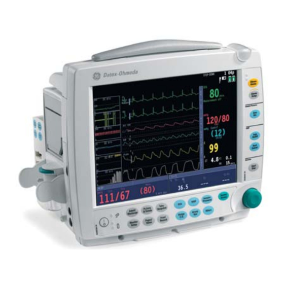
Monitor introduction (1) Battery compartment, see page 13 (2) Transportation handle (3) Alarm light, see page 33 (4) Alarm LEDs, see page 33 (5) Side panel keys, see page 12 (6) The ComWheel (7) Command Board keys, see page 10 (8) Guide rail for GCX mounting (9) Mains power and battery LEDs, see page 13 (10) ON/standby key... - Page 12 Rear panel connections (1) Slot for infusion pole mount (2) Module connector (marked with X4) (3) Guide rail for GCX mounting (4) Receptacle for power cord (5) Fuse holder (6) Serial port (marked with X9) (7) Network ID connector (marked with X8) (8) Connector for K-CREMCO (marked with X7) (9) Accessory: multi I/O adapter (with connectors 6 - 8 above)
- Page 13 Command Board keys Invasive Normal NIBP Pressures Screen Airway Wedge Others C.O. (1) ON/standby key (7) For returning the Normal Screen view to the screen (2) Mains power ON (lit) or OFF (dark): indicates mains or external (8) For activating pulse oximetry, impedance respiration and DC power temperature setup menus (3) For admitting or discharging a patient;...
- Page 14 Side panel keys Alarm LED indicators: see page 34 Silence For silencing the alarms, see page 36 Alarms Alarms For activating the Alarms Setup menu, see page 33 Setup Invasive Pressures For zeroing the invasive pressure channels, see page 69 Zero NOTE: Functional with the E-PSMP module only.
- Page 15 Batteries The S/5 FM has two lithium-ion batteries, located in the battery NOTE: Always use the S/5 FM with batteries inserted. Otherwise all compartment. They can be charged separately, and screen symbols trend data, snapshots and temporary settings are lost if the power and monitor frame LEDs indicate their charging level and possible cable is detached from the mains.
- Page 16 Replacing the batteries Battery capacity indicators in the upper right corner of the screen tell you when you should replace a battery, and which one is out of charge, missing or not working, see above. You can replace one battery at a time. To replace a battery: 1.
- Page 17 You can use simultaneously either one E-PSM(P) module or one N-Fx module or one of each. See the following pictures and There are five modules for the S/5 FM: hemodynamic Patient Side explanations for module features. Modules E-PSM and E-PSMP, and the S/5 FM specific Extension Modules N-FREC, N-FCREC and N-FC.
- Page 18 Module versions Module keys The Patient Side Modules have the following measurement Auto On/Off: for starting or capabilities: Start stopping the NIBP automatic Auto E-PSM: On/Off Cancel cycling, see page 67 Non-invasive blood pressure Start Cancel : for starting or Temperatures stopping the NIBP manual Pulse oximetry...
- Page 19 Extension Modules N-FREC, N-FCREC (in the drawing) and N-FC (1) Recorder, in N-FREC and N-FCREC (2) Paper compartment lever (3) CO measurement, in N-FCREC and N-FC (4) Water trap (5) Tab for removing the module (6) Sample gas inlet (7) Gas outlet Module versions The Extension Modules have the following measurement capabilities and features:...
- Page 20 Inserting a module Using two modules 1. Align the module with the insertion guides. E-PSM(P) and To install an E-PSM(P) and an N-Fx module: N-Fx modules are all inserted the same way. (1) Insert the N-Fx module first as explained in section 2.
-
Page 21: Monitoring Basics
Using modes pages for each mode. Pages are preconfigured but if desired, can also be changed. To select a page: The S/5 FM has six user modes. These user modes are predefined Pages/Views 1. Press the key or push the ComWheel once in the sets of parameters. - Page 22 For your notes:...
-
Page 23: Setting Up The Monitor Before Use
Setting up the monitor before use Before starting to use the monitor, check the monitor installation Battery setup settings and what is configured in different user modes, and make the necessary changes. The user modes can be hospital-specific. For Through this menu, you can check the battery status: more information about the default user modes, see the “Default Monitor Setup 1. - Page 24 Changing the monitor installation settings Printer The monitor installation settings are the same in all user modes. The ECG Printout Type: Select 2x6-25, 2x6-50 or 3x4-25. Monitor Setup Snapshot Printout: Select 12.5 or 25 mm. changes are preserved until changed again. Press Printer Connection: Select printer connection (default: None).
- Page 25 Changing the user modes Changing the start-up mode Monitor Setup 1. Select Install/Service - Save Modes. NOTE: If you want to make changes in user modes, we recommend 2. Select Startup Mode - 1, 2, 3, 4, 5 or 6. you contact the person responsible for the configuration.
- Page 26 Changing the waveform sweep speeds Changing the recorder settings Monitor Setup Print/Record 1. Select - Sweep Speeds. 1. Press 2. Select the parameters and adjust the values. Slow waveforms 2. Select Record Waveforms and select the recorded waveforms, show the amplitude changes better. delay, paper speed and length, and select if you wish to record waveforms on alarms.
- Page 27 Changing the Normal Screen layout Changing the layout of other pages Monitor Setup You can check the contents of the pages by pressing the 1. Press and select Screen 1 Setup: Pages/Views • Waveform Fields: Select the displayed waveforms. key. To change the layout of the pages: Monitor Setup.
- Page 28 Setting the default trend Setting trend length and time scale You can select graphical or numerical trends to be displayed by Pt.Data & Trends 1. Press default. • Select Trends – Graphical - Time Scale and the value. Monitor Setup 1.
-
Page 29: Starting And Ending
NOTE: Before using the monitor for the first time with batteries, charge 1. Prepare the patient connections according to the setup picture in the batteries to their full capacity (charging time 3 hours per battery the measurement section. Use only Datex-Ohmeda approved pack). supplies and accessories, see the “Supplies and Accessories”... - Page 30 Ending monitoring During monitoring Print/Record 1. Print necessary data: press the key. To remove a patient temporarily from the monitor, use standby: 2. Wait until the printing is finished. Then clear the patient data and 1. Disconnect patient cables or the measurement module and return the settings, including alarm limits, to their defaults through ensure that the monitor receives no vital signs and that the NIBP Admit/Discharge...
-
Page 31: Entering And Loading Patient Data
Select this when the monitor is connected to the network. This loads patient trends from the network. Note that the patient must have been The S/5 FM continuously saves patient data, such as trends. Saving is activated once the patient is admitted. The monitor saves discharged from the monitor less than 72 hours ago. - Page 32 For your notes:...
-
Page 33: Screen Setup
Screen setup Modifying the screen temporarily Changing the split screen contents You can split the Normal Screen page into two parts. The other half of • Press the Monitor Setup key and select Screen 1 Setup. the split screen shows trend or ST data. Change the waveform and digit field measurements, split screen Monitor Setup 1. - Page 34 − Selecting Combine Pressures displays invasive pressures in the Changing waveform and digit fields same waveform field with the same zero line, but with individual scales. Up to six waveforms and four digit fields can be displayed simultaneously. − If 5- or 12-lead ECG is measured, up to three different ECG leads •...
-
Page 35: Alarms
Alarms Enabling the alarms Alarm indications To enable the alarms, connect patient cables. If the alarm source is When the monitor is turned on, you will hear a beep: this tells you that selected, the alarms are operative also when the measurement is not the alarm audio signal is working. - Page 36 Alarm categories The priority depends primarily on the cause and alarm duration. Visual Meaning Tone pattern (selected when the Side panel LED indicators Alarm light system is configured) (if enabled) For life threatening situations Triple + double beep every 5 seconds or red LED lit flashing red continuous beep...
- Page 37 User’s Reference Manual: Alarms" for details. Alarm light Showing alarm history The S/5 FM has an alarm light, located in the upper right corner of the monitor frame, see page 9. The alarm light can be enabled • Press the Pt.Data &...
- Page 38 Silencing audible alarms permanently Silencing audible alarms temporarily Alarms Setup 1. Press the side panel key and select Audio Silence Alarms To silence alarms for two minutes, press the side ON/OFF. panel key. To silence them for five minutes, press the key for more than 2.
-
Page 39: Trends And Snapshots
Trends and snapshots Graphical trend view Viewing graphical trends • Press the Pt.Data & Trends key and select Trends -Graphical. • To see more parameters, select Scroll Pages and scroll with the ComWheel. • To see more data, select Cursor and scroll with the ComWheel. Graphical trends contain four trend pages each having up to six preconfigured fields with different parameters. - Page 40 Viewing numerical trends Automatic snapshots Pt.Data & Trends Automatic snapshot creation can be defined separately for each 1. Press the key. arrhythmia alarm. For more details, see section "ECG/ST" and 2. Select Trends - Numerical. section "Setting up the monitor before use." •...
-
Page 41: Printing And Recording
Printing and recording You need Side panel key − Laser printer for printouts (PCL5 compatible, min. 2Mb memory, Starts and stops recording serial or parallel printer; for parallel port printer accessories, see below) − Optional N-FREC or N-FCREC module for recording −... - Page 42 Printing currently displayed screen contents Printing with a laser printer You can print currently displayed trend data, calculation trends, ECG waveforms and calculations. Selecting a printer Print/Record 1. Press the key. To print trend data: 2. Select Printer Connection. • Press the Pt.Data &...
- Page 43 Recording graphical trends Recording with the recorder Print/Record 1. Press the key. NOTE: You need the N-FREC or N-FCREC module with the built-in 2. Select Record Trends - Record Graphical. recorder. 3. You can stop recording by selecting Stop Graphical. Recording numerical trends Trends are recorded for the time period that corresponds to the time You can record the current values of measured parameters.
- Page 44 Recording on alarms Recording waveforms Print/Record You can record three waveforms to a local recorder, and two to four 1. Press the key. waveforms to a network recorder: 2. Select Record Waveforms. 3. Select Start on Alarms - YES. Print/Record 1.
-
Page 45: Laboratory Data And Calculations
Laboratory data and calculations For more information, please refer to the “User’s Reference Manual.” Temperature correction In the laboratory, blood gas values are measured and calibrated at Entering laboratory values +37°C. These values may need to be adjusted to the actual patient Pt.Data &... - Page 46 Hemodynamic or oxygenation calculations Viewing calculations Wedge C.O. To view values of the three most recent calculations: 1. Press the key. Wedge C.O. 2. Select Calculations - Hemodynamic Calcs or Oxygenation Calcs. 1. Press the key. 3. Enter or edit the measurement data using the ComWheel. 2.
- Page 47 Drug calculator Performing drug calculations The S/5 FM also includes a drug calculator and a titration table, Pt.Data & Trends 1. Press the key. which can be used for determining the correct infusion or drip rates. 2. Select Drug Calculator.
- Page 48 Titration table Printing or recording the titration table The titration table gives 50 titration values for the selected drug. The In some cases, the titration table may be required near the patient. monitor displays both infusion rates and drip rates. If required, both You can print the table on the recorder in modules N-FREC and the starting dose and the increment steps can be edited through the N-FCREC, or on a laser printer.
-
Page 49: Interfacing External Devices
With the Datex-Ohmeda S/5 Device Interfacing Solution, DIS, you can interface simultaneously up to four devices, like monitors and blood gas analyzers, to the Datex-Ohmeda monitoring system. The real-time and trended parameter data can be displayed on the monitor screen and used for calculations. - Page 50 Connecting external devices Checking the functioning of the S/5 DIS You can check the functioning of the S/5 DIS in two ways: Label specifying the external device Monitor Setup key and select Interfacing - Status 1. Press the LED indicators Page.
-
Page 51: Cleaning And Care
Permitted detergents Permitted disinfectants DO NOT! − − • Do not use hypochlorite, acetone-, phenol- or Datex-Ohmeda Cleaning Fluid Ethanol ammonia based cleaners. − − Other mild detergents Isopropyl alcohol • Do not autoclave the device or its parts. - Page 52 Power interruption supply. NOTE: Always use the S/5 FM with batteries inserted. Otherwise all trend data, snapshots and temporary settings are lost if the power cable is detached from the mains.
- Page 53 Regular checks NIBP • • Check that the ECG waveforms are displayed when the cable is Ensure that you are using correct cuff size and have selected connected to the patient. When the cable is disconnected from correct inflation limits. the patient, the message 'Leads off' is displayed.
- Page 54 Calibrating 1. Turn on the power. Let the monitor warm up for 30 minutes. Calibration check of temperature, NIBP and invasive blood 2. Attach a regulator to the calibration gas container. pressures 3. Attach a new sampling line to the water trap. Connect the other Calibration check of temperature, NIBP and invasive blood pressures end of the sampling line to the regulator on the gas container.
-
Page 55: Ecg/St
ECG/ST NOTE: For a comprehensive list of accessories, see the “Supplies and You need Accessories” catalog delivered with the monitor. (1) E-PSM or E-PSMP module (2) Multi-Link 5-lead or 12-lead standard cable NOTE: In 5-lead ECG, place the 5th electrode (C/V) in one of the six (3) Multi-Link leadwire set (3 or 5 leads) places indicated, and select the corresponding V lead label. - Page 56 Connecting ECG leadwire sets to ECG trunk cables 12-lead placement according to Mason-Likar • • For 3-lead ECG, connect the Multi-Link 3 leadwire set to the The arm leads are located just below the clavicles in the 5- or 12-lead standard cable. You can also use the Multi-Link 3- infraclavicular fossae.
- Page 57 Preparing the patient and applying the electrodes Selecting the number of electrodes 1. Prepare the skin properly to ensure optimal signal quality: 1. Press the key. • Shave any hair from the electrode sites. 2. Select ECG Setup. • Gently rub the skin surface to increase capillary blood flow 3.
- Page 58 Selecting how to view ECG waveforms Changing the HR source • To set the number of ECG waveforms in Normal Screen, press • Press the key and select ECG Setup - HR Source. Monitor Setup AUTO selects the first available of ECG, Art, ABP and Pleth. and select Screen 1 Setup - Waveform Fields.
- Page 59 WARNING: The impedance respiration measurement Monitoring pacemaker patients may cause rate changes in Minute Ventilation Rate Responsive Pacemakers. Set the pacemaker rate 1. Press the key. responsive mode off or turn off the impedance 2. Select ECG Setup - Pacemaker and select one of the following: respiration measurement on the monitor.
- Page 60 For your notes:...
- Page 61 Arrhythmia monitoring NOTE: For optimal results, select STfilt as the ECG filter. For details, see page 55. Selecting arrhythmia analysis mode Starting relearning manually NOTE: With the L-FICU03 software license only severe analysis is When the patient’s ECG pattern changes considerably, the monitor available.
- Page 62 Detecting arrhythmia alarms NOTE: A clinician must analyze the arrhythmia information in conjunction with other clinical findings. For details about detection performance and test results of the arrhythmia algorithm testing, please refer to “User’s Reference Manual: ECG.” Alarm Criteria Asystole Cardiac arrest, no QRS complexes for five seconds Bradycardia HR below the HR alarm limit...
- Page 63 Monitoring ST The monitor analyzes ST for all measured leads and gives ST trends separately for each lead. The ST analysis starts automatically after the leads have been connected, the QRS detection has started and the ECG filter selection is either STfilt or Diagn. ST can be viewed as digits, average and reference complexes and trends.
- Page 64 Studying ST Trends Viewing ST in split screen • Press Pages/Views and select ST View - ST Trends. • Press Monitor Setup and select Screen 1 Setup- Split Screen - QRS complexes and trends for the three user leads are displayed ST.
-
Page 65: Impedance Respiration
Impedance respiration You need Correcting the respiration number − The same setup as in the ECG measurement, see section "ECG/ST." Normally, the AUTO detection limit is recommended. However, if the respirations are particularly weak or affected by artifacts, they may Starting not be included in the respiration rate. -
Page 66: Temperature
(3) Reusable temperature probe (4) Adapter cable for disposable temperature probes (5) Disposable temperature probe NOTE: Use only Datex-Ohmeda temperature probes or defibrillator-proof YSI 400 series probes. NOTE: For a comprehensive list of accessories, see the “Supplies and Accessories” catalog delivered with the monitor. -
Page 67: Pulse Oximetry
Pulse oximetry NOTE: For each SpO accessory, refer to the instructions for use in the You need accessory package for patient weight limits. (1) E-PSM or E-PSMP module WARNING: Allow sensor and cable to dry completely (2) OxyTip+ interconnect cable after cleaning. - Page 68 − The pulse oximeter cannot distinguish between oxyhemoglobin and dyshemoglobins, for example, met- or carboxyhemoglobins. NOTE: Datex-Ohmeda sensors are latex-free. − Poor perfusion may affect the accuracy of measurement when using the ear probe. WARNING: Change measuring site frequently. Change −...
-
Page 69: Nibp
NIBP You need NOTE: For a comprehensive list of accessories, see the “Supplies and Accessories” catalog delivered with the monitor. (1) E-PSM or E-PSMP module (2) Cuff hose WARNING: Vibrations during intrahospital transport (3) Cuff of correct size may disturb NIBP measurement. WARNING: Non-invasive blood pressure measurement is intended for patients weighing over 5 kg (11 lb). - Page 70 NOTE: The presence of some arrhythmias during NIBP measurement Starting may increase the time required for the measurement. For details about the test results of the functioning of the NIBP measurement in The monitor sets inflation limits automatically for adults and infants the presence of arrhythmias, see the "User’s Reference Manual: according to the hose used.
-
Page 71: Invasive Blood Pressure
Invasive blood pressure You need You can monitor up to two pressure channels with the E-PSMP module by using a dual cable. (1) E-PSMP module with InvBP measurement capability NOTE: For a comprehensive list of sensors and accessories, see the (2) Heparinized fluid bag with pressure infusor “Supplies and Accessories”... - Page 72 Starting Labeling channels • For the setup, prepare the transducer kit according to the The label of the pressure channel sets its display scale, color, filter, alarm source and alarm limits. The label descriptions are manufacturer’s instructions. preconfigured. • Ensure that there is no air in the line. •...
- Page 73 Combining pressures Determining pressure values visually All invasive pressure waveforms can be displayed together so that By moving the horizontal cursor across the pressure waveform, you they use an area of two normal waveforms, or so that all are can get accurate pressure values at selected points. This may be combined in the same field with the same zero line.
- Page 74 Adjusting PCWP Pulmonary Capillary Wedge Pressure (PCWP) To manually adjust the wedge pressure level: 1. In the Wedge menu, turn the ComWheel to move the cursor to a Starting point that represents the true PCWP level. 1. Prepare the pulmonary artery catheter and use the distal lumen 2.
-
Page 75: Airway Gas
Airway gas You need You get − N-FCREC or N-FC module with CO Carbon dioxide measurement: EtCO , FiCO , capnogram. measurement capability Respiratory rate − Gas sampling line − Airway adapter with sampling line connector − Water trap NOTE: For a comprehensive list of accessories, see the “Supplies and Accessories”... - Page 76 Starting Waveform scaling • Connect the gas sampling line to the airway adapter and to the If EtCO is above 6% or the difference between FiO and EtO is above 6%, change the scale for capnogram: module. Airway Gas • Before connecting the patient, check that the message 1.
-
Page 77: Troubleshooting
Troubleshooting NOTE: Always check the patient’s condition first in problematic situations or if an alarm is triggered. See also section “Messages." Also note that if the measurement or function does not appear on the screen, check module connections. PROBLEM RELATED TO: CAUSE WHAT TO DO Airway gases... - Page 78 PROBLEM RELATED TO: CAUSE WHAT TO DO • Make sure there are no air bubbles in the transducer system. Invasive Flush and zero. InvBP readings seem unstable pressures • Place the transducer on the patient’s mid-heart level and zero. • For battery operation, check that the batteries are inserted and charged, see page 13.
-
Page 79: Messages
Messages MESSAGE CAUSE WHAT TO DO Air leakage NIBP: There is an air leak in the cuff or hose. Check all connections and test tightness using venous stasis. Alarms Alarms acknowledged from Silenced alarms remain silent. New alarms will have an If required, turn on the alarms through Setup Central... - Page 80 MESSAGE CAUSE WHAT TO DO Check NIBP NIBP measurement affected by low blood pressure and Check patient status, measurement setup and pulsation, or a change in patient’s condition. cuff. Check probe : There is no detectable SpO signal, the sensor is Check the sensor and connections.
- Page 81 MESSAGE CAUSE WHAT TO DO NIBP manual NIBP: Air leak or loose cuff have interrupted the Check setup and restart autocycling. autocycling mode No battery backup There are no batteries or they have both failed. Replace the batteries; see section “Replacing the batteries.”...
- Page 82 MESSAGE CAUSE WHAT TO DO SpO2 probe off : The finger or ear lobe may be too thin or sensor Check connection between sensor and patient. halves are not aligned. Sensor may be defective. Replace the sensor. SRAM error Memory checking failed. Contact authorized service personnel.
-
Page 83: Abbreviations
Abbreviations /min beats per minute, breaths per ATPD atmospheric/ambient calculated/derived value minute temperature and pressure, dry chest °C Celsius degree C(a-v)O arteriovenous oxygen content °F Fahrenheit degree ATPS ambient temperature and difference µg microgram pressure, saturated gas C.I. cardiac index alveolar airway C.O. - Page 84 Core core temperature emergency department FEMG frontal electromyogram Count count of responses end-diastolic volume fast Fourier transform FI, Fi fraction of inspired gas cardiopulmonary bypass EDVI end-diastolic volume index cerebral perfusion pressure energy expenditure (kcal/24h) FiAA fraction of inspired anesthetic compressed spectral array electroencephalogram agent...
- Page 85 heat and moisture exchanger International Standards minimum alveolar Organisation concentration HMEF heat and moisture exchanger with filter isoflurane maximum hectopascal idioventricular rhythm mbar millibar HR dif heart rate difference joule microgram heart rate mean mean blood pressure height kelvin milliequivalent hardware kcal kilocalorie...
- Page 86 neutral P(g-ET)CO difference between PEEPe+PEEPi nitrogen gastrointestinal carbon dioxide total positive end expiratory and end tidal carbon dioxide pressure (ICU) nitrous oxide sodium concentration PEEPi intrinsic positive end expiratory P(STPD) pressure in STPD conditions pressure Naso nasopharyngeal temperature P1..6 invasive pressure channel PEEPtot total positive end expiratory neonate...
- Page 87 polyvinylchloride RVEDV right ventricular end-diastolic STfilt ST filter (ECG) volume premature ventricular contraction STPD standard temperature and PVloop pressure volume loop RVESV right ventricular end-systolic pressure, dry gas partial pressure of oxygen in volume Surf surface temperature right ventricular pressure (mixed) venous blood software RVSW...
- Page 88 TOF% ratio of the 4th to the 1st venous WLAN wireless local area network response (NMT) ventricular oxygen consumption Trigem. trigeminy volume calc calculated oxygen tidal volume ventilation/perfusion ratio consumption* TVexp expired tidal volume (ml) V0.5 volume expired during the first oxygen consumption index TVinsp inspired tidal volume (ml)
-
Page 89: Performance
E-PSMP NIBP (IEC 60601-2-30) and invasive pressure cause inaccurate results. (IEC 60601-2-34) standard requirements. Datex-Ohmeda S/5 FM Silencing alarms for 5 minutes does not comply with Filter modes: the SpO (ISO 9919) standard requirements. monitoring filter 0.5 to 30 Hz... - Page 90 equipment typically cause false positive pacer Direct cardiac application: ECG (cont.) detection. The display area reserved for the ECG measurement Direct current for leads-off detection through an in the S/5 monitoring system screen may not be Heart rate: active patient electrode: <30 nA adequate for displaying the complete ECG Measurement range: 30 to 250 bpm Direct current for leads-off detection through a...
- Page 91 ±0.3°C (10 to 24.9°C) between the cuff and the NIBP measuring patient weight limits. Probe type: Use only Datex-Ohmeda temperature electronics. probes or defibrillator-proof YSI 400 series probes. Temperature NOTE: NIBP measurement is intended for patients...
- Page 92 Halothane (4%) increases < 0.3 vol% Respiration rate Airway gases, N-FCREC and N-FC Isoflurane(5%) increases < 0.4 vol% Breath detection: 1% change in CO level Sampling rate: 150±25 ml/min (sampling line Enflurane(5%) increases < 0.4 vol% Measurement range: 4 to 80 breaths/min 2 to 3 m, normal conditions) Desflurane(24%) increases <...
-
Page 93: End User License Agreement
THIS DOCUMENT IS A LEGAL AGREEMENT BETWEEN YOU, THE 4. Copy Restrictions. The software/firmware and the accompanying "PURCHASER," AND DATEX-OHMEDA (“D-O”). IF YOU DO NOT written materials are copyrighted. Unauthorized copying of the AGREE TO THE TERMS OF THIS AGREEMENT, PROMPTLY RETURN THE... -
Page 94: Warranty
Warranty This Product is sold by Datex-Ohmeda under the warranty set forth in Datex-Ohmeda’s sole and exclusive obligation and Buyer’s sole and the following paragraphs. Such warranty is extended only with respect exclusive remedy under the above warranty is limited to repairing or to the purchase of this Product directly from Datex-Ohmeda or Datex- replacing, free of charge, at Datex-Ohmeda’s option, a Product, which...
Need help?
Do you have a question about the S/5 FM and is the answer not in the manual?
Questions and answers