Table of Contents
Advertisement
Quick Links
Advertisement
Table of Contents

Related Manuals for Advantech AMAX-5000 Series


Summary of Contents for Advantech AMAX-5000 Series
- Page 1 User Manual AMAX-5000 Series EtherCAT Slice I/O Modules...
- Page 2 No part of this manual may be reproduced, copied, translated or transmitted in any form or by any means without the prior written permission of Advantech Co., Ltd. Information provided in this manual is intended to be accurate and reliable. How- ever, Advantech Co., Ltd.
- Page 3 This product has passed the CE test for environmental specifications when shielded cables are used for external wiring. We recommend the use of shielded cables. This kind of cable is available from Advantech. Please contact your local supplier for ordering information.
- Page 4 In accordance with IEC 704-1:1982 specifications, the sound pressure level at the operator's position does not exceed 70 dB (A). DISCLAIMER: These instructions are provided according to IEC 704-1 standards. Advantech disclaims all responsibility for the accuracy of any statements contained herein. AMAX-5000 Series User Manual...
-
Page 5: Table Of Contents
Contents Chapter Introduction..........1 Introduction to AMAX-5000 Slice I/O Module..........2 Table 1.1: AMAX-5000 series extension modules....... 2 Object for Internal Settings................ 4 1.2.1 Standard Object (0x1000 - 0x1FFF) ..........4 Chapter Hardware Installation ......7 Install / Remove the Module..............8 2.1.1... - Page 6 Table 4.17:Configuration Data (0x8000 - 0x8FFF)..... 42 Table 4.18:Alarm Status for 4 ~ 20 mA Input Range ....42 Table 4.19:Input Range Type............. 42 Table 4.20:Burnout value ............42 Table 4.21:Configuration Data (0xF600 - 0xFFFF) ....43 AMAX-5000 Series User Manual...
- Page 7 Table 4.43:Upper 4 Pin Connector ..........60 Table 4.44:Lower 8 Pin Connector ..........60 4.5.4 Application Wiring ............... 60 Figure 4.25Wiring for AMAX-5018..........60 4.5.5 AMAX-5018 Object Dictionary ............ 61 Table 4.45:Analog Input (0x6000 - 0x6FFF)....... 61 AMAX-5000 Series User Manual...
- Page 8 Figure 5.6 AMAX-5052 Module ..........77 5.2.1 AMAX-5052 Specification ............77 5.2.2 LED Indicator ................78 Figure 5.7 AMAX-5052 Module LED Indicator ......78 Table 5.6: AMAX-5052Module LED Indicator ......78 5.2.3 Pin Definition................79 AMAX-5000 Series User Manual viii...
- Page 9 AMAX-5057 Object Dictionary ............ 96 Table 5.24:Output Data (0x3101 – 0x3102) ....... 96 Table 5.25:SM0, PDO assignment 0x1C10 (not changeable)..96 AMAX-5057SO 16-ch Source-type Digital Output Module...... 97 Figure 5.26AMAX-5057SO Module ..........97 5.6.1 AMAX-5057SO Specification ............97 AMAX-5000 Series User Manual...
- Page 10 Table 6.16:SM3, PDO assignment 0x1C13 (not changeable) . 120 AMAX-5081 1-ch TTL/RS-422 Encoder/Counter Module ..... 121 Figure 6.13AMAX-5081 Module ..........121 6.2.1 AMAX-5081 Specification ............122 6.2.2 LED Indicator ................123 Figure 6.14AMAX-5081 Module LED Indicator ......123 Table 6.17:LED Indicator............123 AMAX-5000 Series User Manual...
- Page 11 Table 6.32:Configuration Data (0xF600 - 0xFFFF) ....148 Table 6.33:SM2, PDO assignment 0x1C12 (selectable) ..149 Table 6.34:SM3, PDO assignment 0x1C13 (selectable) ..149 Chapter Digital I/O Module with Timestamp The Benefit of Time-stamping Digital I/O ..........152 AMAX-5000 Series User Manual...
- Page 12 Table 7.13:Output Data (0x1D09) ..........168 Table 7.14:Output Data (0x3000)..........168 Table 7.15:SM0, PDO assignment 0x1C10 (selectable)..168 Table 7.16:SM1, PDO assignment 0x1C11 (selectable)..168 Table 7.17:SM2, PDO assignment 0x1C12 (not changeable) . 168 Table 7.18:SM3, PDO assignment 0x1C13 (selectable)..168 AMAX-5000 Series User Manual...
-
Page 13: Chapter 1 Introduction
Chapter Introduction... -
Page 14: Introduction To Amax-5000 Slice I/O Module
Introduction to AMAX-5000 Slice I/O Module This manual will only introduce AMAX-5000 series slice I/O modules. To know more about the AMAX-5580 controller and AMAX-5400 series extension modules, please download AMAX-5580 user manual from our website. Advantech provides different I/O modules for various applications. The following table outlines Advantech's supported I/O modules. - Page 15 - DI Voltage: 11~30V AMAX-5051T - timestamp resolution: 1ns - Input delay: < 0.5us Digital I/O Module withTimestamp 2-ch Timestamp digital output module - DO voltage: 10~30V AMAX-5056T - timestamp resolution: 1ns - Output delay: < 0.5us AMAX-5000 Series User Manual...
-
Page 16: Object For Internal Settings
The definition of product code (0xaaaabbbb) as below: aaaa: Product series 0003: AMAX-5000 bbbb: Product ID 5001: AMAX-5001 5015: AMAX-5015 … Revision (4bytes): The definition of revision (0xaabbcdee) as below: aa: Reserved bb: Product sub ID AMAX-5000 Series User Manual... - Page 17 0x0000 0004 EtherCAT Coupler w/ ID Switch Module AMAX-5079 NA (Not an EtherCAT slave) EtherCAT Extension Module 2-ch 24V HTL Encoder/Counter Mod- AMAX-5080 0x0003 5080 0x0000 0005 1-ch TTL/RS-422 Encoder/Counter AMAX-5081 0x0003 5081 0x0000 0001 Module AMAX-5000 Series User Manual...
- Page 18 AMAX-5000 Series User Manual...
-
Page 19: Chapter 2 Hardware Installation
Chapter Hardware Installation... -
Page 20: Install / Remove The Module
Install / Remove the Module AMAX-5000 series is an easy-install design to help you maintain your modules eas- ily. 2.1.1 Attach on the DIN-rail Follow these steps to secure AMAX-5000 modules on the DIN-rail: Unlock the latches at the bottom of AMAX-5000 module. -
Page 21: Remove From The Din-Rail
You can easily detach the module by releasing the latch at the bottom of the module. Then you can pull out the module without any difficulty. Figure 2.2 Unlock the latch to remove the module Figure 2.3 AMAX-5000 module design AMAX-5000 Series User Manual... -
Page 22: I/O Wiring
AMAX-5000 I/O module. Use the screw driver to press the left notch on the terminal. Insert the wire into the terminal. Note! Please use # 14 AWG ~ 28 AWG wire for terminal block. Dimensions AMAX-5000 Series User Manual... - Page 23 AMAX-5000 Series User Manual...
- Page 24 AMAX-5000 Series User Manual...
-
Page 25: Chapter 3 Infrastructure
Chapter Infrastructure... -
Page 26: Amax-5001 Smart Power Input Module With 4-Ch Di
Status on the process data is shown on the LED. AMAX-5001 is also equipped with 4-ch wet contact DI for users to connect to system events. Figure 3.1 AMAX-5001 Module AMAX-5000 Series User Manual... -
Page 27: Amax-5001 Application
Weight: Approx. 80g 3.1.2.2 Power Input Rated Voltage: 24V (±20%) Dual Power Input: Supported Max Current on Bus: 2A Diagnosis Function: – Over/under voltage for input 1&2 – Over current output on bus AMAX-5000 Series User Manual... -
Page 28: Led Indicator
Table 3.1: AMAX-5001 Module LED Indicator Color Indication Behavior Green Power on Green EtherCAT connection Green BUS power on BUS over current Vin1 over voltage (30V) Vin2 over voltage (30V) Vin1 under voltage (10.7V) Vin2 under voltage (10.7V) AMAX-5000 Series User Manual... -
Page 29: Pin Definition
3.1.4 Pin Definition Figure 3.4 AMAX-5001 Module Front View Figure 3.5 AMAX-5001 Module Side View AMAX-5000 Series User Manual... -
Page 30: Application Wiring
Table 3.2: Upper 4 Pin Connector Pin Number Pin Definition Table 3.3: Lower 8 Pin Connector Pin Number Pin Definition DI_COM DI_COM 3.1.5 Application Wiring Figure 3.6 Wiring for AMAX-5001 Digital Input Figure 3.7 Wiring for AMAX-5001 Power Input AMAX-5000 Series User Manual... -
Page 31: Amax-5001 Object Dictionary
Index Size (byte.bit) Name PDO content 0x1A00 32.0 Inputs process data 6000:01 Over_Voltage_1; mapping 6000:02 Under_Voltage_1; 6000:03 Over_Voltage_2; 6000:04 Under_Voltage_2; 6000:05 Over_Current; 6000:06 DI0; 6000:07 DI1; 6000:08 DI2; 6000:09 DI3; 6000:11 Voltage_1; 6000:12 Voltage_2; 6000:13 Current AMAX-5000 Series User Manual... -
Page 32: Amax-5074 Ethercat Coupler With Id Switch
Connector’: Pluggable 4P push-in terminal (#24~16 AWG) and 2x RJ45 Enclosure: PC Power Consumption: 2.5W @ 24V Protocol: EtherCAT Transmission Rate: 100Mbps Distributed Clock: Default not supported LED Indicator: PWR, RUN, Power Diagnosis LED Weight: Approx. 97g AMAX-5000 Series User Manual... -
Page 33: Led Indicator
Bus Interface: 2 x RJ45 (1 x Input, 1 x Output) 3.2.1.4 Environment Operation Temperature: -25~60°C (vertical mounted) Storage Temperature: -40~85°C Relative Humidity: 5~95% (non-condensing) 3.2.2 LED Indicator Figure 3.9 AMAX-5074 Module LED Indicator AMAX-5000 Series User Manual... -
Page 34: Id Switch
Table 3.8: AMAX-5074 ID Switch Switch Number Multiple Range (HEX) Example (SW2, SW1) = (4, C), then ID = 4 x16 + C x1 = 76 Note! Function Reserved, hot connection is currently not supported in CODE- SYS. AMAX-5000 Series User Manual... -
Page 35: Pin Definition
3.2.4 Pin Definition Figure 3.11 AMAX-5074 Module Front View Figure 3.12 AMAX-5074 Module Side View AMAX-5000 Series User Manual... -
Page 36: Application Wiring
Bus current > 2A UINT 0x00 6000:06 Device_ID ID Switch UINT 0x00 6000:11 Voltage_1 Input voltage 1 REAL 0x0000 (0 Dec) 6000:12 Voltage_2 Input voltage 2 REAL 0x0000 (0 Dec) 6000:13 Current Input current REAL 0x0000 (0 Dec) AMAX-5000 Series User Manual... - Page 37 Table 3.13: SM3, PDO assignment 0x1C13 (not changeable) Index Size (byte.bit) Name PDO content 0x1A00 24.0 Inputs process data 6000:01 Over_Voltage_1; mapping 6000:02 Under_Voltage_1; 6000:03 Over_Voltage_2; 6000:04 Under_Voltage_2; 6000:05 Over_Current; 6000:06 Device_ID; 6000:11 Voltage_1; 6000:12 Voltage_2; 6000:13 Current AMAX-5000 Series User Manual...
-
Page 38: Amax-5079 Ethercat Extension
AMAX-5079 Specification 3.3.1.1 General: Certification: CE, FCC class A Connector’: 1 x RJ45 Enclosure: PC Power Consumption: N/A Protocol: EtherCAT Transmission Rate: 100Mbps LED Indicator: N/A Weight: Approx. 71g AMAX-5000 Series User Manual... -
Page 39: Pin Definition
Bus Interface: 1 x RJ45 Power from bus: N/A 3.3.1.3 Environment Operation Temperature: -25~60°C (vertical mounted) Storage Temperature: -40~85°C Relative Humidity: 5~95% (non-condensing) 3.3.2 Pin Definition Figure 3.15 AMAX-5079 Module Front View AMAX-5000 Series User Manual... - Page 40 Figure 3.16 AMAX-5079 Module Side View Table 3.14: LAN Port LAN Number LAN Definition EtherCAT signal output AMAX-5000 Series User Manual...
-
Page 41: Chapter 4 Analog Input/Output Modules
Chapter Analog Input/Output Modules... -
Page 42: Amax-5015 4-Ch Rtd Input Module
Connector: Pluggable 4P+8P push-in terminal (#24~16 AWG) Enclosure: PC Power Consumption: 2W @ 24VDC Protocol: EtherCAT Transmission Rate: 100Mbps Distributed Clock: Default not supported LED Indicator: PWR, RUN Weight: Approx. 80g AMAX-5000 Series User Manual... - Page 43 Resolution: 16 bit with ±0.1% FSR accuracy @25°C Sample Rate: 100 sample/s (per channel) Burn-out detection: Yes 4.1.1.3 Protection Isolation Voltage: 2000V 4.1.1.4 Environment Operation Temperature: -25~60°C (vertical mounted) Storage Temperature: -40~85°C Relative Humidity: 5~95% (non-condensing) AMAX-5000 Series User Manual...
-
Page 44: Led Indicator
Figure 4.2 AMAX-5015 Module LED Indicator Table 4.1: AMAX-5015 Module LED Indicator Color Indication Behavior Green Power on Power Yellow Locating Module EtherCAT Connected Green Blink EtherCAT Connecting Run/Error EtherCAT Abnormal ON/Blink System Abnormal No Error AMAX-5000 Series User Manual... -
Page 45: Pin Definition
4.1.3 Pin Definition Figure 4.3 AMAX-5015 Module Front View Figure 4.4 AMAX-5015 Module Side View AMAX-5000 Series User Manual... -
Page 46: Application Wiring
Table 4.2: Upper 4 Pin Connector Pin Number Pin Definition RTD0+ RTD0- COM0 RTD1+ Table 4.3: Lower 8 Pin Connector Pin Number Pin Definition RTD1- COM1 RTD2+ RTD2- COM2 RTD3+ RTD3- COM3 4.1.4 Application Wiring Figure 4.5 Wiring for AMAX-5015 AMAX-5000 Series User Manual... -
Page 47: Amax-5015 Object Dictionary
Data type Flags Default value (hex) 80n0:01 AIn_EnBurnOut Enable burnout BOOL 0x01 (Enable) detection 80n0:11 AIn_Range Input range type UINT 0x3A4 (Pt100 (385) -50~150 °C) 80n0:14 AIn_BurnOutValue Burnout value UINT 1 (Up Scale) (n=0~3 for ch0~3) AMAX-5000 Series User Manual... - Page 48 Table 4.12: SM3, PDO assignment 0x1C13 (not changeable) Index Size (byte.bit) Name PDO content 0x1A0n 10.0 Analog Input Channel n 60n0:01 AIn_BurnOut; process data mapping 60n0:02 AIn_OverRange; 60n0:03 AIn_UnderRange; 60n0:11 AIn_Raw; 60n0:13 AIn_Scale (n=0~3 for ch0~3) AMAX-5000 Series User Manual...
-
Page 49: Amax-5017C 6-Ch Current Input Module
The module provides 2000V isolation between channels. If any high voltage or current damage the channels, the whole system (other modules and control unit) won't be affected because it is already isolated. Figure 4.6 AMAX-5017C Module AMAX-5000 Series User Manual... -
Page 50: Amax-5017C Specification
Environment Operation Temperature: -25~60°C (vertical mounted) Storage Temperature: -40~85°C Operating Humidity: 20 ~ 95% RH (non-condensing) Storage Humidity: 0 ~ 95% RH (non-condensing) 4.2.2 LED Indicator Figure 4.7 AMAX-5017C Module LED Indicator AMAX-5000 Series User Manual... -
Page 51: Pin Definition
Table 4.13: AMAX-5017C Module LED Indicator Color Indication Behavior Green Power on Power Yellow Locating Module EtherCAT Connected Green Blink EtherCAT Connecting Run/Error EtherCAT Abnormal ON/Blink System Abnormal No Error 4.2.3 Pin Definition Figure 4.8 AMAX-5017C Module Front View AMAX-5000 Series User Manual... - Page 52 Figure 4.9 AMAX-5017C Module Side View Table 4.14: Upper 4 Pin Connector Pin Number Pin Definition Table 4.15: Lower 8 Pin Connector Pin Number Pin Definition AMAX-5000 Series User Manual...
-
Page 53: Application Wiring
(n=0~5 for ch0~5) Converting current input value: For the range 4~20 mA: × 16 ) + 4 65536 For the range ± 20 mA: × 40 65536 For the range 0~20 mA: × 20 65536 AMAX-5000 Series User Manual... - Page 54 Table 4.19: Input Range Type Range Type Value (UINT) 4~20 mA 0x180 ± 20 mA (Full Scale Range) 0x181 0~20 mA 0x182 Table 4.20: Burnout value Item Name Value (UINT) Down Scale (output 0) Up Scale (output 65535) AMAX-5000 Series User Manual...
- Page 55 PDO assignment (0x1C10 – 0x1C13) Table 4.23: SM3, PDO assignment 0x1C13 (not changeable) Index Size (byte.bit) Name PDO content 0x1A0n Analog Input Channel n pro- 60n0:01 AIn_BurnOut; cess data mapping 60n0:02 AIn_OverRange; 60n0:03 AIn_UnderRange; 60n0:11 AIn (n=0~5 for ch0~5) AMAX-5000 Series User Manual...
-
Page 56: Amax-5017V 6-Ch Voltage Input Module
(other modules and control unit) won't be affected cause it is already isolated. Figure 4.11 AMAX-5017V Module 4.3.1 AMAX-5017V Specification 4.3.1.1 General Certification: CE, FCC class A Protocol: EtherCAT Baud Rate: 100M bps Weight: Approx. 80g AMAX-5000 Series User Manual... -
Page 57: Led Indicator
Figure 4.12 AMAX-5017V Module LED Indicator Table 4.24: AMAX-5017V Module LED Indicator Color Indication Behavior Green Power on Power Yellow Locating Module EtherCAT Connected Green Blink EtherCAT Connecting Run/Error EtherCAT Abnormal ON/Blink System Abnormal No Error AMAX-5000 Series User Manual... -
Page 58: Pin Definition
4.3.3 Pin Definition Figure 4.13 AMAX-5017V Module Front View Figure 4.14 AMAX-5017V Module Side View AMAX-5000 Series User Manual... -
Page 59: Application Wiring
Table 4.25: Upper 4 Pin Connector Pin Number Pin Definition Table 4.26: Lower 8 Pin Connector Pin Number Pin Definition 4.3.4 Application Wiring Figure 4.15 Wiring for AMAX-5017V AMAX-5000 Series User Manual... -
Page 60: Amax-5017V Object Dictionary
× 20 ) 65536 For the range 0~150 mV: × 150 65536 For the range 0~500 mV: × 500 65536 For the range 0~1 V: × 1 65536 For the range 0~5 V: × 5 65536 AMAX-5000 Series User Manual... - Page 61 600Hz 0x01 4.3.5.4 PDO assignment (0x1C10 – 0x1C13) Table 4.32: SM3, PDO assignment 0x1C13 (not changeable) Index Size (byte.bit) Name PDO content 0x1A0n Analog Input Channel n process data mapping 60n0:11 AIn (n=0~5 for ch0~5) AMAX-5000 Series User Manual...
-
Page 62: Amax-5017H 4-Ch High Speed Analog Input Module
The module provides 2000 VDC optical isolation between channels which can avoid high voltage or current damage the entire system. Figure 4.16 AMAX-5017H Module 4.4.1 AMAX-5017H Specification 4.4.1.1 General Certification: CE, FCC class A Protocol: EtherCAT Baud Rate: 100M bps AMAX-5000 Series User Manual... -
Page 63: Analog Output
Environment Operation Temperature: -25~60°C (vertical mounted) Storage Temperature: -40~85°C Operating Humidity: 20 ~ 95% RH (non-condensing) Storage Humidity: 0 ~ 95% RH (non-condensing) 4.4.5 LED Indicator Figure 4.17 AMAX-5017H Module LED Indicator AMAX-5000 Series User Manual... -
Page 64: Pin Definition
Table 4.33: AMAX-5017H Module LED Indicator Color Indication Behavior Green Power on Power Yellow Locating Module EtherCAT Connected Green Blink EtherCAT Connecting Run/Error EtherCAT Abnormal ON/Blink System Abnormal No Error 4.4.6 Pin Definition Figure 4.18 AMAX-5017H Module Front View AMAX-5000 Series User Manual... - Page 65 Figure 4.19 AMAX-5017H Module Side View Table 4.34: Upper 4 Pin Connector Pin Number Pin Definition AGND AGND AGND AGND Table 4.35: Lower 8 Pin Connector Pin Number Pin Definition AIN0+ AIN0- AIN1+ AIN1- AIN2+ AIN2- AIN3+ AIN3- AMAX-5000 Series User Manual...
-
Page 66: Application Wiring
0x143 (±10 V) (n=0~3 for ch0~3) Converting analog input value: For the range ± 10 V: × 20 ) 65536 For the range 0~10 V: × 10 65536 For the range 0~20 mA: × 20 65536 AMAX-5000 Series User Manual... - Page 67 There is no actual output signal from the module. Table 4.41: SM3, PDO assignment 0x1C13 (selectable) Index Size (byte.bit) Name PDO content Analog Input Channel n process 0x1A0n 60n0:11 AIn data mapping (n=0~3 for ch0~3) AMAX-5000 Series User Manual...
-
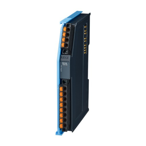
Page 68: Amax-5018 6-Ch Thermocouple Module
±500 mV, ±1 V, ±2.5 V), each channel supports open load detection. The module pro- vides 2000 VDC optical isolation, if any surge voltage or current inputs the channel, the whole system (other modules or control unit) will not be damaged. Figure 4.21 AMAX-5018 Module AMAX-5000 Series User Manual... -
Page 69: Amax-5018 Specification
4.5.1.3 Protection Isolation Voltage: 2000 V 4.5.1.4 Environment Operation Temperature: -25~60°C (vertical mounted) Storage Temperature: -40~85°C Operating Humidity: 20 ~ 95% RH (non-condensing) Storage Humidity: 0 ~ 95% RH (non-condensing) AMAX-5000 Series User Manual... -
Page 70: Led Indicator
Figure 4.22 AMAX-5018 Module LED Indicator Table 4.42: AMAX-5018 Module LED Indicator Color Indication Behavior Green Power on Power Yellow Locating Module EtherCAT Connected Green Blink EtherCAT Connecting Run/Error EtherCAT Abnormal ON/Blink System Abnormal No Error AMAX-5000 Series User Manual... -
Page 71: Pin Definition
4.5.3 Pin Definition Figure 4.23 AMAX-5018 Module Front View Figure 4.24 AMAX-5018 Module Side View AMAX-5000 Series User Manual... -
Page 72: Application Wiring
Table 4.43: Upper 4 Pin Connector Pin Number Pin Definition Table 4.44: Lower 8 Pin Connector Pin Number Pin Definition 4.5.4 Application Wiring Figure 4.25 Wiring for AMAX-5018 AMAX-5000 Series User Manual... -
Page 73: Amax-5018 Object Dictionary
If selecting voltage input range: AIn_Scale = Round (Measured voltage x 10000). (E.g. 3.45678 mV -> 34568) If selecting thermocouple input range: AIn_Scale = Round (Measured temperature x 10). (10.26°C -> 103) AMAX-5000 Series User Manual... - Page 74 +/-50 mV 0x101 +/-100 mV 0x102 +/-500 mV 0x104 +/-1 V 0x140 +/-2.5 V 0x141 K 0~1370°C 0x420 J 0~760°C 0x400 E 0~1000°C 0x460 T -100~400°C 0x440 R 500~1750°C 0x480 S 500~1750°C 0x4A0 B 500~1800°C 0x4C0 AMAX-5000 Series User Manual...
- Page 75 PDO assignment (0x1C10 – 0x1C13) Table 4.54: SM3, PDO assignment 0x1C13 (not changeable) Index Size (byte.bit) Name PDO content 60n0:01 AIn_BurnOut; 60n0:02AIn_OverRange; Analog Input Channel n pro- 0x1A0n 10.0 60n0:03AIn_UnderRange; cess data mapping 60n0:11AIn_Raw; 60n0:13AIn_Scale (n=0~5 for ch0~5) AMAX-5000 Series User Manual...
-
Page 76: Amax-5024 4-Ch Analog Output Module
(other modules or control unit) will not be damaged. Figure 4.26 AMAX-5024 Module 4.6.1 AMAX-5024 Specification 4.6.1.1 General Certification: CE, FCC class A Protocol: EtherCAT Baud Rate: 100M bps Weight: Approx. 80g AMAX-5000 Series User Manual... -
Page 77: Led Indicator
Figure 4.27 AMAX-5024 Module LED Indicator Table 4.55: AMAX-5024 Module LED Indicator Color Indication Behavior Green Power on Power Yellow Locating Module EtherCAT Connected Green Blink EtherCAT Connecting Run/Error EtherCAT Abnormal ON/Blink System Abnormal No Error AMAX-5000 Series User Manual... -
Page 78: Pin Definition
4.6.3 Pin Definition Figure 4.28 AMAX-5024 Module Front View Figure 4.29 AMAX-5024 Module Side View AMAX-5000 Series User Manual... -
Page 79: Application Wiring
Table 4.58: Input Data (0x6000 - 0x6FFF) Index (hex) Name Meaning Data type Flags Default value Detect whether the input 60n0:01 AOn_BurnOut BOOL 0x00 (0 Dec) circuit open 0x0000 (0 60n0:11 Read analog output value UINT Dec) (n=0~3 for ch0~3) AMAX-5000 Series User Manual... - Page 80 For the range ± 5 V: × 10 ) 65536 For the range ± 10 V: × 20 ) 65536 For the range 4 ~ 20 mA: × 16 ) + 4 65536 For the range 0~20 mA: × 20 65536 AMAX-5000 Series User Manual...
- Page 81 Table 4.62: Slew Rate Setting Slew Rate Value (UINT) +/-1 V(mA) /s 0x01 +/-2 V(mA) /s 0x02 +/-4 V(mA) /s 0x04 +/-8 V(mA) /s 0x08 +/-16 V(mA) /s 0x10 +/-32 V(mA) /s 0x20 +/-64 V(mA) /s 0x40 AMAX-5000 Series User Manual...
- Page 82 (n=0~3 for ch0~3) Table 4.66: SM3, PDO assignment 0x1C13 (not changeable) Index Size (byte.bit) Name PDO content Read Analog Output Channel n 60n0:01 AOn_BurnOut; 0x1A0n process data mapping 60n0:11 AOn (n=0~3 for ch0~3) AMAX-5000 Series User Manual...
-
Page 83: Chapter 5 Digital Module
Chapter Digital Module... -
Page 84: Amax-5051 8-Ch Digital Input Module
Connector: Pluggable 4P+8P push-in terminal (#24~16 AWG) Enclosure: PC Power Consumption: 2W @ 24V Protocol: EtherCAT Transmission Rate: 100Mbps Distributed Clock: Default not supported LED Indicator: PWR, RUN, DI status Weight: Approx. 80g AMAX-5000 Series User Manual... -
Page 85: Led Indicator
Relative Humidity: 5~95% (non-condensing) 5.1.2 LED Indicator Figure 5.2 AMAX-5051 Module LED Indicator Table 5.1: AMAX-5051 Module LED Indicator Color Indication Behavior Power Green Power on Green EtherCAT connection Green Blink When TX/RX data in transmission AMAX-5000 Series User Manual... -
Page 86: Pin Definition
Dry/Wet Logic "1" DI0~7 Green Dry/Wet Logic "0" 5.1.3 Pin Definition Figure 5.3 AMAX-5051 Module Front View AMAX-5000 Series User Manual... - Page 87 Figure 5.4 AMAX-5051 Module Side View Table 5.2: Upper 4 Pin Connector Pin Number Pin Definition DI_COM DI_COM Iso. GND Iso. GND Table 5.3: Lower 8 Pin Connector Pin Number Pin Definition AMAX-5000 Series User Manual...
-
Page 88: Application Wiring
PDO assignment (0x1C10 – 0x1C13) Table 5.5: SM0, PDO assignment 0x1C10 (not changeable) Index Size (byte.bit) Name PDO content 3001:01 DI0; 3001:02 DI1; 3001:03 DI2; 3001:04 DI3; 0x1A00 Digital Input 3001:05 DI4; 3001:06 DI5; 3001:07 DI6; 3001:08 DI7 AMAX-5000 Series User Manual... -
Page 89: Amax-5052 16-Ch Digital Input Module
Connector: Pluggable 6P+12P push-in terminal (#28~16 AWG) Enclosure: PC Power Consumption: 2W @ 24V Protocol: EtherCAT Transmission Rate: 100Mbps Distributed Clock: Default not supported LED Indicator: PWR, RUN Weight: Approx. 80g AMAX-5000 Series User Manual... -
Page 90: Led Indicator
Table 5.6: AMAX-5052Module LED Indicator Color Indication Behavior Power Green Power on Green EtherCAT connection Green Blink When TX/RX data in transmission Dry/Wet Logic "1" DI0~7 Green Dry/Wet Logic "0" Dry/Wet Logic "1" DI8~15 Yellow Dry/Wet Logic "0" AMAX-5000 Series User Manual... -
Page 91: Pin Definition
5.2.3 Pin Definition Figure 5.8 AMAX-5052 Module Front View Figure 5.9 AMAX-5052 Module Side View AMAX-5000 Series User Manual... -
Page 92: Application Wiring
Table 5.7: Upper 6 Pin Connector Pin Number Pin Definition DI_COM Iso. GND Table 5.8: Lower 12 Pin Connector Pin Number Pin Definition DI10 DI11 DI12 DI13 DI14 DI15 5.2.4 Application Wiring Figure 5.10 Wiring for AMAX-5052 AMAX-5000 Series User Manual... -
Page 93: Amax-5052 Object Dictionary
PDO content 3001:01 DI0; 3001:02 DI1; 3001:03 DI2; 3001:04 DI3; 3001:05 DI4; 3001:06 DI5; 3001:07 DI6; 3001:08 DI7; 0x1A00 Digital Input 3002:01 DI8; 3002:02 DI9; 3002:03 DI10; 3002:04 DI11; 3002:05 DI12; 3002:06 DI13; 3002:07 DI14; 3002:08 DI15 AMAX-5000 Series User Manual... -
Page 94: Amax-5056 8-Ch Sink-Type Digital Output Module
Connector: Pluggable 4P+8P push-in terminal (#24~16 AWG) Enclosure: PC Power Consumption: 2W @ 24V Protocol: EtherCAT Transmission Rate: 100Mbps Distributed Clock: Default not supported LED Indicator: PWR, RUN, DO status Weight: Approx. 80g AMAX-5000 Series User Manual... -
Page 95: Led Indicator
Figure 5.12 AMAX-5056 Module LED Indicator Table 5.11: AMAX-5056 Module LED Indicator Color Indication Behavior Power Green Power on Green EtherCAT connection Green Blink When TX/RX data in transmission DO turn on DO0~7 Green DO turn off AMAX-5000 Series User Manual... -
Page 96: Pin Definition
5.3.3 Pin Definition Figure 5.13 AMAX-5056 Module Front View Figure 5.14 AMAX-5056 Module Side View AMAX-5000 Series User Manual... -
Page 97: Application Wiring
Table 5.12: Upper 4 Pin Connector Pin Number Pin Definition PCOM PCOM Iso. GND Iso. GND Table 5.13: Lower 8 Pin Connector Pin Number Pin Definition 5.3.4 Application Wiring Figure 5.15 Wiring for AMAX-5056 AMAX-5000 Series User Manual... -
Page 98: Amax-5056 Object Dictionary
PDO assignment (0x1C10 - 0x1C13) Table 5.15: SM0, PDO assignment 0x1C10 (not changeable) Index Size (byte.bit) Name PDO content 3101:01 DO0; 3101:02 DO1; 3101:03 DO2; 3101:04 DO3; 0x1600 Digital Output 3101:05 DO4; 3101:06 DO5; 3101:07 DO6; 3101:08 DO7 AMAX-5000 Series User Manual... -
Page 99: Amax-5056So 8-Ch Source-Type Digital Output Module
Connector: Pluggable 4P+8P push-in terminal (#24~16 AWG) Enclosure: PC Power Consumption: 2W @ 24V Protocol: EtherCAT Transmission Rate: 100Mbps Distributed Clock: Default not supported LED Indicator: PWR, RUN, DO status Weight: Approx. 80g AMAX-5000 Series User Manual... -
Page 100: Led Indicator
Figure 5.17 AMAX-5056SO Module LED Indicator Table 5.16: AMAX-5056SO Module LED Indicator Color Indication Behavior Power Green Power on Green EtherCAT connection Green Blink When TX/RX data in transmission DO turn on DO0~7 Green DO turn off AMAX-5000 Series User Manual... -
Page 101: Pin Definition
5.4.3 Pin Definition Figure 5.18 AMAX-5056SO Module Front View Figure 5.19 AMAX-5056SO Module Side View AMAX-5000 Series User Manual... -
Page 102: Application Wiring
Table 5.17: Upper 4 Pin Connector Pin Number Pin Definition Iso. GND Iso. GND Table 5.18: Lower 8 Pin Connector Pin Number Pin Definition 5.4.4 Application Wiring Figure 5.20 Wiring for AMAX-5056SO AMAX-5000 Series User Manual... -
Page 103: Amax-5056So Object Dictionary
PDO assignment (0x1C10 - 0x1C13) Table 5.20: SM0, PDO assignment 0x1C10 (not changeable) Index Size (byte.bit) Name PDO content 3101:01 DO0; 3101:02 DO1; 3101:03 DO2; 3101:04 DO3; 0x1600 Digital Output 3101:05 DO4; 3101:06 DO5; 3101:07 DO6; 3101:08 DO7 AMAX-5000 Series User Manual... -
Page 104: Amax-5057 16-Ch Sink-Type Digital Output Module
Connector: Pluggable 6P+12P push-in terminal (#28~16 AWG) Enclosure: PC Power Consumption: 2.5W @ 24V Protocol: EtherCAT Transmission Rate: 100Mbps Distributed Clock: Default not supported LED Indicator: PWR, RUN Weight: Approx. 80g AMAX-5000 Series User Manual... -
Page 105: Led Indicator
Table 5.21: AMAX-5057 Module LED Indicator Color Indication Behavior Power Green Power on Green EtherCAT connection Green Blink When TX/RX data in transmission DO turn on DO0~7 Green DO turn off DO turn on DO8~15 Yellow DO turn off AMAX-5000 Series User Manual... -
Page 106: Pin Definition
5.5.3 Pin Definition Figure 5.23 AMAX-5057 Module Front View Figure 5.24 AMAX-5057 Module Side View AMAX-5000 Series User Manual... -
Page 107: Application Wiring
Table 5.22: Upper 6 Pin Connector Pin Number Pin Definition PCOM Iso. GND Table 5.23: Lower 12 Pin Connector Pin Number Pin Definition DO10 DO11 DO12 DO13 DO14 DO15 5.5.4 Application Wiring Figure 5.25 Wiring for AMAX-5057 AMAX-5000 Series User Manual... -
Page 108: Amax-5057 Object Dictionary
3101:04 DO3; 3101:05 DO4; 3101:06 DO5; 3101:07 DO6; 3101:08 DO7; 0x1600 Digital Output 3102:01 DO8; 3102:02 DO9; 3102:03 DO10; 3102:04 DO11; 3102:05 DO12; 3102:06 DO13; 3102:07 DO14; 3102:08 DO15 (DO8-15 mapping to 0x1A01(SM1) before revision number: 0x00000002) AMAX-5000 Series User Manual... -
Page 109: Amax-5057So 16-Ch Source-Type Digital Output Module
Connector: Pluggable 6P+12P push-in terminal (#28~16 AWG) Enclosure: PC Power Consumption: 2.5W @ 24V Protocol: EtherCAT Transmission Rate: 100Mbps Distributed Clock: Default not supported LED Indicator: PWR, RUN Weight: Approx. 80g AMAX-5000 Series User Manual... -
Page 110: Led Indicator
Table 5.26: AMAX-5057SO Module LED Indicator Color Indication Behavior Power Green Power on Green EtherCAT connection Green Blink When TX/RX data in transmission DO turn on DO0~7 Green DO turn off DO turn on DO8~15 Yellow DO turn off AMAX-5000 Series User Manual... -
Page 111: Pin Definition And Wiring
5.6.3 Pin Definition and Wiring Figure 5.28 AMAX-5057SO Module Front View Figure 5.29 AMAX-5057SO Module Side View AMAX-5000 Series User Manual... -
Page 112: Application Wiring
Table 5.27: Upper 6 Pin Connector Pin Number Pin Definition Iso. GND Table 5.28: Lower 12 Pin Connector Pin Number Pin Definition DO10 DO11 DO12 DO13 DO14 DO15 5.6.4 Application Wiring Figure 5.30 Wiring for AMAX-5057SO AMAX-5000 Series User Manual... -
Page 113: Amax-5057So Object Dictionary
3101:04 DO3; 3101:05 DO4; 3101:06 DO5; 3101:07 DO6; 3101:08 DO7; 0x1600 Digital Output 3102:01 DO8; 3102:02 DO9; 3102:03 DO10; 3102:04 DO11; 3102:05 DO12; 3102:06 DO13; 3102:07 DO14; 3102:08 DO15 (DO8-15 mapping to 0x1A01(SM1) before revision number: 0x00000002) AMAX-5000 Series User Manual... - Page 114 AMAX-5000 Series User Manual...
-
Page 115: Chapter 6 Counter/Encoder Module
Chapter Counter/Encoder Module... -
Page 116: Amax-5080 2-Ch Counter/ Encoder 32-Bit
Mode and Bi-direction Mode. It supports up to 1MHz input frequency. The module provides 2000 VDC optical isolation, if any high voltage or current damage the chan- nels, the whole system (other modules or control unit) will not be damaged. Figure 6.1 AMAX-5080 Module AMAX-5000 Series User Manual... -
Page 117: Amax-5080 Specification
Logic 1: 11…30 V (EN 61131-2, type 3) Input Frequency: 1 MHz max. 6.1.1.3 Protection Isolation Voltage: 2,000V 6.1.1.4 Environment Operation Temperature: -25~60°C (vertical mounted) Storage Temperature: -40~85°C Relative Humidity: 5~95% (non-condensing) AMAX-5000 Series User Manual... -
Page 118: Led Indicator
Green Blink EtherCAT Connecting Run/Error EtherCAT Abnormal ON/Blink System Abnormal No Error Green Signal Input Green Signal Input Green Signal Input Green Signal Input Green Signal Input Green Signal Input Green Signal Input Green Signal Input AMAX-5000 Series User Manual... -
Page 119: Pin Definition
6.1.3 Pin Definition Figure 6.3 AMAX-5080 Module Front View Figure 6.4 AMAX-5080 Module Side View AMAX-5000 Series User Manual... -
Page 120: Application Wiring
Table 6.3: Lower 12 Pin Connector Pin Number Pin Definition Ch0 L+ Ch0 L- Ch1 A+ Ch1 A- Ch1 B+ Ch1 B- Ch1 Z+ Ch1 Z- Ch1 L+ Ch1 L- 6.1.4 Application Wiring Figure 6.5 Wiring for AMAX-5080 AMAX-5000 Series User Manual... -
Page 121: Circuit Layout
Encoder Mode Bi-Direction Mode Both modes support the following features: Overflow/underflow detection and reload counter Latch counter value Reset counter value Set counter value Counter frequency measurement Input Filter AMAX-5000 Series User Manual... - Page 122 Blue are 0x6000, 0x7000, 0x8000 parameters. Red are external signals. n=0~1 for Ch0~1 The counter value and A, B phase status can be read at below Index: Table 6.4: Encoder Mode parameter index Name Index CIn_Counter_Value 0x60n0:11 CIn_Status_of_Input_A 0x60n0:09 CIn_Status_of_Input_B 0x60n0:0A AMAX-5000 Series User Manual...
- Page 123 Blue are 0x6000, 0x7000, 0x8000 parameters. Red are external signals. n=0~1 for Ch0~1 The counter value and A, B signal input status can be read below: Table 6.5: Bi-Direction Mode parameter index Name Index CIn_Counter_Value 0x60n0:11 CIn_Status_of_Input_A 0x60n0:09 CIn_Status_of_Input_B 0x60n0:0A AMAX-5000 Series User Manual...
-
Page 124: Counter Features
The figure below shows an example of overflow/underflow behavior under Bi-direc- tion Mode, the same behavior also applies for Encoder Mode. Figure 6.9 Counter Overflow and Underflow Blue are 0x6000, 0x7000, 0x8000 parameters. Red are external signals. n=0~1 for Ch0~1 AMAX-5000 Series User Manual... - Page 125 COn_Enable_Latch_Z COn_Enable_Latch_External Enable Latch (0x70n0:02) (0x70n0:03) CIn_Latch_Z_Valid CIn_Latch_External_Valid Enable Latch Valid (0x60n0:02) (0x60n0:03) Cn_Z_Pulse_Active_Polarity Cn_External_Latch_Active_Polarity Active Polarity (0x80n0:03) (0x80n0:05) CIn_Status_of_Input_Z CIn_Status_of_Input_External_Latch Status (0x60n0:0C) (0x60n0:11) * Active Polarity: 0: Rising Edge, 1: Falling Edge n=0~1 for Ch0~1 AMAX-5000 Series User Manual...
- Page 126 Figure 6.10 Latch Counter by Z pin Blue are 0x6000, 0x7000, 0x8000 parameters. Red are external signals. Note! CI0_Latch_Values(0x6000:12) can be overwritten by both Z and L pin if those pins are configured correctly. AMAX-5000 Series User Manual...
- Page 127 Step1: Set C0_Enable_Z_Pulse_Reset (0x8000:02) to “1”. Step2: Set COn_Enable_Latch_Z (0x70n0:02) to "1" Step3: An external reset signal (Rising edge-triggered) at Z pin will clear both CIn_Counter_Value (0x6000:11) and CIn_Latch_Values (0x600n0:12) Figure 6.11 Reset Counter by Z pin AMAX-5000 Series User Manual...
- Page 128 The counter value should not be set over Reload Counter Value. 6.1.7.5 Counter Frequency Measurement The increment (or decrement) frequency of counter value can be read by CIn_Fre- quency_Value (0x60n0:13), the value will be updated every second. This feature is often used to determine velocity. AMAX-5000 Series User Manual...
-
Page 129: Amax-5080 Object Dictionary
BOOL 0x00 put_Z CIn_Status_of_In- 60n0:0C Status of input L BOOL 0x00 put_External_Latch 60n0:11 CIn_Counter_Value Counter Value UDINT 0x00 60n0:12 CIn_Latch_Value Latch Value UDINT 0x00 CIn_Frequen- Update Frequency 60n0:13 UDINT 0x00 cy_Value every second (n=0~1 for Ch0~1) AMAX-5000 Series User Manual... - Page 130 Enable the register Cn_Enable_Regis- change of reload counter 80n0:06 UINT 0x00 ter_Reload 0: Disable 1: Enable Cn_Re- 0xFFFFF 80n0:07 load_Counter_Val- Reload counter value UDINT Cn_Input_Filter_- 0x00 80n0:08 Input Filter Time UINT Time (Disable) (n=0~1 for Ch0~1) AMAX-5000 Series User Manual...
- Page 131 MCU FW version is 255 (Dec). 0xF600:0A Alarm Status 0x02: Encoder MCU is ready, BIT8 0x00 but Firmware version is not between 100~254 (Dec.) 0x03: Encoder MCU is in boot mode, please upgrade firmware. AMAX-5000 Series User Manual...
- Page 132 Table 6.16: SM3, PDO assignment 0x1C13 (not changeable) Index Size (byte.bit) Name PDO content 60n0:01CIn_Set_Counter_Done; 60n0:02CIn_Latch_Z_Valid; 60n0:03CIn_Latch_External_Valid; 60n0:04CIn_Over_Flow; 60n0:05CIn_Under_Flow; 60n0:09CIn_Status_of_Input_A; ENC Input Channel n 0x1A0n 14.0 60n0:0ACIn_Status_of_Input_B; process data mapping 60n0:0BCIn_Status_of_Input_Z; 60n0:0CCIn_Status_of_Input_Exter- nal_Latch; 60n0:11CIn_Counter_Value; 60n0:12CIn_Latch_Value; 60n0:13CIn_Frequency_Value (n=0~1 for ch0~1) AMAX-5000 Series User Manual...
-
Page 133: Amax-5081 1-Ch Ttl/Rs-422 Encoder/Counter Module
TTL or RS422 differential input with up to 10MHz input frequency. The module provides 2000 VDC optical isolation, if any high voltage or current dam- age the channels, the whole system (other modules or control unit) will not be dam- aged. Figure 6.13 AMAX-5081 Module AMAX-5000 Series User Manual... -
Page 134: Amax-5081 Specification
Logic 0: 0.8 V max. Logic 1: 2.0 V min. (5.25 V max.) 6.2.1.5 Protection Isolation Voltage: 2,000V 6.2.1.6 Environment Operation Temperature: -25~60°C (vertical mounted) Storage Temperature: -40~85°C Relative Humidity: 5~95% (non-condensing) AMAX-5000 Series User Manual... -
Page 135: Led Indicator
Locating Module EtherCAT Connected Green Blink EtherCAT Connecting Run/Error EtherCAT Abnormal ON/Blink System Abnormal No Error Green Encoder Signal Input Green Encoder Signal Input Green Encoder Signal Input Green Latch Input Green Compare Output/ Pulse Output AMAX-5000 Series User Manual... - Page 136 6.2.3 Pin Definition Figure 6.15 AMAX-5081 Module Front View Figure 6.16 AMAX-5081 Module Side View AMAX-5000 Series User Manual...
- Page 137 Table 6.18: Upper 4 Pin Connector Pin Number Pin Definition ISO.GND PULSE_OUT ISO.GND Table 6.19: Lower 8 Pin Connector Pin Number Pin Definition LATCH ISO.GND 6.2.4 Application Wiring Figure 6.17 Wiring for AMAX-5081 AMAX-5000 Series User Manual...
- Page 138 6.2.5 Circuit Layout 6.2.5.1 Encoder Input Figure 6.18 AMAX-5081 Encoder Differential Input Figure 6.19 AMAX-5081 Encoder Single-Ended Input 6.2.5.2 Latch Input Figure 6.20 AMAX-5081 Latch Input AMAX-5000 Series User Manual...
- Page 139 The supported features for each mode are listed below: Features Encoder x4 Pulse/Dir. CW/CCW Pulse/Gate Pulse Train Output Overflow/underflow detection Latch counter value Reset counter value Set counter value Input filter Position compare output Reversion of A/B phase input Frequency mea- surement AMAX-5000 Series User Manual...
- Page 140 0x1602 for SM2 and 0x1A02 for SM3. In this way, the related PDO will be added. Fig- ures below show how PDO should be assigned on CODESYS when using the com- pare output. Figure 6.22 PDO assignment for SM2 - CODESYS interface Figure 6.23 PDO assignment for SM3 – CODESYS interface AMAX-5000 Series User Manual...
- Page 141 The counter direction can be reversed by setting the Reversion_Of_Rotation (0x8000:06), the following table is the list of all Encoder x4 mode related parameters. Table 6.20: Encoder x4 Mode parameter index Name Index Counter_Value 0x6000:11 Status_of_Input_A 0x6000:09 Status_of_Input_B 0x6000:0A Reversion_Of_Rotation 0x8000:06 AMAX-5000 Series User Manual...
- Page 142 Below figure shows the counter behavior of CW/CCW mode. Ch_A and Ch_B are the pulse from encoder or any pulse generator. The counter value counts up with the pulse Ch_A and counts down with the pulse Ch_B. Figure 6.26 Encoder Mode – CW/CCW AMAX-5000 Series User Manual...
- Page 143 Gate is active, the counter keeps the same value. The activate polarity of Ch_B can be modified by the parameter Z_And_Gate_Ac- tive_Polarity (0x8000:03). Figure 6.27 Encoder Mode – Pulse/Gate Blue are the 0x6000, 0x7000, 0x8000 parameters. Red are the external signals. AMAX-5000 Series User Manual...
- Page 144 The total number of pulse output can be set by Pulse_Train_Number (0x8000:0D), the number should between 0~2 (0 is continues output). Figure 6.28 Pulse Train Output Blue are the 0x6000, 0x7000, 0x8000 parameters. Red is the output signal. AMAX-5000 Series User Manual...
- Page 145 Over_Flow (0x6000:05) will be set to "1" correspondingly. The figure below shows an example of overflow/underflow behavior under Pulse/Dir. Mode, the same behavior also applies for other Encoder Modes. Figure 6.29 Counter Overflow and Underflow Detection AMAX-5000 Series User Manual...
- Page 146 Step5: Once the Latch_External_Valid (0x6000:02) bit is low, the module is ready for the next latching signal. Figure 6.30 Latch Counter by Z pin Blue are 0x6000, 0x7000, 0x8000 parameters. Red are external signals. All related configurable parameters for Latch Counter are listed below: AMAX-5000 Series User Manual...
- Page 147 Step3: Once counter value is cleared, Latch_Z_Valid (0x6000:01) will be raised to True. Step4: Set Enable_Latch_Z (0x7000:01) to False to clear the flag for next input. * When the reset is done, do the Step1 before next reset signal comes. Figure 6.31 Reset Counter Value AMAX-5000 Series User Manual...
- Page 148 Step3: When the Set_Counter_Done (0x6000:03) is “1”, the counter value is changed Step4: Set_Counter (0x7000:03) should be set to “0” before the next change Step5: Set_Counter_Done (0x6000:03) will be restored to “0” along with Set_Counter. Figure 6.32 Set Counter Value AMAX-5000 Series User Manual...
- Page 149 Step6: Set Set_Position_Compare_Offset_Value (0x7000:12) (0 ~ 232). Step7: Set Position_Compare_Offset (0x7000:09) to “1” to write the offset into the buffer. Step8: Read Set_Position_Compare_Offset_Done (0x6000:06), if the value is “1”, then the offset is written to the buffer successfully. AMAX-5000 Series User Manual...
- Page 150 “0”, then the next offset value can be set to the buffer if needed. Figure 6.33 Set Position Compare Offset Value Please refer to the following flow chart to set the position compare output configura- tion: Figure 6.34 AMAX-5081 Hardware Position Compare Configuration – Flow Chart AMAX-5000 Series User Manual...
- Page 151 Figure 6.35 AMAX-5081 Hardware Position Compare Application – Timing Diagram * Latch Signal can be rising edge or falling edge active (Position_Com- pare_Latch_Polarity (0x8000:08)) ** Pulse_Output can be initial low or initial high (Position_Compare_Output_Polarity (0x8000:09)) AMAX-5000 Series User Manual...
- Page 152 At the moment of the EtherCAT master trigger the AMAX-5081 module by PDO, the module will generate a pre-defined width of pulse after a period of Offset. Please follow the steps below to configure software triggered Position Compare Out- put function. AMAX-5000 Series User Manual...
- Page 153 Step8: Set Position_Compare_Offset (0x7000:09) to “0” when buffer is written. Step9: Read Set_Position_Compare_Offset_Done (0x6000:06) again, if the value is “0”, then the next offset value can be set to the buffer if needed. Figure 6.37 Set Position Compare Offset Value AMAX-5000 Series User Manual...
-
Page 154: Set_Position_Compare_Offset_Value (0X7000:12), The Amax-5081 Pulse_Output
(0x6000:07) will be raise to “1”. Step3: After the pulse output is done, set Enable_Position_Compare (0x7000:0B) to “0” Step4: Check if Enable_Position_Compare_ Done (0x6000:07) is changed to “0” coordinately, and back to step1 for the next compare trigger signal. AMAX-5000 Series User Manual... -
Page 155: Latch Signal Can Be Rising Edge Or Falling Edge Active
Figure 6.39 AMAX-5081 Software Position Compare Application – Timing Diagram Chart * Latch Signal can be rising edge or falling edge active (Position_Com- pare_Latch_Polarity (0x8000:08)) ** Pulse_Output can be initial low or initial high (Position_Compare_Output_Polarity (0x8000:09)) AMAX-5000 Series User Manual... - Page 156 Select input source ChA or ChB on Frequency_Measure_Input_Select (0x8000:05) The input pulse frequency will be showed on Frequency_Value (0x6002:01), the value will be updated every second. This feature is often used to determine motor velocity. AMAX-5000 Series User Manual...
- Page 157 The TxPDO toggle is tog- gled by the slave when 0x6000:10 TxPDO_Toggle BOOL 0x00 the data of the associated TxPDO is updated. 0x6000:11 Counter_Value Counter Value UDINT 0x00 0x6000:12 Latch_Value Latch Value UDINT 0x00 AMAX-5000 Series User Manual...
- Page 158 Set Counter Value UDINT 0x00 set_Value 6.2.8.5 Pulse Train Output Status (0x7001) Table 6.30: Pulse Train Output Status (0x7001) Index (hex) Name Meaning Data type Flags Default value Enable_- Enable Pulse Train 0x7001:01 BOOL 0x00 Pulse_Train_Output Output AMAX-5000 Series User Manual...
-
Page 159: 0X8000:09
Position_Com- Compare Output Positive 0x0007A 0x8000:0A UINT pare_Output_Width Width Pulse_Train_Pos_ Pulse Train Positive Width 0x00018 0x8000:0B UDINT Width (50ns) Pulse_Train_Neg_ Pulse Train Negative Width 0x00018 0x8000:0C UINT Width (50ns) Pulse_Train_Num- 0x00000 0x8000:0D Pulse Train Number UINT AMAX-5000 Series User Manual... - Page 160 Encoder FPGA Firm- 0xF600:09 BIT8 0x00 ware Version ware Version AMAX-5081 Alarm 0xF600:0A Alarm Status BIT8 0x00 status F600:0A is System Alarm Status 0x00: Normal 0x01: Encoder FPGA is not Ready.(FPGA Firmware Version is 0x00 or 0xFF) AMAX-5000 Series User Manual...
- Page 161 0x1600 ~ 0x1604 are mutually exclusive, the control mode should align with 0x1C13. Table 6.34: SM3, PDO assignment 0x1C13 (selectable) Index Size (byte.bit) Name PDO content 0x6000:03Set_Counter_Done 0x6000:04Under_Flow 0x6000:05Over_Flow 0x6000:09Status_of_Input_A 0x6000:0AStatus_of_Input_B 0x1A00 6.0 Position Measure Status 0x6000:0BStatus_of_Input_Z 0x6000:0DStatus_of_External_Latch 0x1C32:20Sync_Error 0x6000:10TxPDO_Toggle 0x6000:11Counter_Value AMAX-5000 Series User Manual...
- Page 162 0x1A03 6.0 Pulse Gate Status 0x6000:0BStatus_of_Input_Z; 0x6000:0DStatus_of_External_Latch; 0x1C32:20Sync_Error; 0x6000:10TxPDO_Toggle; 0x6000:11Counter_Value 0x6001:01Enable_Pulse_Train_Out- 0x1A04 2.0 Pulse Train Status put_Done 0x1A05 4.0 Frequency Status 0x6002:01Frequency_Value *Note: 0x1A00 ~ 0x1A04 are mutually exclusive, the control mode should align with 0x1C12. AMAX-5000 Series User Manual...
- Page 163 Chapter Digital I/O Module with Timestamp...
- Page 164 Even though the time difference is smaller than a cycle time, it can be crit- ical especially on the application which needs synchronized signal output. Figure 7.2 Standard Digital Output Module (SM mode) AMAX-5000 Series User Manual...
- Page 165 The Continuous mode will continuously update the latest timestamp of state change. Each rising-edge (th) and falling-edge (tl) can be set to Single Event mode or Contin- uous mode independently. AMAX-5000 Series User Manual...
- Page 166 Figure 7.4 Digital Input with Timestamp - Single Event Mode Figure 7.5 Digital Input with Timestamp - Continuous Mode AMAX-5000 Series User Manual...
- Page 167 Enabling the precise and deterministic IO responses. Releasing the data process from cycle base to time base, increasing the flexibil- ity of cycle time of whole system. Reduces processor loading by reducing the data acquisition frequency. AMAX-5000 Series User Manual...
- Page 168 LED to indicate digital status. The module provides 2,000 VDC optical isolation between channels. If any high voltage or current damage the channels, the whole system (other modules, and control unit) won't be affected because it is already isolated. Figure 7.7 AMAX-5051T Module AMAX-5000 Series User Manual...
- Page 169 Input Delay: < 10us Typical Input Current: Logic level 1: 1.4mA~4.3mA (11V~30V) 7.2.1.4 Protection Isolation Voltage: 2,000V 7.2.1.5 Environment Operation Temperature: -25~60°C (vertical mounted) Storage Temperature: -40~85°C Relative Humidity: 5~95% (non-condensing) AMAX-5000 Series User Manual...
- Page 170 Table 7.1: AMAX-5051T Module LED Indicator Color Indication Behavior Power Green Power on Green EtherCAT connection Run/Error Green Blink When TX/RX data in transmission Wet Logic “1” T0~1 Green (timestamp) Wet Logic “0” Dry/Wet Logic “1” DI2~7 Green Dry/Wet Logic “0” AMAX-5000 Series User Manual...
- Page 171 7.2.3 Pin Definition Figure 7.9 AMAX-5051T Module Front View Figure 7.10 AMAX-5051T Module Side View AMAX-5000 Series User Manual...
- Page 172 Table 7.2: Upper 4 Pin Connector Pin Number Pin Definition DI_COM_TS DI_COM Iso.GND Iso.GND Table 7.3: Lower 8 Pin Connector Pin Number Pin Definition DI0_TS DI1_TS 7.2.4 Application Wiring Figure 7.11 Wiring for AMAX-5051T standard DI AMAX-5000 Series User Manual...
- Page 173 The statuses are displayed only in one EtherCAT cycle, the read of LatchPos and LatchNeg resets the status 0/1. LatchPos0/1: The LatchPos0/1 is the time of the first/last rising edge, depending on the setting of SingleEventMode or ContinuousMode. AMAX-5000 Series User Manual...
- Page 174 Table 7.6: SM0, PDO assignment 0x1C10 (selectable) Index Size (byte.bit) Name PDO content 0x1A14 SysTime SysTime 0x1A15 SysTime SysTime 0x1A0n Channel n (n=0~0 for ch0~7) Note! 0x1A14 and 0x1A15 are mutually exclusive 0x1A0n are not changeable AMAX-5000 Series User Manual...
- Page 175 System SysTime 0x1A15 System SysTime Note! 0x1A10 ~ 0x1A13 are mutually exclusive, it can only be selected either SM1 or SM2. 0x1A14 ~ 0x1A15 are mutually exclusive, it can only be selected either SM1 or SM2. AMAX-5000 Series User Manual...
- Page 176 Connector: Pluggable 4P+8P push-in terminal (#24~16 AWG) Enclosure: PC Power Consumption: 2W @ 24V Protocol: EtherCAT Transmission Rate: 100Mbps LED Indicator: PWR, RUN, DO status Weight: Approx. 80g AMAX-5000 Series User Manual...
- Page 177 Figure 7.14 AMAX-5056T Module LED Indicator Table 7.9: AMAX-5056T Module LED Indicator Color Indication Behavior Power Green Power on Green EtherCAT connection Run/Error Green Blink When TX/RX data in transmission Wet Logic “1” T0~1 Green (timestamp) Wet Logic “0” AMAX-5000 Series User Manual...
- Page 178 7.3.3 Pin Definition Figure 7.15 AMAX-5056T Module Front View Figure 7.16 AMAX-5056T Module Side View AMAX-5000 Series User Manual...
- Page 179 Table 7.10: Upper 4 Pin Connector Pin Number Pin Definition PCOM PCOM Iso.GND Iso.GND Table 7.11: Lower 8 Pin Connector Pin Number Pin Definition DO0_TS DO1_TS 7.3.4 Application Wiring Figure 7.17 Wiring for AMAX-5056T timestamp DI AMAX-5000 Series User Manual...
- Page 180 Table 7.17: SM2, PDO assignment 0x1C12 (not changeable) Index Size (byte.bit) Name PDO content 0x160n Channel n (n=0~1 for ch0~1) Table 7.18: SM3, PDO assignment 0x1C13 (selectable) Index Size (byte.bit) Name PDO content 0x1A00 SysTime SysTime AMAX-5000 Series User Manual...
- Page 181 AMAX-5000 Series User Manual...
- Page 182 No part of this publication may be reproduced in any form or by any means, such as electronically, by photocopying, recording, or otherwise, without prior written permission from the publisher. All brand and product names are trademarks or registered trademarks of their respective companies. © Advantech Co., Ltd. 2021...
Need help?
Do you have a question about the AMAX-5000 Series and is the answer not in the manual?
Questions and answers