Table of Contents
Advertisement
Quick Links
Advertisement
Table of Contents

Related Manuals for Advantech ADAM-6156PN


Summary of Contents for Advantech ADAM-6156PN
- Page 1 User Manual ADAM-6100PN Series PROFINET I/O Modules...
- Page 2 No part of this manual may be reproduced, copied, translated or transmitted in any form or by any means without the prior written permission of Advantech Co., Ltd. Information provided in this manual is intended to be accurate and reliable. How- ever, Advantech Co., Ltd.
- Page 3 This product has passed the CE test for environmental specifications when shielded cables are used for external wiring. We recommend the use of shielded cables. This kind of cable is available from Advantech. Please contact your local supplier for ordering information.
- Page 4 The sound pressure level at the operator's position according to IEC 704-1:1982 is no more than 70 dB (A). DISCLAIMER: This set of instructions is given according to IEC 704-1. Advantech disclaims all responsibility for the accuracy of any statements contained herein.
-
Page 5: Table Of Contents
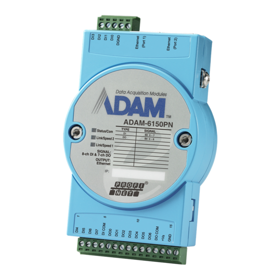
Product Specifications......9 Digital I/O Modules.................. 10 3.1.1 Overview ..................10 Figure 3.1 ADAM-6150PN ............10 Figure 3.2 ADAM-6151PN ............11 Figure 3.3 ADAM-6156PN ............11 3.1.2 Specifications................12 3.1.3 Switch Settings ................13 3.1.4 Application Wiring ............... 14 Relay Modules ..................16 3.2.1... - Page 6 Chapter ............23 Chapter ............23 Chapter ............23 Chapter ............23 Chapter ............23 System Hardware Configuration ............24 4.1.1 System Requirements ............... 24 4.1.2 Communication Interface............24 Install ADAM.NET Utility Software ............24 ADAM.NET Utility Overview..............24 4.3.1 ADAM.NET Utility Operation Window.........
-
Page 7: Chapter 1 Overview
Chapter Overview... -
Page 8: Introduction
DIP switch on the side of ADAM module. Refer to Section 1.3.3 for how to configure it. When you configure the mode as Initial mode, you can configure ADAM-6100PN module's IP address and related setting by Advantech APAX/ ADAM.Net utility. When you configure the mode as Normal mode, ADAM-6100PN modules are ready to communicate with PROFINET master by PROFINET protocol. -
Page 9: Features
Features 1.3.1 Daisy Chain Connection ADAM-6100PN module has built in Ethernet switches to allow daisy chain connections in an The two Ether- Ethernet network, making it easier to deploy, and helping improve scalability. net ports are fully compliant with IEEE 802.3u 10/100Mbpst through standard RJ-45 connectors. -
Page 10: 2,500V Isolation Protection
1.3.2 2,500V Isolation Protection With triple isolation, including power supply, input/output, and Ethernet communica- tion, ADAM-6100PN series ensures I/O data to be controlled correctly, and prevents devices from breaking down. 1.3.3 Ethernet-based Configuration Tool You can configure ADAM-6100PN module as Initial mode or Normal mode by the DIP switch in the side of each module. -
Page 11: Status Led Indicator
1.3.4 Status LED Indicator There are 3 LED indicators on the front of the ADAM-6100 module-Status/COM, Link/ Speed 1, and Link/Speed 2. The Status/COM LED indicates the status of the module. The Link/Speed LEDs indicate the network connections of Ethernet port 1 and port 2. After power on, if the module is not connected to any network, the Status LED and the COM LED will keep ON. -
Page 12: Dimensions
1.3.5 Dimensions The following diagrams show the dimensions of the ADAM-6100 modules: Figure 1.2 ADAM-6100 Front Figure 1.3 ADAM-6100 Back ADAM-6100PN Series User Manual... -
Page 13: Figure 1.4 Adam-6100 Side
Figure 1.4 ADAM-6100 Side Figure 1.5 ADAM-6100 Top ADAM-6100PN Series User Manual... - Page 14 ADAM-6100PN Series User Manual...
-
Page 15: Chapter 2 Hardware Installation Guide
Chapter Hardware Installation Guide... -
Page 16: Determining The Proper Environment
Determining the Proper Environment Prior to installing ADAM-6100 modules, please check the following. 2.1.1 Package Contents Unpack the shipped boxes and make sure that the contents include: ADAM-6100 module with one bracket and DIN-rail adapter ADAM-6100 module User Manual ... -
Page 17: Mounting
Mounting ADAM-6100 modules are designed as compact units and are allowed to be installed in the field site under the following methods. 2.2.1 Panel Mounting Each ADAM-6100 Module is packed with a plastic panel mounting bracket. Users can refer the dimensions of the bracket to configure an optimal placement in a panel or cabinet. -
Page 18: Din-Rail Mounting
Figure 2.2 Fix Module on the Bracket 2.2.2 DIN-rail mounting The ADAM-6100 module can also be secured to the cabinet by using mounting rails. Fix the ADAM-6100 module with the DIN-rail adapter as Figure 2-3. Then secure it on the DIN-rail as Figure 2-4. If you mount the module on a rail, you should also con- sider using end brackets at each end of the rail. -
Page 19: Figure 2.3 Fix Module On The Din-Rail Adapter
Figure 2.3 Fix Module on the DIN-rail Adapter Figure 2.4 Secure Module to a DIN-rail ADAM-6100PN Series User Manual... -
Page 20: Wiring & Connections
Wiring & Connections This section provides basic information on wiring the power supply, I/O units, and net- work connection. 2.3.1 Power Supply Wiring Although the ADAM-6100 systems are designed for a standard industrial unregulated 24 V power supply, they accept any power unit that supplies within the range of +10 to +30 V . -
Page 21: I/O Module Wiring
2.3.2 I/O Module Wiring The system uses a plug-in screw terminal block for the interface between I/O mod- ules and field devices. The following information must be considered when connect- ing electrical devices to I/O modules. 1. The terminal block accepts wires from 0.5 mm to 2.5 mm. 2. - Page 22 ADAM-6100PN Series User Manual...
-
Page 23: Chapter 3 Product Specifications
Chapter Product Specifications... -
Page 24: Digital I/O Modules
Digital I/O Modules 3.1.1 Overview The ADAM-6150PN, ADAM-6151PN and ADAM-6156PN are a series of isolated dig- ital I/O modules which support the PROFINET protocol. According to the channel number difference, you can choose the best digital I/O modules for your application. -
Page 25: Figure 3.2 Adam-6151Pn
Figure 3.2 ADAM-6151PN Figure 3.3 ADAM-6156PN ADAM-6100PN Series User Manual... -
Page 26: Specifications
Input Impedance: 10 kΩ Transition Time: 0.2 ms Digital Output Channels: – ADAM-6150PN: 7 – ADAM-6156PN: 16 Output Voltage Range: 8 ~ 35 V Normal Output Current: 100 mA (per channel) FSV Safety Function General ... -
Page 27: Switch Settings
3.1.3 Switch Settings ADAM-6150PN: Switch Position DI Channel Ch3 Dry Contact (Default) Wet contact ADAM-6151PN: Switch Position DI Channel Ch3 Switch Position DI Channel Ch11 Ch10 Ch9 Ch15 Ch14 Ch13 Ch12 Dry Contact (Default) Wet contact ADAM-6100PN Series User Manual... -
Page 28: Application Wiring
3.1.4 Application Wiring Isolated Digital Input - Dry Contact Isolated Digital Input - Wet Contact ADAM-6100PN Series User Manual... - Page 29 Isolated Digital Output (ADAM-6150PN) Isolated Digital Output (ADAM-6156PN) ADAM-6100PN Series User Manual...
-
Page 30: Relay Modules
Relay Modules 3.2.1 Overview The ADAM-6160PN is a relay module which supports PROFINET protocol. It pro- vides 5 Form C and 1 Form A/B (selectable) relay channels and is excellent for ON/ OFF control or low-power switching applications in an PROFINET system. ... -
Page 31: Jumper Settings
General Communication: 10/100 Base-T Ethernet Supported Protocol: PROFINET Power Input: Unregulated 10 ~ 30 V Power Consumption: 3.5 W @ 24 V Power Reversal Protection (30V Max.) Operating Humidity: 20 ~ 95% RH (non-condensing) ... -
Page 32: Analog I/O Modules
Analog I/O Modules 3.3.1 ADAM-6117PN: 8-ch Isolated Analog Input Module 3.3.1.1 Overview The ADAM-6117PN is a 16-bit, 8-channel isolated analog input module. It accepts millivoltage inputs (±150 mV, ±500 mV), voltage inputs (±1 V, ±5 V and ±10 V) and current input (±20 mA, 0~20 mA, 4~20 mA). - Page 33 • Sampling Rate: 12 samples/second (total) • CMR @ 50/60 Hz: 92 dB • NMR @ 50/60 Hz: 60 dB • Span Drift: ±30 ppm/°C • Zero Drift: ±6 μV/°C • Isolation Voltage: 2,500 V • High Common Mode: up to 200 V General: •...
-
Page 34: Adam-6124Pn: 4-Ch Analog Output And 4-Ch Digital Input Module
3.3.2 ADAM-6124PN: 4-ch Analog Output and 4-ch Digital Input Module 3.3.2.1 Overview The ADAM-6124PN is a 12-bit, 4-channel analog output module along with 4-chan- nel dry-contact digital input. It provides programmable output ranges on all channels and supports voltage and current outputs, which makes it an ideal output control solution. - Page 35 3.3.2.2 Specifications Analog Output: • Channels: 4 • Output Type: V, mA • Voltage/Current Range: 5V, 10V, ±5V, ±10V, 0~20mA,4~20 mA (different range can be configured for each channel in the utility) • Resolution: 12-bit • Output Impedance: 2.1Ω • Output Driving Capacity –...
- Page 36 ADAM-6100PN Series User Manual...
-
Page 37: Chapter 4 System Configuration Guide
Chapter System Configuration Guide... -
Page 38: System Hardware Configuration
You can find the Utility installation file in the CD with your ADAM module, or link to the web site: http://www.advantech.com and click into the Download Area under Service & Support site to get the latest version of the ADAM-6100 Series ADAM.NET Utility. -
Page 39: Adam.net Utility Operation Window
4.3.1 ADAM.NET Utility Operation Window After you have successfully installed ADAM.NET Utility, there will be one shortcut icon on the desktop. Double click the shortcut icon that you should be able to see the operation window as Figure 5.1. Figure 4.1 ADAM.NET Utility Operation Window The operation window consists of four areas --- the Menus, the Toolbar, the Module Tree Display Area and the Status Display Area. - Page 40 Modbus/TCP as communication protocol. You can launch the terminal to communicate with ADAM-6000 module by these two protocol directly. DiagAnywhere Searcher - There are multiple Advantech products installed with DiagAnywhere server, which gives user remote control ability through Ethernet.
-
Page 41: Figure 4.2 Adam.net Utility Toolbar
4.3.1.6 Toolbar There are 7 graphical icons on the toolbar for 7 common used options of Menus. Fig- ure 5.2 below shows definition for each graphical icon. Print Screen Monitor Stream/Event Data Terminal for Command Testing Add Devices to Group Search Modules Save Favorite Group Open Favorite Group... -
Page 42: Search Adam-6100 Modules
You can see the Firmware Version on the selected ADAM-6100 module in this tab. You can also update the firmware by clicking Download button. The latest firmware for ADAM-6100 modules is available on Advantech website: http://www.advan- tech.com ADAM-6100PN Series User Manual... - Page 43 4.3.2.2 Setting You can change IP Address, Subnet Address, and Default Gateway of selected ADAM-6100 module in this tab. You can also enable or disable DHCP function for ADAM-6100 module. ADAM-6100PN Series User Manual...
-
Page 44: I/O Module Configuration
4.3.3 I/O Module Configuration After you have completed all general configuration of ADAM-6000 module described in previous section, then you need to configure setting for input and output channel such as channel range, calibration and alarm. At the same time, you can see input channel value and set value of output channel in the Status Display area of utility. -
Page 45: Figure 4.4 Channels Range Configuration Area
4.3.3.1 All Channel Configuration For these ADAM-6000 modules, when you click the All Channel Configuration item in the Module Tree Display area, there will be four parts on the Status Display area. In the top left-hand corner is the Channels Range Configuration area. You can set different range for each channel. -
Page 46: Figure 4.6 Analog Input Trend Log
In the top right-hand corner of the Status Display area is the Calibration area. You can choose the Zero Calibration button to do zero calibration. After you click the but- ton, a pop-up dialog window will remind you to connect a signal with minimum value of full scale range (for example, 0 Volt) to the calibrated channel. -
Page 47: Figure 4.7 Analog Input Average Setting
Average Setting ADAM-6015, ADAM-6017 and ADAM-6018 modules feature averaging calculation function by its built-in processor. You can simply click the check boxes representing the channels in the Averaging channel setting area to decide which channels are used for averaging. For example, by Figure 5.8 below, five channels (channel 0, 1, 2, 3, and 4) are used for averaging. -
Page 48: Figure 4.8 Analog Input Alarm Mode Configuration
4.3.3.2 Individual Channel Configuration You can see analog input value and configure setting for each channel. Simply click one of the Individual Channel Configuration items for the interested channel. (The average channel you set in the Averaging setting will also be displayed here) At the upper part of the Status Display area, you can see the current analog input value and defined range of that channel by the Input value and Input range text box. -
Page 49: Figure 4.9 Adam-6024 Input Tab
After you choose the alarm mode for high alarm or low alarm, click the Apply mode button. Then you can define the high alarm value or low alarm value by entering the value in Alarm limit text box. After you enter the alarm value, click the Apply limit button. -
Page 50: Figure 4.10Adam-6024 Output Tab
Modbus You can see current analog input value in decimal and hexadecimal for all related Modbus address. On Output tab, you can write value to analog and digital output channel, as well as configure all related setting. There are also two tabs on the Output tab: Channel set- ting and Modbus. -
Page 51: Figure 4.11Adam-6050 Channel Setting
Modbus You can see current output value in decimal and hexadecimal for all related Modbus address. Digital Input and Output Modules (ADAM-6050, ADAM-6051, ADAM-6052, ADAM-6060, ADAM-6066) 4.3.3.4 All Channel Configuration When you click the All Channel Configuration item in the Module Tree Display area, there will be two tabs: Channel Setting and Modbus. -
Page 52: Figure 4.13Individual Channel Configuration: Di
4.3.3.5 Individual Channel Configuration You can see digital input value and configure setting for each digital input channel. It is the same that you can control the digital output value and configure setting for each digital output channel. Simply click the channel interested in the Individual Channel Configuration items. - Page 53 Counter When you choose Counter mode, one counter will count the pulse number of the dig- ital signal from the selected channel, and then record the count number in the regis- ter. The image of the Status Display area looks similar as that of DI mode. At the bottom of the Status Display area, current count value of the selected channel is dis- played by the Counter value text box.
-
Page 54: Figure 4.14Individual Channel Configuration: Do
Figure 4.14 Individual Channel Configuration: DO You can choose different mode for that digital output channel by choosing the DO mode combo box at top of Status Display area. (You should choose the appropriate mode depending on the hardware specification.) After you have chosen the mode, click the Apply mode button. -
Page 55: Figure 4.15Low To High Delay Output Mode
Low to High Delay When you choose Low to High delay mode, it is almost the same as choosing the DO mode. The only difference is that there will be certain time delay when the output value changes from logic low to logic high. Refer to Figure 5.16 below for its process. You can define the delay time by entering its value into the Delay time text box in the Setting area. - Page 56 ADAM-6100PN Series User Manual...
-
Page 57: Profinet Mapping
Appendix PROFINET Mapping Table... - Page 58 Analog Input and Analog Output Modules Each ADAM-6100 analog module will use up to 8 WORD address for its data. Each analog channel will occupy one WORD address. ADAM-6117 Name Data Type Data Format Input AI Channel 0 Unsigned 16 Bit [15…0] AI Channel 1 Unsigned 16...
- Page 59 Digital Input and Digital Output Modules Each ADAM-6100 digital module will use up to 2 BYTE address for its data. Each BYTE address will contain 8 digital channel data. ADAM‐6150 Name Data Type Data Format Input DI Channel 0...7 Unsigned 8 Bit [7…0] Output DO Channel 0...6 Unsigned 8 Bit [6…0] ADAM‐6151 Name...
- Page 60 ADAM-6100PN User Manual...
Need help?
Do you have a question about the ADAM-6156PN and is the answer not in the manual?
Questions and answers