Table of Contents
Advertisement
Advertisement
Table of Contents

Related Manuals for Advantech ADAM-6300 Series


Summary of Contents for Advantech ADAM-6300 Series
- Page 1 User Manual ADAM-6300 Series IoT OPC UA Ethernet I/O Modules...
- Page 2 No part of this manual may be reproduced, copied, translated or transmitted in any form or by any means without the prior written permission of Advantech Co., Ltd. Information provided in this manual is intended to be accurate and reliable. How- ever, Advantech Co., Ltd.
- Page 3 This product has passed the CE test for environmental specifications when shielded cables are used for external wiring. We recommend the use of shielded cables. This type of cable is available from Advantech. Please contact your local supplier for ordering information.
- Page 4 Safety Instructions Read these safety instructions carefully. Keep this User Manual for later reference. Disconnect this equipment from any AC outlet before cleaning. Use a damp cloth. Do not use liquid or spray detergents for cleaning. For plug-in equipment, the power outlet socket must be located near the equip- ment and must be easily accessible.
-
Page 5: Table Of Contents
Contents Chapter Product Overview ........1 ADAM-6300 Introduction................2 Features ....................2 Hardware Introduction................2 1.3.1 Front Name Plate................2 Figure 1.1 Front Name Plate ............2 1.3.2 Power Connection................. 3 Figure 1.2 Power Connector............3 1.3.3 Ethernet Connector and Grounding Screw ........3 Figure 1.3 Ethernet Connector and Grounding Screw.... - Page 6 Chapter System Configuration....... 25 System Requirements................26 Installing Adam/Apax .NET Utility ............26 Adam/Apax .NET Utility Overview ............27 Figure 4.1 Adam/Apax .NET Utility Operation Window ..... 27 4.3.1 Menu Bar ..................28 4.3.2 Toolbar..................29 Figure 4.2 Adam/Apax .NET Utility Toolbar....... 29 4.3.3 Module Tree Display Area ............
-
Page 7: Chapter 1 Product Overview
Chapter Product Overview... -
Page 8: Adam-6300 Introduction
Advantech’s ADAM-6300 series are highly-secure groundbreaking remote I/O mod- ules supporting OPC UA without the need of gateways. They can link directly to SCADA and cloud, accelerating OT and IT convergence. ADAM-6300 series are equipped with security IC, OPC UA security certificate and encryption. Their high I/O density and support for daisy-chaining make ADAM-6300 series a highly integrated and cost-effective remote I/O solution. -
Page 9: Power Connection
1.3.3 Ethernet Connector and Grounding Screw Figure 1.3 Ethernet Connector and Grounding Screw 1.3.4 LED Definition The ADAM-6300 series are equipped with LED indicators that show the device sta- tus. The LED indicator behaviors are defined below. Color Behavior Definition... -
Page 10: Dimensions
The indicator behavior for Error LED light can be configured using ASCII command: $01ErrLEDs $01ErrLED0: Error light off $01ErrLED1: Error light stay on 1.3.5 Dimensions Figure 1.4 ADAM-6300 Dimensions Package Information 1 x ADAM-6300 module 1 x ADAM-6300 quick start note ... -
Page 11: Chapter 2 Hardware Installation
Chapter Hardware Installation... -
Page 12: Mounting: Din Rail
Figure 2.1 DIN Rail Adapter Power Supply Wiring The ADAM-6300 series is designed for a standard industrial unregulated 24 VDC power supply. For further applications, it can also accept +10 to 30 VDC. Power supply ripple must be limited to 200 mV peak-to-peak, and the immediate rip- ple voltage should be maintained between +10 and 30 VDC. -
Page 13: I/O Module Wiring
I/O Module Wiring A plug-in screw terminal block is used for the interface between I/O modules and field devices. The following information must be considered when connecting electrical devices to I/O modules. The terminal block accepts Wire Size #16~28 AWG (stripped length: 6.5 mm) ... - Page 14 ADAM-6300 User Manual...
-
Page 15: Chapter 3 Introduction To Digital I/O
Chapter Introduction to Digital... -
Page 16: Specifications
Specifications 3.1.1 General Power input: 10 ~ 30 V LAN: 10/100Base-T(X) Connectors: 2 x RJ-45 (LAN), 1 MAC ID; Plug-in screw terminal block (I/O and power) Screw terminal block: Accepts wire size #16-28 AWG, stripped length: 6.5 mm ... -
Page 17: Modbus
3.1.5 Modbus ADAM-6350 Addres chan- Descrip- Attri- Addres chan- Descrip- Attri- Addres chan- Descrip- Attri- s (0x) tion bute s (0x) tion bute s (0x) tion bute 0x0001 0x0033 0x0065 0x0002 0x0034 0x0066 DI Stop/ 0x0003 0x0035 0x0067 Start 0x0004 0x0036 0x0068 Counter... - Page 18 Addres chan- Descrip- Attri- Addres chan- Descrip- Attri- Addres chan- Descrip- Attri- s (4x) tion bute s (4x) tion bute s (4x) tion bute 4x0033 4x0065 Read 4x0127 Remaine 4x0034 4x0066 4x0128 Pulse d Pulse 4x0035 4x0067 4x0129 Out Low Output Level 4x0036...
- Page 19 ADAM-6360D Address chan- Descrip- Attri- Addres chan- Descrip- Attri- Addres chan- Descri Attri- (0x) tion bute s (0x) tion bute s (0x) ption bute 0x0001 0x0033 0x0065 0x0002 0x0034 0x0066 DI Stop/ 0x0003 0x0035 0x0067 Start 0x0004 0x0036 0x0068 Counter Value 0x0005 0x0037...
- Page 20 Address chan- Descrip- Attri- Addres chan- Descrip- Attri- Addres chan- Descri Attri- (4x) tion bute s (4x) tion bute s (4x) ption bute 4x0033 4x0065 4x0127 Pulse 4x0034 4x0066 4x0128 Remained Read Pulse Out- 4x0035 4x0067 4x0129 put Count 4x0036 4x0068 4x0130 Level...
- Page 21 ADAM-6317 Addr Addr Addr Addr Descr Attri- chan Descri Attri chan Descri Attri- Descr Attri nnel iption bute ption bute ption bute nnel iption bute (0x) (0x) (0x) (0x) 0x00 0x00 0x00 0x00 0x00 0x00 0x00 0x00 0x00 0x00 0x00 0x00 DI Stop/ Start...
- Page 22 0x00 0x00 0x00 0x00 0x00 0x00 0x00 0x00 0x00 start/ stop 0x00 0x00 0x00 pulse 0x00 0x00 0x00 0x00 0x00 0x00 0x00 0x00 0x00 0x00 0x00 0x00 Addr Addr Addr Addr Descr Attri- chan Descri Attri chan Descri Attri- Descr Attri nnel iption...
- Page 23 4x00 4x00 4x01 4x01 4x00 4x00 4x01 4x01 DI Fil- ter Low Signal 4x00 4x00 4x01 Width 4x00 4x00 4x01 DI Fre- quenc 4x00 4x00 4x01 Value 4x00 4x00 4x01 4x02 All DI Values 4x00 4x00 4x01 4x02 DI Fil- ter High Signal 4x00...
-
Page 24: Digital Input/Output Modules (Adam-6350)
Digital Input/Output Modules (ADAM-6350) The ADAM-6350 is a high-density I/O module with a built-in 10/100BASE-T interface for seamless Ethernet connectivity. The module has 18 digital inputs and 18 digital outputs with 2,500 VDC isolation protection. All inputs have a latch function for han- dling important signal handling, and they can be used as 3-kHz counter and fre- quency input channels(DI12~DI17). - Page 25 Figure 3.2 Application Wiring (Side View) Note! It suggest that user use fly-diode when customer use inductive load. Figure 3.3 DO Output Wiring (Resistive and inductive load) ADAM-6300 User Manual...
-
Page 26: Analog Input Modules (Adam-6317)
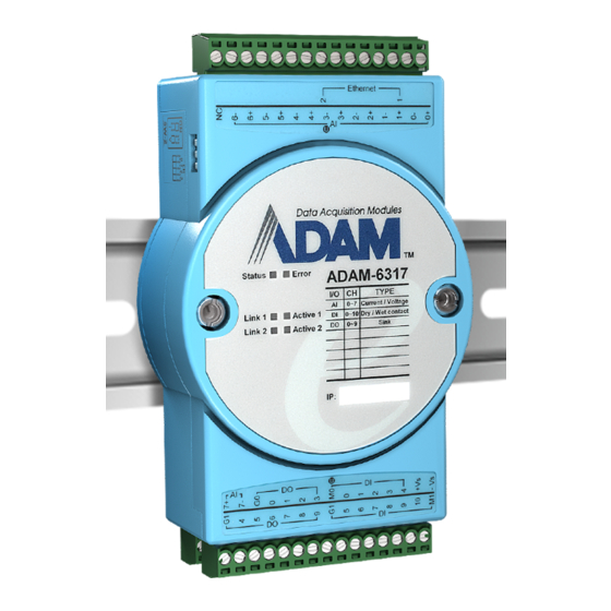
Analog Input Modules (ADAM-6317) The ADAM-6317 is a high-density I/O module with a built-in 10/100BASE-T interface for seamless Ethernet connectivity. The module has 8 analog input, 11 digital inputs and 10 digital outputs with 2,500 VDC isolation protection. 3.3.1 Specifications Analog Input Channels: 8 (differential) ... - Page 27 Figure 3.5 Digital Input Wiring Figure 3.6 Digital Output Wiring Figure 3.7 “U”(Upper) and Bottom Terminal Block ADAM-6300 User Manual...
-
Page 28: Ssr Relay Output Module Modules (Adam-6360D)
SSR Relay Output Module Modules (ADAM- 6360D) The ADAM-6360D is a high-density I/O module with a built-in 10/100BASE-T inter- face for seamless Ethernet connectivity. The module has 8 SSR(Solid-State Relay) relay output, 14 digital inputs and 6 digital outputs with 2,500 VDC isolation protec- tion. -
Page 29: Application Wiring
3.4.2 Application Wiring Figure 3.8 Relay Output Wiring Figure 3.9 Digital Input Wiring ADAM-6300 User Manual... - Page 30 Figure 3.10 Digital Output Wiring Figure 3.11 “U”(Upper) and Bottom Terminal Block ADAM-6300 User Manual...
-
Page 31: System Configuration
Chapter System Configuration... -
Page 32: System Requirements
Installing Adam/Apax .NET Utility Adam/Apax .NET Utility is an application provided by Advantech for the configuration and operation of ADAM modules. The installation file is available for free download at http://www.advantech.com (click on Download Area under Service & Support for the latest version). -
Page 33: Adam/Apax .Net Utility Overview
Adam/Apax .NET Utility Overview Adam/Apax .NET Utility is a graphical interface for configuring and operating ADAM modules. The following text instructions describe how to use the utility. To start Adam/Apax .NET Utility, double-click the shortcut on the desktop or click the icon in the start menu folder. -
Page 34: Menu Bar
Allow Calibration Select this to enable/disable module calibration. Help Menu Check Up-to-Date on Connect to the Advantech download website and checks for the the Web latest version of the utility. This shows information on the version of Adam/Apax .NET Utility About currently installed on your computer. -
Page 35: Toolbar
4.3.2 Toolbar The toolbar contains icons for the most commonly used menu items. Figure 4.2 Adam/Apax .NET Utility Toolbar From left to right icon are: Open favorite group Save favorite group Search Modules Add Devices to Group Terminal for Command Testing Group Configuration Monitor Data Stream/Event Print Screen... -
Page 36: Module Tree Display Area
4.3.3 Module Tree Display Area Figure 4.3 Adam/Apax .NET Utility Module Display Area The Module Tree Display Area is the left part of the main window. There are five major categories in the display area, some of which will be visible only when you have certain modules connected: All serial I/O modules (ADAM-4000, ADAM-4100, and ADAM-5000 Serial... -
Page 37: Configuration Of Adam-6300 Modules
Configuration of ADAM-6300 Modules Once an ADAM-6300 module has been connected to the host PC and you have searched for it, you will find it listed in the Module Tree Display Area under the Ether- net category. Select the Ethernet category on the Module Tree Display Area and click the Search Modules icon on the Toolbar. -
Page 38: The Information Tab
4.4.1 The Information Tab It indicates basic information of ADAM-6300 module. This tab shows the firmware version as well as the device name and device descrip- tion, both of which can be modified from here. Giving your modules a specific name and description can be useful for when several ADAM-6300 modules are connected to the same network. -
Page 39: The Administration Tab
4.4.4 The Firmware Tab Advantech will occasionally release new firmware versions to add or improve the functionality of ADAM-6300 modules. Visit http://www.advantech.com to check for the latest firmware downloads. User can download System or IO Firmware file(Bin). -
Page 40: Getting Start: The Connection Of Opc Ua Server And Client
Getting start: The Connection of OPC UA Server and Client You can refer below flowchart of getting start guide, the connection of OPC UA Server(ADAM-6300) and Client(Adam/Apax .NET Utility). Figure 4.4 Flowchart of getting start guide, the connection of OPC UA Server(ADAM-6300) and Client(Adam/Apax .NET Utility) 4.5.1 Network and I/O type setting... - Page 41 In the Module Tree Display Area, right-click on the Ethernet group and click Search Device. If you see the module under the Others group, you need to change the IP address of the ADAM-6300 module so that it is the same subnet as the host PC. Enter the correct IP address, subnet address, and default gateway on the Status Display Area and then click Apply Change.
- Page 42 When you click on one of the individual channel items, you can select I/O type mode and click Apply mode for this channel or click Apply to CH12~17 for channel 12~17. ADAM-6300 User Manual...
-
Page 43: Connection Of Opc Ua Server And Opc Ua Client
4.5.2 Connection of OPC UA Server and OPC UA Client 4.5.2.1 Enter port number (OPC UA Client) EndPoint URL(opc.tcp://10.0.0.5:4840) has been set in default setting of Adam/Apax .NET Utility. Enter 4840 in Port Number if you use other OPC UA client. 4.5.2.2 Select Security policy, security mode and authorization ADAM-6300 supports two security options of sessions(OPC UA client). - Page 44 The log window shows “BadSecureChannelClosed”, since OPC UA client and server need to have bidirectional authentication at first connection. Go to Certificate tab for bidirectional authentication. a. Trusting the OPC UA Sever's certificate (on the OPC UA Client): Adam/ Apax .NET Utility automatically trusts ADAM-6300 (sever) certificate. You can see Local in Certificates tab.
- Page 45 b. Trusting the OPC UA Client's certificate: Please click Trust Certificate in ADAM tab, and ADAM-6300 module will be restarted to make certification take effect. And then you can see Trusted in Status of ADAM Client Certif- icate List. Please click Trust Certificate to trust client’s certificate. ADAM-6300 User Manual...
- Page 46 This certificate of status was changed to Trusted. Note! ADAM-6300 supports 8 trusted certificates. User can click Delete Cer- tificates and restart ADAM-6300 to remove certificates you don’t needed. Go to OPC UA tab to connect this session of OPC UA server and client again.
- Page 47 Attributes: the information that presents value of a variable, the read and write permissions of the variable, a textual description of the variable for node. Data Access View: to monitor changes of node’s attributes Subscriptions and Monitored Items: User establishs subscription in OPC UA server to monitor the value of monitored items in a periodic time.
-
Page 48: I/O Configuration
I/O Configuration Please see the below table for I/O channel of ADAM-6300 series. Digital Input Digital Output Support DI, Support DO, Analog Model Relay Support DI counter and Support DO pulse output, Input (VDC) mode frequency mode pulse output mode... - Page 49 Select this AI_IntegrationTime and right click Monitor And you can see this node(AI_IntegrationTime) in Data Access View box. Or you can left click and drag this node(AI_IntegrationTime) in Data Access View box. Burnout You can enable burn out function, to select AI_BurnOutEnable and right click Write. It's only support for 4 - 20mA input range.
- Page 50 Select AI_BurnOutEnable and right click Write Select True or False to enable or disable this function. a. True: enable burn out function b. False: disable burn out function Select this AI_BurnOutEnable and right click Monitor. Burnout value: If you select up scale, you will see the value FFFF in Modbus address when ADAM-6300 User Manual...
- Page 51 open circuit happens. Otherwise, it will show 0000 as down scale. It's only sup- port for 4 - 20mA input range. Select AI_BurnOutValue and right click Write Enter below value to choose up scale or down scale. a. 0: down scale b.
- Page 52 Select AI_BurnOutValue and right click Monitor Note! You need to enter 1 in AI_BurnOutEnable to enable burn out fuction at first. And then you can select up scale or down scale. 4.6.1.2 Individual Channel Configuration Input range This node allows you to set a different range for each channel. Select AI_(Channel)_Range and right click Write ADAM-6300 User Manual...
- Page 53 Enter below value to choose different input ranges. Enter Value Input Range 4~20 mA ± 10 V ± 5 V ± 1 V ± 500 mV ± 150 mV ± 20 mA 0 ~ 10 V 0 ~ 5 V 0 ~ 1 V 0 ~ 500 mV 0 ~ 150 mV...
- Page 54 AI_(Channel)_ScaledValue: You can see the scaled value if you select this AI_(Channel)_ScaledValue and right click Monitor AI_(Channel)_ChannelStatus: You can see the scaled value if you select this AI_(Channel)_ChannelStatus and right click Monitor. ADAM-6300 User Manual...
- Page 55 You can see the Value of this AI_(Channel)_ChannelStatus in Data Access View. a. 0: good b. 4: under range(4-20mA only) c. 8: burn out(4-20mA only) ADAM-6300 User Manual...
-
Page 56: Digital Input
4.6.2 Digital input Please see the below table for I/O channel of ADAM-6300 series. Digital Input Digital Output Support DI, Support DO, Analog Model Relay Support DI counter and Support DO pulse output, Input (VDC) mode frequency mode pulse output... - Page 57 Invert signal a. Select DI_(channel)_EnableInvert and right click Write b. Select True or False to enable or disable this function. The default setting is false. c. Right click to select Monitor to monitor this function. ADAM-6300 User Manual...
- Page 58 Digital filter It contains minimum high signal width and minimum low signal width (1- 65535) for filtering the noise. a. Select DI_(channel)_EnableFilter and right click Write b. Select True or False to enable or disable this function. The default setting is false.
- Page 59 Write in selected DI_(channel)_FilterWidthHigh), to enter 0~65535(The unit is 0.1ms). d. After above setting, left click and drag each of nodes of DI_(channel)_En- ableFilter, DI_(channel)_FilterWidthLow and DI_(channel)_Filter- WidthHigh to Data Access View, and start to monitor these nodes. ADAM-6300 User Manual...
- Page 60 Counter mode: A counter counts the number of pulse numbers of a digital signal from the selected channel and then records. Select DI_(channel)_CounterStart, and right click Write, click True to start counter and click False to close counter. The default setting is True. Select DI_(channel)_CounterValue a.
- Page 61 Select DI_(channel)_CounterRemain The function of counter remain is to keep last counter value when power off. a. Right click Write b. Select True or False to enable or disable the function. You can add the nodes of EnableInvert, EnableFilter, FilterWidthLow, Fil- terWidthHigh functions in Counter mode if user need these functions.
- Page 62 Frequency mode: When Frequency is selected, the module will calculate the frequency of the dig- ital input signal for the selected channel. Select DI_(channel)_FrequencyValue and right click Monitor The current frequency value of the selected channel will be displayed in the Value of Attributes of this DI_(channel)_ FrequencyValue in Data Access View.
-
Page 63: Digital Output
4.6.3 Digital Output Please see the below table for I/O channel of ADAM-6300 series. Digital Input Digital Output Relay (VDC) Analog Model Support DI, Support DO, Input Support DI counter and Support DO pulse output, mode frequency mode pulse output... - Page 64 c. 2: Pulse output continue mode Select this DO_(channel)_Mode and right click Monitor And you can see this node(DO_12_Mode) in Data Access View. Or you can left click and drag this this node(DO_12_Mode) in Data Access View box. ADAM-6300 User Manual...
- Page 65 DO mode: Select DO_(channel)_DOValue and right click to select Write And select True to turn on the DO. The default setting is false, which means DO off. Right click to select Monitor to monitor this DO status. Pulse output mode: Pulse output is for a finite number of pulses.
- Page 66 Select DO_(channel)_Mode, and right click to select Write and enter 1. Select DO_(Channel)_ PulseWidthLow and DO_(Channel)_ PulseWidth- High You can define the pulse width in the low signal width(right click Write in selected DO_(Channel)_ PulseWidthLow), and high signal width(right click Write in selected DO_(Channel)_PulseWidthHigh), to enter 0~65535(The unit is 0.1ms).
- Page 67 Select DO_(Channel)_PulseOutputCount, and right click Write the counter number. (The range is 0~4294967295) ADAM-6300 User Manual...
- Page 68 Select DO_(Channel)_PulseStart, and right click Write the True to start DO pulse. After above setting, left click and drag each of nodes of DO_(chan- nel)_Mode, DO_(Channel)_ PulseWidthLow, DO_(Channel)_Pulse- WidthHigh, DO_(Channel)_PulseOutputCount, DO_(Channel)_PulseStart, DO_(Channel)_PulseRemainingCount to Data Access View, and start to monitor these nodes. You can see the remaining counter in DO_(Channel)_PulseRemaining- Count.
- Page 69 Pulse output continue mode Pulse output Continue (for a pulse train) is to generate a continuous pulse train or finite number of pulses. Please follow below steps to implement pulse out function. Select DO_(channel)_Mode, and right click to select Write and enter 2. Select DO_(Channel)_PulseWidthLow and DO_(Channel)_PulseWidth- High You can define the pulse width in the low signal width(right click Write in...
- Page 70 Select DO_(Channel)_PulseStart, and right click Write the True to start DO pulse. After above settings, left click and drag each of nodes of DO_(chan- nel)_Mode, DO_(Channel)_ PulseWidthLow, DO_(Channel)_Pulse- WidthHigh, DO_(Channel)_PulseStart to Data Access View, and start to monitor these nodes. ADAM-6300 User Manual...
-
Page 71: Ssr Relay Output
4.6.4 SSR Relay Output SSR Relay Output mode: Select SSR_(channel)_RelayValue and right click to select Write And select True to turn on the relay. The default setting is false, which means relay off. Right click to select Monitor to monitor this SSR relay status. ADAM-6300 User Manual... - Page 72 No part of this publication may be reproduced in any form or by any means, electronic, photocopying, recording or otherwise, without prior written permis- sion of the publisher. All brand and product names are trademarks or registered trademarks of their respective companies. © Advantech Co., Ltd. 2021...
Need help?
Do you have a question about the ADAM-6300 Series and is the answer not in the manual?
Questions and answers