Table of Contents
Advertisement
Advertisement
Table of Contents

Related Manuals for Advantech AMAX-5000 Series


Summary of Contents for Advantech AMAX-5000 Series
- Page 1 User Manual AMAX-5000 Series EtherCAT Slice I/O Modules...
- Page 2 No part of this manual may be reproduced, copied, translated or transmitted in any form or by any means without the prior written permission of Advantech Co., Ltd. Information provided in this manual is intended to be accurate and reliable. How- ever, Advantech Co., Ltd.
- Page 3 This product has passed the CE test for environmental specifications when shielded cables are used for external wiring. We recommend the use of shielded cables. This kind of cable is available from Advantech. Please contact your local supplier for ordering information.
- Page 4 The sound pressure level at the operator's position according to IEC 704-1:1982 is no more than 70 dB (A). DISCLAIMER: This set of instructions is given according to IEC 704-1. Advantech disclaims all responsibility for the accuracy of any statements contained herein.
-
Page 5: Table Of Contents
Contents Chapter Introduction..........1 Introduction to AMAX-5000 slice I/O module ..........2 Table 1.1: Table 1.1: AMAX-5000 series extension modules..2 Chapter Hardware Installation ......5 Install / Remove the module..............6 2.1.1 Attach on the DIN-rail..............6 Figure 2.1 AMAX-5000 installed in control cabinet...... 6 2.1.2... - Page 6 Figure 4.11AMAX-5017V Module..........39 4.3.1 AMAX-5017V Specification............40 4.3.2 LED Indicator ................40 Figure 4.12AMAX-5017V Module LED Indicator ......40 Table 4.19: AMAX-5017V Module LED Indicator ......41 4.3.3 Pin Definition................41 Figure 4.13AMAX-5017V Module Front View......41 AMAX-5000 Series User Manual...
- Page 7 Table 4.43: Configuration Data of the Module (0x8000 - 0x8FFF) .. Table 4.44: Range (DT0800EN16) Enums........58 Table 4.45: Slew clock rate (DT0801EN16) Enums ....58 Table 4.46: Configuration Data of the Module (0x8000 - 0x8FFF) .. Table 4.47: Safety Value (DT0802EN16) Enums......58 AMAX-5000 Series User Manual...
- Page 8 Table 5.12: Lower 8 Pin Connector..........77 5.4.4 Application Wiring ............... 78 Figure 5.20Wiring for AMAX-5056SO ........78 5.4.5 Object Description and Parameterization ........78 AMAX-5057 16-ch Sink-type Digital Output Module ....... 79 Figure 5.21AMAX-5057 Module ..........79 AMAX-5000 Series User Manual viii...
- Page 9 Figure 5.29AMAX-5057SO Module Side View ......86 Table 5.17: Upper 6 Pin Connector ..........87 Table 5.18: Lower 12 Pin Connector ........... 87 5.6.4 Application Wiring ............... 87 Figure 5.30Wiring for AMAX-5057SO......... 87 5.6.5 Object Description and Parameterization ........88 AMAX-5000 Series User Manual...
- Page 10 AMAX-5000 Series User Manual...
-
Page 11: Chapter 1 Introduction
Chapter Introduction... -
Page 12: Introduction To Amax-5000 Slice I/O Module
Introduction to AMAX-5000 slice I/O module This manual will only introduce the AMAX-5000 series slice I/O modules. To know more about AMAX-5580 controller and AMAX-5400 series extension modules, please download AMAX-5580 user manual from our website. Advantech provides different I/O modules for various applications. The following table outlines Advantech's supported I/O modules. - Page 13 - 2xRJ45 - Abnormal Voltage detection AMAX-5074 Extension/Coupler *This module contains power input function, no need another AMAX-5001 to be the first power supply module EtherCAT Bus Extension AMAX-5079 - Extend EtherCAT by RJ45 AMAX-5000 Series User Manual...
- Page 14 AMAX-5000 Series User Manual...
-
Page 15: Chapter 2 Hardware Installation
Chapter Hardware Installation... -
Page 16: Install / Remove The Module
Install / Remove the module AMAX-5000 series has easy-install design to help you install and maintain your mod- ules easily. 2.1.1 Attach on the DIN-rail Please follow below steps to secure AMAX-5000 modules on the DIN-rail: Unlock the latches at the bottom of AMAX-5000 module. -
Page 17: Remove From The Din-Rail
You can easily detach the module by release the latch at the bottom of the module. Then you can draw out the module without any difficulty. Figure 2.2 Release the latch to remove the module Figure 2.3 AMAX-5000 module design AMAX-5000 Series User Manual... -
Page 18: I/O Wiring
AMAX-5000 I/O module. Use the screw driver to press the left notch on the terminal. Insert the wire into the terminal. Note! Please use # 14 AWG ~ 28 AWG wire for terminal block. AMAX-5000 Series User Manual... -
Page 19: Chapter 3 Infrastructure
Chapter Infrastructure... -
Page 20: Amax-5001 Smart Power Input Module With 4-Ch Di
The status can be shown on the LED and on the process data. Besides power input function, AMAX-5001 also equips 4-ch wet contact DI for user to connect to the system event. Figure 3.1 AMAX-5001 Module AMAX-5000 Series User Manual... -
Page 21: Amax-5001 Application
LED Indicator: PWR, RUN, Power Diagnosis LED 3.1.2.2 Power Input Rated Voltage: 24V (±20%) Dual Power Input: Supported Max Current on Bus: 2A Diagnosis Function: – Over/under voltage for input 1&2 – Over current output on bus AMAX-5000 Series User Manual... -
Page 22: Led Indicator
Table 3.1: AMAX-5001 Module LED Indicator Color Indication Behavior Green Power on Green EtherCAT connection Green BUS power on BUS over current Vin1 over voltage (30V) Vin2 over voltage (30V) Vin1 under voltage (10.7V) Vin2 under voltage(10.7V) AMAX-5000 Series User Manual... -
Page 23: Pin Definition
3.1.4 Pin Definition Figure 3.4 AMAX-5001 Module Front View Figure 3.5 AMAX-5001 Module Side View AMAX-5000 Series User Manual... -
Page 24: Application Wiring
Table 3.2: Upper 4 Pin Connector Pin Number Pin Definition Table 3.3: Lower 8 Pin Connector Pin Number Pin Definition DI_COM DI_COM 3.1.5 Application Wiring Figure 3.6 Wiring for AMAX-5001 Digital Input AMAX-5000 Series User Manual... -
Page 25: Object Description And Parameterization
The digital input channel 3 UINT 0x00 6000:11 Voltage_1 The value of the Voltage 1 REAL 0x00 6000:12 Voltage_2 The value of the Voltage 2 REAL 0x00 6000:13 Current The value of the Current REAL 0x00 AMAX-5000 Series User Manual... -
Page 26: Amax-5074 Ethercat Coupler With Id Switch
Connector’: Pluggable 4P push-in terminal (#24~16 AWG) and 2x RJ45 Enclosure: PC Power Consumption: 2.5W @ 24V Protocol: EtherCAT Transmission Rate: 100Mbps Distributed Clock: Default not supported LED Indicator: PWR, RUN, Power Diagnosis LED AMAX-5000 Series User Manual... -
Page 27: Led Indicator
Bus Interface: 2 x RJ45 (1 x Input, 1 x Output) 3.2.1.4 Environment Operation Temperature: -10~60°C (vertical mounted) Storage Temperature: -40~85°C Relative Humidity: 5~95% (non-condense) 3.2.2 LED Indicator Figure 3.9 AMAX-5074 Module LED Indicator AMAX-5000 Series User Manual... -
Page 28: Id Switch
Vin2 under voltage(19.2V) 3.2.3 ID Switch Figure 3.10 AMAX-5074 ID Switch Table 3.6: AMAX-5074 ID Switch Switch Number Multiple Range (HEX) Example (SW2, SW1) = (4, C), then ID = 4 x16 + C x1 = 76 AMAX-5000 Series User Manual... -
Page 29: Pin Definition
3.2.4 Pin Definition Figure 3.11 AMAX-5074 Module Front View Figure 3.12 AMAX-5074 Module Side View AMAX-5000 Series User Manual... -
Page 30: Application Wiring
0x00 6000:06 Device_ID ID Switch UINT 0x00 6000:11 Voltage_1 The value of the Voltage 1 FLOAT 0x00 6000:12 Voltage_2 The value of the Voltage 2 FLOAT 0x00 6000:13 Current The value of the Current FLOAT 0x00 AMAX-5000 Series User Manual... -
Page 31: Amax-5079 Ethercat Extension
Figure 3.14 AMAX-5079 Module 3.3.1 AMAX-5079 Specification 3.3.1.1 General: Certification: CE, FCC class A Connector’: 1 x RJ45 Enclosure: PC Power Consumption: N/A Protocol: EtherCAT Transmission Rate: 100Mbps LED Indicator: N/A AMAX-5000 Series User Manual... -
Page 32: Pin Definition
Bus Interface: 1 x RJ45 Power from bus: N/A 3.3.1.3 Environment Operation Temperature: -10~60°C (vertical mounted) Storage Temperature: -40~85°C Relative Humidity: 5~95% (non-condense) 3.3.2 Pin Definition Figure 3.15 AMAX-5079 Module Front View AMAX-5000 Series User Manual... - Page 33 Figure 3.16 AMAX-5079 Module Side View Table 3.10: LAN Port LAN Number LAN Definition EtherCAT signal output AMAX-5000 Series User Manual...
- Page 34 AMAX-5000 Series User Manual...
-
Page 35: Chapter 4 Analog Input/Output Modules
Chapter Analog Input/Output Modules... -
Page 36: Amax-5015 4-Ch Rtd Input Module
Certification: CE, FCC class A Connector: Pluggable 4P+8P push-in terminal (#24~16 AWG) Enclosure: PC Power Consumption: 2W @ 24VDC Protocol: EtherCAT Transmission Rate: 100Mbps Distributed Clock: Default not supported LED Indicator: PWR, RUN AMAX-5000 Series User Manual... - Page 37 Resolution: 16 bit with ±0.1% FSR accuracy Sample Rate: 100 sample/s (per channel) Burn-out detection: Yes 4.1.1.3 Protection Isolation Voltage: 2000V 4.1.1.4 Environment Operation Temperature: -10~60°C (vertical mounted) Storage Temperature: -40~85°C Relative Humidity: 5~95% (non-condense) AMAX-5000 Series User Manual...
-
Page 38: Led Indicator
Figure 4.2 AMAX-5015 Module LED Indicator Table 4.1: AMAX-5015 Module LED Indicator Color Indication Behavior Green Power on Power Yellow Locating Module EtherCAT Connected Green Blink EtherCAT Connecting Run/Error EtherCAT Abnormal ON/Blink System Abnormal No Error AMAX-5000 Series User Manual... -
Page 39: Pin Definition
4.1.3 Pin Definition Figure 4.3 AMAX-5015 Module Front View Figure 4.4 AMAX-5015 Module Side View AMAX-5000 Series User Manual... -
Page 40: Application Wiring
Table 4.2: Upper 4 Pin Connector Pin Number Pin Definition RTD0+ RTD0- COM0 RTD1+ Table 4.3: Lower 8 Pin Connector Pin Number Pin Definition RTD1- COM1 RTD2+ RTD2- COM2 RTD3+ RTD3- COM3 4.1.4 Application Wiring Figure 4.5 Wiring for AMAX-5015 AMAX-5000 Series User Manual... -
Page 41: Object Description And Parameterization
Flags Default value Enable burn out 80n0:01 AIn_EnBurnOut BOOL for ch#n DT0800EN16 80n0:17 AIn_Range Type of ch#n (Pt100(385) - (16 bits) 50~150 'C) Enable burn out DT0802EN16 80n0:20 AIn_BurnOutValue 1 (up scale) for ch#n (16 bits) AMAX-5000 Series User Manual... - Page 42 The sampling rate of the DT0801E F600:17 AI_SamplingRate 0 (10Hz) module (total channel) 4.1.5.5 Enums (0x0800 - 0xFFF) Table 4.9: Burn Out Value (DT0802EN16) Enums Index (hex) Name Item Name Default value 10Hz DT0802EN16 0x0801 (Burn Out Value) 400Hz AMAX-5000 Series User Manual...
-
Page 43: Amax-5017C 6-Ch Current Input Module
The module provides 2000V optical isolation between channels. If any high voltage or current damage the channels, the whole system (other modules and control unit) won't be affected cause it is already isolated. Figure 4.6 AMAX-5017C Module AMAX-5000 Series User Manual... -
Page 44: Amax-5017C Specification
Environment Operation Temperature: -10~60°C (vertical mounted) Storage Temperature: -40~85°C Operating Humidity: 20 ~ 95% RH (non-condense) Storage Humidity: 0 ~ 95% RH (non-condense) 4.2.2 LED Indicator Figure 4.7 AMAX-5017C Module LED Indicator AMAX-5000 Series User Manual... -
Page 45: Pin Definition
Table 4.10: AMAX-5017C Module LED Indicator Color Indication Behavior Green Power on Power Yellow Locating Module EtherCAT Connected Green Blink EtherCAT Connecting Run/Error EtherCAT Abnormal ON/Blink System Abnormal No Error 4.2.3 Pin Definition Figure 4.8 AMAX-5017C Module Front View AMAX-5000 Series User Manual... - Page 46 Figure 4.9 AMAX-5017C Module Side View Table 4.11: Upper 4 Pin Connector Pin Number Pin Definition Table 4.12: Lower 8 Pin Connector Pin Number Pin Definition AMAX-5000 Series User Manual...
-
Page 47: Application Wiring
Data type Flags Default value Enable burn out 80n0:01 AIn_EnBurnOut BOOL for ch#n DT0800EN16 0x180 (4~20 80n0:17 AIn_Range Type of ch#n (16 bits) Enable burn out DT0802EN16 80n0:20 AIn_BurnOutValue 1 (up scale) for ch#n (16 bits) AMAX-5000 Series User Manual... - Page 48 Table 4.18: Configuration of the Module (0xF600 - 0xFFFF) Index (hex) Name Meaning Data type Flags Default value F600:01 LocateModule Turn on/off Locate LED BOOL The sampling rate of the DT0801E F600:17 AI_SamplingRate 0 (10Hz) module (total channel) AMAX-5000 Series User Manual...
-
Page 49: Amax-5017V 6-Ch Voltage Input Module
The module provides 2000 V optical isolation between channels. If any high voltage or current damage the channels, the whole system (other modules and control unit) won't be affected cause it is already isolated. Figure 4.11 AMAX-5017V Module AMAX-5000 Series User Manual... -
Page 50: Amax-5017V Specification
Environment Operation Temperature: -10~70°C (vertical mounted) Storage Temperature: -40~85°C Operating Humidity: 20 ~ 95% RH (non-condensing) Storage Humidity: 0 ~ 95% RH (non-condensing) 4.3.2 LED Indicator Figure 4.12 AMAX-5017V Module LED Indicator AMAX-5000 Series User Manual... -
Page 51: Pin Definition
Table 4.19: AMAX-5017V Module LED Indicator Color Indication Behavior Green Power on Power Yellow Locating Module EtherCAT Connected Green Blink EtherCAT Connecting Run/Error EtherCAT Abnormal ON/Blink System Abnormal No Error 4.3.3 Pin Definition Figure 4.13 AMAX-5017V Module Front View AMAX-5000 Series User Manual... - Page 52 Figure 4.14 AMAX-5017V Module Side View Table 4.20: Upper 4 Pin Connector Pin Number Pin Definition Table 4.21: Lower 8 Pin Connector Pin Number Pin Definition AMAX-5000 Series User Manual...
- Page 53 Configuration Data of the Module (0x8000 - 0x8FFF) Table 4.23: Configuration Data of the Module (0x8000 - 0x8FFF) Index (hex) Name Meaning Data type Flags Default value 80n0:17 AIn_Range Type of ch#n DT0800EN16 (16 bits) RW 0x143 (-10~10V) AMAX-5000 Series User Manual...
- Page 54 The sampling rate of the DT0801E F600:17 AI_SamplingRate 0 (10Hz) module (total channel) 4.3.5.5 Enums (0x0800 - 0xFFF) Table 4.26: Sampling Rate (DT0801EN16) Enums Index (hex) Name Item Name Default value 10Hz 0x0801 DT0801EN16 (Sampling Rate) 600Hz AMAX-5000 Series User Manual...
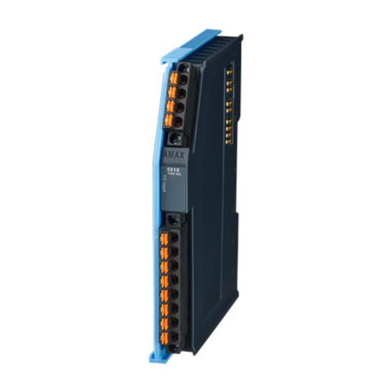
- Page 55 ±500 mV, ±1 V, ±2.5 V), each channel supports open load detection. The module pro- vides 2000 VDC optical isolation, if any surge voltage or current input the channel, the whole system (other modules or control unit) will not be damaged. Figure 4.16 AMAX-5018 Module AMAX-5000 Series User Manual...
- Page 56 4.4.1.3 Protection Isolation Voltage: 2000 V 4.4.1.4 Environment Operation Temperature: -25~60°C (vertical mounted) Storage Temperature: -40~85°C Operating Humidity: 20 ~ 95% RH (non-condensing) Storage Humidity: 0 ~ 95% RH (non-condensing) AMAX-5000 Series User Manual...
- Page 57 Figure 4.17 AMAX-5018 Module LED Indicator Table 4.27: AMAX-5018 Module LED Indicator Color Indication Behavior Green Power on Power Yellow Locating Module EtherCAT Connected Green Blink EtherCAT Connecting Run/Error EtherCAT Abnormal ON/Blink System Abnormal No Error AMAX-5000 Series User Manual...
- Page 58 4.4.3 Pin Definition Figure 4.18 AMAX-5018 Module Front View Figure 4.19 AMAX-5018 Module Side View AMAX-5000 Series User Manual...
- Page 59 Table 4.28: Upper 4 Pin Connector Pin Number Pin Definition Table 4.29: Lower 8 Pin Connector Pin Number Pin Definition 4.4.4 Application Wiring Figure 4.20 Wiring for AMAX-5018 AMAX-5000 Series User Manual...
- Page 60 When burn out enabled, conversion time per channel = 7.8ms. (21.4Hz per channel) Under and over range If thermocouple input < Range_Min without wire burnout, AI# shows Range_Min If thermocouple input > Range_Max without wire burnout, AI# shows Range_Max (Supported only when the channel's range type is thermocouple.) AMAX-5000 Series User Manual...
- Page 61 0x102 +/-500 mV 0x104 +/-1 V 0x140 +/-2.5 V 0x141 DT0800EN16 K 0~1370°C 0x420 0x0800 +/-50 mV J 0~760°C 0x400 (Range) E 0~1000°C 0x460 T -100~400°C 0x440 R 500~1750°C 0x480 S 500~1750°C 0x4A0 B 500~1800°C 0x4C0 AMAX-5000 Series User Manual...
- Page 62 The CJC offset of the F600:19 CJC_Offset module CJC offset = DINT CJC_Offset/10 4.4.5.7 Enums (0x0800 - 0xFFF) Table 4.37: Sampling Rate (DT0801EN16) Enums Index (hex) Name Item Name Default value 10Hz 0x0801 DT0801EN16 (Sampling Rate) 600Hz AMAX-5000 Series User Manual...
- Page 63 The module provides 2000 VDC optical isolation, if any high voltage or current damage the channels, the whole system (other modules or control unit) will not be damaged. Figure 4.21 AMAX-5024 Module AMAX-5000 Series User Manual...
- Page 64 Environment Operation Temperature: -20~60°C (vertical mounted) Storage Temperature: -40~85°C Operating Humidity: 20 ~ 95% RH (non-condensing) Storage Humidity: 0 ~ 95% RH (non-condensing) 4.5.2 LED Indicator Figure 4.22 AMAX-5024 Module LED Indicator AMAX-5000 Series User Manual...
- Page 65 Table 4.38: AMAX-5024 Module LED Indicator Color Indication Behavior Green Power on Power Yellow Locating Module EtherCAT Connected Green Blink EtherCAT Connecting Run/Error EtherCAT Abnormal ON/Blink System Abnormal No Error 4.5.3 Pin Definition Figure 4.23 AMAX-5024 Module Front View AMAX-5000 Series User Manual...
- Page 66 Figure 4.24 AMAX-5024 Module Side View Table 4.39: Upper 4 Pin Connector Pin Number Pin Definition Table 4.40: Lower 8 Pin Connector Pin Number Pin Definition AO0+ Iso. GND AO1+ Iso. GND AO2+ Iso. GND AO3+ Iso. GND AMAX-5000 Series User Manual...
- Page 67 Index (hex) Name Meaning Data type Flags Default value AOn_EnSlewR Enable slew rate 80n0:02 BOOL function DT0800EN16 0x180 (4~20 80n0:17 AOn_Range Type of ch#n (16 bits) 80n0:21 AOn_SlewRate Slew rate setting DT801EN16 0x00 (n=0~3 for Ch0~3) AMAX-5000 Series User Manual...
- Page 68 LocateModule BOOL F600:18 AO_SafetyValue Set AO safety value DT802EN16 0 (zero) 4.5.5.7 Enums (0x0800 - 0xFFF) Table 4.47: Safety Value (DT0802EN16) Enums Index (hex) Name Item Name Default value Zero 0x0802 DT0802EN16 (Safety Value) Last Value AMAX-5000 Series User Manual...
-
Page 69: Chapter 5 Digital Module
Chapter Digital Module... -
Page 70: Amax-5051 8-Ch Digital Input Module
Connector: Pluggable 4P+8P push-in terminal (#24~16 AWG) Enclosure: PC Power Consumption: 2W @ 24V Protocol: EtherCAT Transmission Rate: 100Mbps Distributed Clock: Default not supported LED Indicator: PWR, RUN, DI status AMAX-5000 Series User Manual... -
Page 71: Led Indicator
Figure 5.2 AMAX-5051 Module LED Indicator Table 5.1: AMAX-5051 Module LED Indicator Color Indication Behavior Power Green Power on Green EtherCAT connection Green Blink When TX/RX data in transmission Dry/Wet Logic "1" DI0~7 Green Dry/Wet Logic "0" AMAX-5000 Series User Manual... -
Page 72: Pin Definition
5.1.3 Pin Definition Figure 5.3 AMAX-5051 Module Front View Figure 5.4 AMAX-5051 Module Side View AMAX-5000 Series User Manual... -
Page 73: Application Wiring
Table 5.2: Upper 4 Pin Connector Pin Number Pin Definition DI_COM DI_COM Iso. GND Iso. GND Table 5.3: Lower 8 Pin Connector Pin Number Pin Definition 5.1.4 Application Wiring Figure 5.5 Wiring for AMAX-5051 AMAX-5000 Series User Manual... -
Page 74: Object Description And Parameterization
0x00 3001:04 Digital Input Channel 3 BOOLEAN 0x00 3001:05 Digital Input Channel 4 BOOLEAN 0x00 3001:06 Digital Input Channel 5 BOOLEAN 0x00 3001:07 Digital Input Channel 6 BOOLEAN 0x00 3001:08 Digital Input Channel 7 BOOLEAN 0x00 AMAX-5000 Series User Manual... -
Page 75: Amax-5052 16-Ch Digital Input Module
Certification: CE, FCC class A Connector: Pluggable 6P+12P push-in terminal (#28~16 AWG) Enclosure: PC Power Consumption: 2W @ 24V Protocol: EtherCAT Transmission Rate: 100Mbps Distributed Clock: Default not supported LED Indicator: PWR, RUN AMAX-5000 Series User Manual... -
Page 76: Led Indicator
Table 5.4: AMAX-5052Module LED Indicator Color Indication Behavior Power Green Power on Green EtherCAT connection Green Blink When TX/RX data in transmission Dry/Wet Logic "1" DI0~7 Green Dry/Wet Logic "0" Dry/Wet Logic "1" DI8~15 Yellow Dry/Wet Logic "0" AMAX-5000 Series User Manual... -
Page 77: Pin Definition
5.2.3 Pin Definition Figure 5.8 AMAX-5052 Module Front View Figure 5.9 AMAX-5052 Module Side View AMAX-5000 Series User Manual... -
Page 78: Application Wiring
Table 5.5: Upper 6Pin Connector Pin Number Pin Definition DI_COM Iso. GND Table 5.6: Lower 8 Pin Connector Pin Number Pin Definition DI10 DI11 DI12 DI13 DI14 DI15 5.2.4 Application Wiring Figure 5.10 Wiring for AMAX-5052 AMAX-5000 Series User Manual... -
Page 79: Object Description And Parameterization
Digital Input Channel 11 BOOLEAN 0x00 3002:05 DI12 Digital Input Channel 12 BOOLEAN 0x00 3002:06 DI13 Digital Input Channel 13 BOOLEAN 0x00 3002:07 DI14 Digital Input Channel 14 BOOLEAN 0x00 3002:08 DI15 Digital Input Channel 15 BOOLEAN 0x00 AMAX-5000 Series User Manual... -
Page 80: Amax-5056 8-Ch Sink-Type Digital Output Module
Connector: Pluggable 4P+8P push-in terminal (#24~16 AWG) Enclosure: PC Power Consumption: 2W @ 24V Protocol: EtherCAT Transmission Rate: 100Mbps Distributed Clock: Default not supported LED Indicator: PWR, RUN, DO status AMAX-5000 Series User Manual... -
Page 81: Led Indicator
Figure 5.12 AMAX-5056 Module LED Indicator Table 5.7: AMAX-5056 Module LED Indicator Color Indication Behavior Power Green Power on Green EtherCAT connection Green Blink When TX/RX data in transmission DO turn on DI0~7 Green DO turn off AMAX-5000 Series User Manual... -
Page 82: Pin Definition
5.3.3 Pin Definition Figure 5.13 AMAX-5056 Module Front View Figure 5.14 AMAX-5056 Module Side View AMAX-5000 Series User Manual... -
Page 83: Application Wiring
Table 5.8: Upper 4 Pin Connector Pin Number Pin Definition PCOM PCOM Iso. GND Iso. GND Table 5.9: Lower 8 Pin Connector Pin Number Pin Definition 5.3.4 Application Wiring Figure 5.15 Wiring for AMAX-5056 AMAX-5000 Series User Manual... -
Page 84: Object Description And Parameterization
LED to indicate digital status. The module provides 2,000 optical isolation between channels. If any high voltage or current damage the channels, the whole system (other modules, and control unit) won't be affected because it is already isolated. Figure 5.16 AMAX-5056SO Module AMAX-5000 Series User Manual... -
Page 85: Amax-5056So Specification
Isolation Voltage: 2,000V Internal Flyback diode for inductive load 5.4.1.4 Environment Operation Temperature: -10~60°C (vertical mounted) Storage Temperature: -40~85°C Relative Humidity: 5~95% (non-condense) 5.4.2 LED Indicator Figure 5.17 AMAX-5056SO Module LED Indicator AMAX-5000 Series User Manual... -
Page 86: Pin Definition
Table 5.10: AMAX-5056SO Module LED Indicator Color Indication Behavior Power Green Power on Green EtherCAT connection Green Blink When TX/RX data in transmission DO turn on DI0~7 Green DO turn off 5.4.3 Pin Definition Figure 5.18 AMAX-5056SO Module Front View AMAX-5000 Series User Manual... - Page 87 Figure 5.19 AMAX-5056SO Module Side View Table 5.11: Upper 4 Pin Connector Pin Number Pin Definition Iso. GND Iso. GND Table 5.12: Lower 8 Pin Connector Pin Number Pin Definition AMAX-5000 Series User Manual...
-
Page 88: Application Wiring
0x00 3101:04 Digital Output Channel 3 BOOLEAN 0x00 3101:05 Digital Output Channel 4 BOOLEAN 0x00 3101:06 Digital Output Channel 5 BOOLEAN 0x00 3101:07 Digital Output Channel 6 BOOLEAN 0x00 3101:08 Digital Output Channel 7 BOOLEAN 0x00 AMAX-5000 Series User Manual... -
Page 89: Amax-5057 16-Ch Sink-Type Digital Output Module
Connector: Pluggable 6P+12P push-in terminal (#28~16 AWG) Enclosure: PC Power Consumption: 2.5W @ 24V Protocol: EtherCAT Transmission Rate: 100Mbps Distributed Clock: Default not supported LED Indicator: PWR, RUN AMAX-5000 Series User Manual... -
Page 90: Led Indicator
Table 5.13: AMAX-5057 Module LED Indicator Color Indication Behavior Power Green Power on Green EtherCAT connection Green Blink When TX/RX data in transmission DO turn on DI0~7 Green DO turn off DO turn on DI8~15 Yellow DO turn off AMAX-5000 Series User Manual... -
Page 91: Pin Definition
5.5.3 Pin Definition Figure 5.23 AMAX-5057 Module Front View Figure 5.24 AMAX-5057 Module Side View AMAX-5000 Series User Manual... -
Page 92: Application Wiring
Table 5.14: Upper 6 Pin Connector Pin Number Pin Definition PCOM Iso. GND Table 5.15: Lower 12 Pin Connector Pin Number Pin Definition DO10 DO11 DO12 DO13 DO14 DO15 5.5.4 Application Wiring Figure 5.25 Wiring for AMAX-5057 AMAX-5000 Series User Manual... -
Page 93: Object Description And Parameterization
Digital Output Channel 11 BOOLEAN 0x00 3102:05 DO12 Digital Output Channel 12 BOOLEAN 0x00 3102:06 DO13 Digital Output Channel 13 BOOLEAN 0x00 3102:07 DO14 Digital Output Channel 14 BOOLEAN 0x00 3102:08 DO15 Digital Output Channel 15 BOOLEAN 0x00 AMAX-5000 Series User Manual... -
Page 94: Amax-5057So 16-Ch Source-Type Digital Output Module
Connector: Pluggable 6P+12P push-in terminal (#28~16 AWG) Enclosure: PC Power Consumption: 2.5W @ 24V Protocol: EtherCAT Transmission Rate: 100Mbps Distributed Clock: Default not supported LED Indicator: PWR, RUN AMAX-5000 Series User Manual... -
Page 95: Led Indicator
Table 5.16: AMAX-5057SO Module LED Indicator Color Indication Behavior Power Green Power on Green EtherCAT connection Green Blink When TX/RX data in transmission DO turn on DI0~7 Green DO turn off DO turn on DI8~15 Yellow DO turn off AMAX-5000 Series User Manual... -
Page 96: Pin Definition And Wiring
5.6.3 Pin Definition and Wiring Figure 5.28 AMAX-5057SO Module Front View Figure 5.29 AMAX-5057SO Module Side View AMAX-5000 Series User Manual... -
Page 97: Application Wiring
Table 5.17: Upper 6 Pin Connector Pin Number Pin Definition Iso. GND Table 5.18: Lower 12 Pin Connector Pin Number Pin Definition DO10 DO11 DO12 DO13 DO14 DO15 5.6.4 Application Wiring Figure 5.30 Wiring for AMAX-5057SO AMAX-5000 Series User Manual... -
Page 98: Object Description And Parameterization
Digital Output Channel 11 BOOLEAN 0x00 3102:05 DO12 Digital Output Channel 12 BOOLEAN 0x00 3102:06 DO13 Digital Output Channel 13 BOOLEAN 0x00 3102:07 DO14 Digital Output Channel 14 BOOLEAN 0x00 3102:08 DO15 Digital Output Channel 15 BOOLEAN 0x00 AMAX-5000 Series User Manual... - Page 99 AMAX-5000 Series User Manual...
- Page 100 No part of this publication may be reproduced in any form or by any means, such as electronically, by photocopying, recording, or otherwise, without prior written permission from the publisher. All brand and product names are trademarks or registered trademarks of their respective companies. © Advantech Co., Ltd. 2020...
Need help?
Do you have a question about the AMAX-5000 Series and is the answer not in the manual?
Questions and answers