Table of Contents
Advertisement
Advertisement
Table of Contents

Related Manuals for Advantech ADAM-5013


Summary of Contents for Advantech ADAM-5013
- Page 1 User Manual ADAM-5000 Series I/O Modules...
- Page 2 No part of this manual may be reproduced, copied, translated or transmitted in any form or by any means without the prior written permission of Advantech Co., Ltd. Information provided in this manual is intended to be accurate and reliable. How- ever, Advantech Co., Ltd.
- Page 3 This product has passed the CE test for environmental specifications when shielded cables are used for external wiring. We recommend the use of shielded cables. This kind of cable is available from Advantech. Please contact your local supplier for ordering information.
- Page 4 The sound pressure level at the operator's position according to IEC 704-1:1982 is no more than 70 dB (A). DISCLAIMER: This set of instructions is given according to IEC 704-1. Advantech disclaims all responsibility for the accuracy of any statements contained herein.
-
Page 5: Table Of Contents
Analog Input Modules ................3 1.2.1 ADAM-5013 3-ch RTD Input Module ..........3 Figure 1.1 ADAM-5013 Module Front View ......... 3 Figure 1.2 RTD Inputs ..............4 Table 1.2: Technical Specifications of ADAM-5013 ....4 Figure 1.3 Applying Calibration Resistance......... 5 Table 1.3: Calibration Resistances of ADAM-5013 ..... - Page 6 Chapter Analog I/O Module Calibration..23 Analog I/O Module Calibration ............... 24 3.1.1 ADAM-5000 Series Analog Input Module Calibration....24 Figure 3.1 Applying Calibration Voltage ........24 Table 3.1: Calibration Voltage of ADAM-5017/5018 ....27 Table 3.2: Calibration Voltage (ADAM-5017H) ......27 Table 3.3: Calibration Voltage of ADAM-5018P ......
- Page 7 Chapter Relay Output Modules.......47 Relay Output Modules................48 5.1.1 ADAM-5060 Relay Output Module..........48 Figure 5.1 ADAM-5060 Module Frontal View ......48 Figure 5.2 Relay Output............. 48 Table 5.1: Technical Specifications of ADAM-5060 ....48 5.1.2 ADAM-5069 Relay Output Module..........49 Figure 5.3 ADAM-5069 Module Front View Wiring....
- Page 8 Table 7.7: Jumper Setting ............76 Table 7.8: Switch setting ............76 Table 7.9: ADAM-5091 Technical Specifications ...... 77 7.1.3 ADAM-5095 2-port CAN Serial Communication Module with isolation protection (Only for ADAM-5560 Series) ...... 78 Figure 7.8 ADAM-5095 Module ..........78 Table 7.10: CAN Serial Port Pin Assignment (CAN1 ~ CAN2) ...
-
Page 9: Chapter 1 Overview
Chapter Overview... -
Page 10: Introduction
ADAM-5000 series of I/O modules. To organize an ADAM-5510 Series Controller, you need to select I/O modules to interface the main unit with field devices or processes that you have previously determined. Advantech provides the following types of ADAM-5000 I/O modules for various applications so far. Following table is the I/O modules support list we provided for user’s choice. -
Page 11: Analog Input Modules
1.2.1 ADAM-5013 3-ch RTD Input Module The ADAM-5013 is a 16-bit, 3-channel RTD input module that features programmable input ranges on all channels. This module is an extremely cost-effective solution for industrial mea- surement and monitoring applications. Its opto-isolated inputs provide 3,000 V... -
Page 12: Figure 1.2 Rtd Inputs
Application Wiring Figure 1.2 RTD Inputs Technical Specifications of ADAM-5013 Table 1.2: Technical Specifications of ADAM-5013 Analog input channels Input type Pt or Ni RTD type and temperature range Pt -100 to 100°C a=0.00385 Pt 0 to 100°C a=0.00385 Pt 0 to 200°C a=0.00385 Pt 0 to 600°C a=0.00385... -
Page 13: Figure 1.3 Applying Calibration Resistance
Connect the correct reference self resistance between the screw terminals of the ADAM-5013 as shown in the following wiring diagram. Table 2 below shows the correct values of the span and zero calibration resistances to be connected. Ref- erence resistances used can be from a precision resistance decade box or from discrete resistors with the values 60, 140, 200 and 440 ohms. -
Page 14: Adam-5017 8-Ch Analog Input Module
1.2.2 ADAM-5017 8-ch Analog Input Module The ADAM-5017 is a 16-bit, 8-channel analog differential input module that provides program- mable input ranges on all channels. It accepts millivolt inputs (±150mV , ±500mV), voltage inputs (±1V , ±5V and ±10V) and current input (±20 mA). The module provides data to the host computer in engineering units (mV , V or mA). -
Page 15: Figure 1.6 Process Current Input
Figure 1.6 Process Current Input Note! To keep measurement accuracy please short the channels that are not in use. Figure 1.7 Locations of Jumpers Technical Specifications of ADAM-5017 Table 1.4: Technical Specifications of ADAM-5017 Analog Input Channels Eight differential Input Type mV, V, mA Input Range ±... -
Page 16: Adam-5017P 8-Ch Ai With Independent Input
1.2.3 ADAM-5017P 8-ch AI with independent Input The ADAM-5017P is a 16-bit, 8-channel analog differential input and independent configuration module. It accepts millivolt inputs (±150mV, ±500mV, 0~150mV, 0~500mV, 0~1V, 0~5V, 0~10V, 0~15V), voltage inputs (±1V, ±5V, ±10V, and ±20V) and current input (±20 mA, 4~20mA). The module provides data to the host computer in engineering units (mV, V (supports uni-poloar and bipolar) or mA). -
Page 17: Figure 1.11Locations Of Jumpers
Note! To keep measurement accuracy please short the channels that are not in use. Figure 1.11 Locations of Jumpers Table 1.5: Technical Specifications of ADAM-5017P Analog Input Channels Eight differential and independent Input Type mV, V (uni-polar and bipolar), mA Input Range ±... -
Page 18: Adam-5017H 8-Ch High Speed Analog Input Module
1.2.4 ADAM-5017H 8-ch High Speed Analog Input Module ADAM-5017H is an 8-ch analog differential input module that provides programmable input ranges on each channel. The module provides data to the host microprocessor in engineering units (mV, V or mA) or two’s complement format. Its sampling rate depends on the data format received: up to 100 Hz (total). -
Page 19: Figure 1.15Locations Of Jumpers
Figure 1.15 Locations of Jumpers Note! To maintain measurement accuracy pleases short channels not in use. Table 1.6: Technical Specifications of ADAM-5017H Analog Input Channels 8 differential ADC Resolution 12 bits, plus sign bit Type of ADC Successive approximation Isolation Voltage 3000 V Sampling Rate 100 Hz... -
Page 20: Table 1.7: Adam-5017H Input Signal Ranges
Table 1.7: ADAM-5017H Input Signal Ranges Input With Offset Offset Gain Gain Error Offset Drift Gain Display Range Over- Error @ Error @ Error @ -10 to Drift Resolution ranging 25°C -10 to @ 25°C +70°C +70°C Voltage 0 ~ 10 V 0 ~ 11 V ±1 LSB ±2 LSB ±1 LSB ±2 LSB 17 µV/°C... -
Page 21: Adam-5017Uh 8-Ch Ultra High Speed Analog Input Module
1.2.5 ADAM-5017UH 8-ch Ultra High Speed Analog Input Module The ADAM-5017UH is a 12-bit plus sign bit, 8-channel analog differential input module that pro- vides programmable input ranges on each channel. It accepts voltage inputs (±10 V and 0-10 V) and current inputs (0-20 mA and 4-20 mA). -
Page 22: Figure 1.19Locations Of Rc Filter Jumper Setting
Figure 1.19 Locations of RC Filter Jumper Setting Figure 1.20 Locations of RC Filter Jumper Setting Note! To maintain measurement accuracy please short channels not in use. ADAM-5000 Series User Manual... -
Page 23: Table 1.8: Technical Specifications Of Adam-5017Uh
Table 1.8: Technical Specifications of ADAM-5017UH Analog Input Channels Eight differential Resolution 12 bits Input Type mV, V, mA Input Range +0~10V , ± 10 V , +4~20mA and ± 20 mA Isolation Voltage 3000 VDC Sampling Rate 200k samples/sec (single channel) 50k samples/sec (8 channel) Analog Input Signal Limit 15 V max. -
Page 24: Adam-5018 7-Ch Thermocouple Input Module
1.2.6 ADAM-5018 7-ch Thermocouple Input Module The ADAM-5018 is a 16-bit, 7-channel thermocouple input module that features pro- grammable input ranges on all channels. It accepts millivolt inputs (±15 mV , ±50 mV , ±100 mV , ±500 mV), voltage inputs (±1 V , ±2.5 V), current input (±20 mA, requires 125 ohms resistor) and thermocouple input (J, K, T , R, S, E, B). -
Page 25: Table 1.10: Technical Specifications Of Adam-5018
Table 1.10: Technical Specifications of ADAM-5018 Analog Input Channels Seven differential Input Type mV, V, mA, Thermocouple Input Range ± 15 mV, ± 50 mV, ± 100 mV, ± 500 mV, ± 1 V, ± 2.5 V and ± 20 mA T/C Type and 0 to 760 °C Temperature Range... -
Page 26: Figure 1.24Thermocouple Input
Application Wiring Figure 1.24 Thermocouple Input Table 1.11: Technical Specifications of ADAM-5018P Analog Input Channels Seven differential & independent thermocouple Input Type mV, V, mA, Thermocouple Input Range ± 15 mV, ± 50 mV, ± 100 mV, ± 500 mV, ± 1 V, ± 2.5 V and ±... - Page 27 Chapter Analog Output Modules...
-
Page 28: Chapter 2 Analog Output Modules
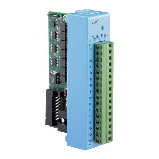
Analog Output Modules 2.1.1 ADAM-5024 4-ch Analog Output Module The ADAM-5024 is a 4-channel analog output module. It receives its digital input through the RS-485 interface of the ADAM-5510 system module from the host computer. The format of the data is engineering units. It then uses the D/A converter controlled by the system module to convert the digital data into output signals. -
Page 29: Table 2.1: Technical Specifications Of Adam-5024
Technical Specifications of ADAM-5024 Table 2.1: Technical Specifications of ADAM-5024 Analog Output Channels Four Output Type V, mA Output Range 0-20mA, 4-20mA, 0-10V Isolation Voltage 3000 Vdc Output Impedance 0.5 Ohms Accuracy ±0.1% of FSR for current output ±0.2% of FSR for voltage output Zero Drift Voltage output: ±30 µV/ºC Current output: ±0.2 µA/ºC... - Page 30 ADAM-5000 Series User Manual...
- Page 31 Chapter Analog I/O Module Calibration...
-
Page 32: Adam-5000 Series Analog Input Module Calibration
Analog I/O Module Calibration Analog input/output modules are calibrated when you receive them. However, cali- bration is sometimes required. No screwdriver is necessary because calibration is done in software with calibration parameters stored in the ADAM-5000 analog I/O module‘s onboard EEPROM. The ADAM-5000 system comes with the ADAM utility software that supports calibration of analog input and analog output. - Page 33 ”Enable Calibration Function” in “Setup” menu. Use a precision voltage source to apply a span calibration voltage to the mod- ule's V0+ and V0- terminals. Click "Zero" and apply the voltage as pop out windows to the Ch-0 and click "Apply."...
- Page 34 Click “Span” and apply the voltage as pop out windows to the Ch-0 and click “Apply.” Note! Zero calibration and span calibration must be completed before CJC calibration. To calibrate CJC, the thermocouple attached to ADAM-5018 and a standard thermometer should be used to measure a standard known temperature, such as the freezing point of pure water.
-
Page 35: Table 3.1: Calibration Voltage Of Adam-5017/5018
Table 3.1: Calibration Voltage of ADAM-5017/5018 Module Input Range Input Range Span Calibration Code (Hex) Voltage 5018 ±15 mV +15 mV ±50 mV +50 mV ±100 mV +100 mV ±500 mV +500 mV ±1 mV +1 V ±2.5 V +2.5 V ±20 mV +20 mA (1) J thermocouple 0 to 1370°C... -
Page 36: Table 3.3: Calibration Voltage Of Adam-5018P
Table 3.3: Calibration Voltage of ADAM-5018P Module Input Range Code Input Range Span Calibration (Hex) Voltage 5018P ±15 mV +15 mV ±50 mV +50 mV ±100 mV +100 mV ±500 mV +500 mV ±1 mV +1 V ±2.5 V +2.5 V ±20 mV +20 mA (1) 4 ~ 20 mA... -
Page 37: Analog Output Module Calibration
3.1.2 Analog Output Module Calibration The output current of analog output modules can be calibrated by using a low calibra- tion value and a high calibration value. The analog output modules can be configured for one of two ranges: 0-20 mA and 4-20 mA. Since the low limit of the 0-20 mA range (0 mA) is internally an absolute reference (no power or immeasurably small power), just two levels are needed for calibration: 4 mA and 20 mA. - Page 38 Issue the 4 mA Calibration command to indicate that the output is calibrated and to store the calibration parameters in the module's EEPROM. Execute an Analog Data Out command with an output value of 20 mA. The module's output will be approximately 20 mA. Execute the Trim Calibration command as often as necessary until the output cur- rent is equal to exactly 20 mA.
- Page 39 Chapter Digital Input/Output Modules...
-
Page 40: Adam-5050 16-Ch Universal Digital I/O Module
Digital Input/Output Modules 4.1.1 ADAM-5050 16-ch Universal Digital I/O Module The ADAM-5050 features sixteen digital input/output channels. Each channel can be independently configured to be an input or an output channel by the setting of its DIP switch. The digital outputs are open collector transistor switches that can be controlled from the ADAM-5000. -
Page 41: Figure 4.3 Dry Contact Signal Input (Adam-5050)
Application Wiring Figure 4.3 Dry Contact Signal Input (ADAM-5050) Figure 4.4 Wet Contact Signal Input (ADAM-5050) Figure 4.5 Digital Output with SSR (ADAM-5050/5056) ADAM-5000 Series User Manual... -
Page 42: Table 4.1: Technical Specifications Of Adam-5050
Table 4.1: Technical Specifications of ADAM-5050 Points Channel Setting Bitwise selectable by DIP switch Digital Input Dry Contact Logic Level 0: close to GND Logic Level 1: open Wet Contact Logic Level 0: +2 V max Logic Level 1: +4 V to 30 V Digital Output Open collector to 30 V, 100mA max load Power Dissipation... -
Page 43: Figure 4.7 Ttl Input (Adam-5051/5051D)
Application Wiring Figure 4.7 TTL Input (ADAM-5051/5051D) Figure 4.8 Contact Closure Input (ADAM-5051/5051D) ADAM-5000 Series User Manual... -
Page 44: Table 4.2: Technical Specifications Of Adam-5051/5051D
Table 4.2: Technical Specifications of ADAM-5051/5051D Points Digital Input Logic level 0: + 1 V max Logic level 1: + 3.5 to 30 V Pull up current: 0.5 mA 10 k- resistor to + 5 V Power Consumption 0.3 W Indicator ADAM-5051D only 4.1.3... -
Page 45: Figure 4.10Adam-5051S Module Wiring Diagram
Application Wiring Figure 4.10 ADAM-5051S Module Wiring Diagram Table 4.3: Technical Specifications of ADAM-5051S Point 16 (4-channel/group) Digital Input Logic Level 0: + 3 V max Logic Level 1: + 10 to 50 V Optical Isolation 2500 V Opto-isolator response time 25 µs Over-voltage Protection 70 V... -
Page 46: Adam-5052 8-Ch Isolated Digital Input Module
4.1.4 ADAM-5052 8-ch Isolated Digital Input Module ADAM-5052 provides eight fully independent isolated channels. All have 5000 V isolation to prevent ground loop effects and to pre- vent damage from power surges on the input lines. ADAM-5052 Figure 4.11 ADAM-5052 Module Front View Application Wiring Figure 4.12 Isolation Digital Input (ADAM-5052) Table 4.4: Technical Specifications of ADAM-5052... -
Page 47: Adam-5053S 32-Ch Isolated Digital Input Module
4.1.5 ADAM-5053S 32-ch Isolated Digital Input Module The ADAM-5053S provides 32 isolated digital input channels for critical environ- ments need individual channel isolating protection. Different from other ADAM-5000 I/O modules, ADAM-5053S designed with 40-pin flat cable wiring terminal. Figure 4.13 ADAM-5053S Module Front View Application Wiring Figure 4.14 ADAM-5053S Module Wiring Diagram Table 4.5: ADAM-5053S Technical Specifications... -
Page 48: Adam-5055S 16-Ch Isolated Digital I/O Module With Led
4.1.6 ADAM-5055S 16-ch Isolated Digital I/O Module with LED The ADAM-5055S provides 8 isolated digital input and 8 isolated output channels for crit- ical environments need individual channel isolating protection. Different from other ADAM-5000 I/O modules, ADAM-5055S designed with 21 pins plug terminal. ADAM-5055S Figure 4.15 ADAM-5055S Module Front View Application Wiring... -
Page 49: Table 4.6: Technical Specifications Of Adam-5055S
Table 4.6: Technical Specifications of ADAM-5055S Points Digital Output 8 (8-channel/group) Open collector to 40 V 200 mA load per channel Optical Isolation 2500 V Opto-isolator response time 25 µs Supply Voltage 5 ~ 40 V Digital Input 8 (4-ch/group) Dry Contact Logic Level 0: open Logic Level 1: close to GND... -
Page 50: Figure 4.18Digital Output With Ssr (Adam-5050/5056)
Application Wiring Figure 4.18 Digital Output with SSR (ADAM-5050/5056) There are 16-point digital input and 16-point digital output modules in the ADAM- 5000 series. The addition of these solid state digital I/O devices allows these mod- ules to control or monitor the interfaces between high power DC or AC lines and TTL logic signals. -
Page 51: Adam-5056S 16-Ch Isolated Digital Output Module With Led
4.1.8 ADAM-5056S 16-ch Isolated Digital Output Module with LED The ADAM-5056S provides 16 isolated digital output channels for critical environments need individual channel isolating protection. Different from other ADAM-5000 I/O mod- ules, ADAM-5056S designed with 21 pins plug terminal. ADAM-5056S Figure 4.19 ADAM-5056S Module Front View Application Wiring Figure 4.20 ADAM-5056S Module Wiring Diagram... -
Page 52: Table 4.8: Technical Specifications Of Adam-5056S
Table 4.8: Technical Specifications of ADAM-5056S Points 16 (8-channel/group) Digital Output Open collector to 40 V 200 mA max load per channel Optical Isolation 2500 V Opto-isolator response time 25 µs Supply Voltage 5 ~ 40 V Power consumption 0.6 W LED Indicator On when active I/O Connector Type... -
Page 53: Figure 4.22Adam-5056So Module Wiring Diagram
Application Wiring Figure 4.22 ADAM-5056SO Module Wiring Diagram Table 4.9: Technical Specifications of ADAM-5056SO Points 16 (8-ch/group) Digital Output Open collector to 40 V 200 mA max load per channel Optical Isolation 2500 VDC Opto-isolator response time 25 us Supply Voltage 5 ~ 40 VDC Power consumption 0.6 W... -
Page 54: Figure 4.23Adam-5057S Module Front View
4.1.10 ADAM-5057S 32-ch Isolated Digital Output Module The ADAM-5057S provides 32 isolated digital output channels for critical environ- ments need individual channel isolating protection. Different from other ADAM-5000 I/O modules, ADAM-5057S designed with 40-pin flat cable wiring terminal. Figure 4.23 ADAM-5057S Module Front View Application Wiring Figure 4.24 ADAM-5057S Module Wiring Diagram Table 4.10: ADAM-5057S Technical Specification... -
Page 55: Chapter 5 Relay Output Modules
Chapter Relay Output Modules... -
Page 56: Relay Output Modules
Relay Output Modules 5.1.1 ADAM-5060 Relay Output Module The ADAM-5060 relay output module is a low-cost alternative to SSR modules. It pro- vides 6 relay channels, two of Form A and four of Form C. ADAM-5060 Figure 5.1 ADAM-5060 Module Frontal View Application Wiring Figure 5.2 Relay Output Table 5.1: Technical Specifications of ADAM-5060... -
Page 57: Adam-5069 Relay Output Module
5.1.2 ADAM-5069 Relay Output Module The ADAM-5069 relay output module provides 8 relay channels of Form A. Switches can be used to control the relays. Considered to user friendly, the ADAM-5069 also built with LED indicator for status reading easily. And it also provides a choice to clear or keep output status when reset by adjusting a jumper. - Page 58 ADAM-5000 Series User Manual...
- Page 59 Chapter Counter/Frequency Modules...
-
Page 60: Counter/Frequency Modules
Counter/Frequency Modules Compatible ADAM-5000 Series Main Units ADAM-5080 is a 4-channel counter/frequency module designed to be implemented within the following Advantech ADAM-5000 series main units: ADAM-5000/485 ADAM-5510 ADAM-5511 ADAM-5510M ADAM-5510E ADAM-5510/TCP ADAM-5510E/TCP Note! Please make sure that the ADAM-5080 counter/frequency module is properly inserted into the compatible main units. -
Page 61: Figure 6.1 Adam-5080 Module
ADAM-5080 Module Diagram Figure 6.1 ADAM-5080 Module ADAM-5080 Application Wiring Figure 6.2 Isolated Input Level Figure 6.3 TTL Input Level ADAM-5000 Series User Manual... -
Page 62: Figure 6.4 Counter / Frequency Mode
ADAM-5080 Counter/Frequency Mode Selection Users can select Bi-direction, Up/Down, Counter or Frequency options as shown below. Figure 6.4 Counter / Frequency Mode Note! All four channels of ADAM-5080 will operate simultaneously in the mode you have selected. i.e. If you switch the ADAM-5080 to Counter Mode, all four channels will operate in Counter Mode. -
Page 63: Figure 6.5 Wiring For Up/Down Counting
Features -- Counter Mode Up/Down Counting The Up/Down Counter Function offers two types of counting: Up Counting (increas- ingly) and Down Counting (decreasingly). Up Counting: when C0A+ and C0A- sense any input signals, the counter counts up. Down Counting: when C0B+ and C0B- sense any input signals, the counter counts down. -
Page 64: Figure 6.7 Wiring For Frequency Mode
Note! If users select TTL mode and don't connect C0B+ C0B-, the counter value will increase. If users select Isolated mode and don't connect C0B+ C0B-, the counter value will decrease. For ADAM-5080-BE, if users don't connect C0B+ C0B-, the counter value will decrease whichever the mode is. -
Page 65: Figure 6.9 Sending Alarm Signal (Recommended Settings)
Setting Initial Counter Value In order to utilize the alarm, users have to set a high-alarm limit value and/or a low alarm limit value, and a initial value to fulfill the requirements for a basic alarm setting. Figure 6.9 Sending Alarm Signal (Recommended Settings) Figure 6.10 Sending Alarm Signal (Not Recommended) Overflow Value Overflow value is the number of times the counter value exceeds the Max/Min val-... -
Page 66: Figure 6.11Digital Output Mapping
Features--Digital Output Mapping If users want to use Digital Output function, ADAM utility is available for setting specif- ically which module, channel or slot to receive the alarm signals. Figure 6.11 Digital Output Mapping High Alarm State--Set Alarm state to "Latch" or "Disable". High Alarm Limit--Set Alarm limit from 0 to 4,294,967,295. -
Page 67: Figure 6.12Jumper Location For Isolation Mode
TTL/Isolated Input Level According to your need, you can select either TTL or Isolated Input Level by set- ting the configuration for the jumpers. Select the proper jumper settings for either TTL or Isolated Input according to Figure 6.12, and Figure 6.13. Please note that you must configure all six jumpers to the correct con- figuration for proper function. -
Page 68: Figure 6.14 Counter / Frequency Mode
TTL Input Level Logic Level 0 : 0 V to 0.8 V Logic Level 1 : 2.3 to 5 V Isolated Voltage 1000 V Mode Counter (Up/Down, Bi-direction) Frequency Programmable Digital Noise 8 ~ 65000 µ sec Filter ADAM-5081 4-ch High Speed Counter/Frequency Mode Selection Users can select Bi-direction, Up/Down Counter or Frequency option as shown below. -
Page 69: Figure 6.15Wiring For Up/Down Counting
Features -- Counter Mode Up/Down Counting The Up/Down Counter Function offers two types of counting: Up Counting (increas- ingly) and Down Counting (decreasingly). Up Counting: when C0A+ and C0A- sense any input signals, the counter counts up. Down Counting: when C0B+ and C0B- sense any input signals, the counter counts down. -
Page 70: Figure 6.17Wiring For Frequency Mode
Note! If users don't connect C0B+ C0B-, the counter value will decrease whichever the mode is. Features -- Frequency Mode If users want to select frequency mode, they can only utilize Up Counting type, and can only connect to C0A+ and C0A-. Figure 6.17 Wiring for Frequency Mode Features -- Alarm Setting According to your application purposes, you can run the utility program to set different... -
Page 71: Figure 6.19Sending Alarm Signal (Recommended Settings)
Setting Initial Counter Value In order to utilize the alarm function, users have to set a high-alarm limit value and/or a low alarm limit value, and an initial value to fulfill the requirements for a basic alarm setting. Figure 6.19 Sending Alarm Signal (Recommended Settings) Figure 6.20 Sending Alarm Signal (Not Recommended) Overflow Value Overflow value is the number of times the counter value exceeds the Max/Min val-... -
Page 72: Figure 6.21Digital Output Mapping
Features--Digital Output Mapping If users want to use Digital Output function, ADAM utility is available for setting specif- ically which module, channel or slot to receive the alarm signals. Figure 6.21 Digital Output Mapping High Alarm State--Set Alarm state to "Latch" or "Disable". High Alarm Limit--Set Alarm limit from 0 to 4,294,967,295. -
Page 73: Figure 6.22Jumper Location On The Adam-5081 Module
TTL/Isolated Input Level According to your need, you can select either TTL or Isolated Input Level by set- ting the configuration for the jumpers. Select the proper jumper settings for either TTL or Isolated Input according to Figure 63. Please note that you must configure all six jumpers to the correct con- figuration for proper function. - Page 74 Programmable Digital Noise 1 ~ 65000 µ sec Filter 10~30V Internal External Internal External TTL input Isolated input IVCC Load *Optional Internal External Isolated DO output *Add a diode if load is relay ADAM-5000 Series User Manual...
-
Page 75: Chapter 7 Serial Modules
Chapter Serial Modules... -
Page 76: Serial Modules
Serial Modules Compatible ADAM-5000 Series Main Units The ADAM-5090 is a 4-port RS-232 communication module to be implemented with the following Advantech ADAM-5000 series main units: ADAM-5510 (with library Version V1.10 or above) ADAM-5511 (with library Version V1.10 or above) 7.1.1... -
Page 77: Figure 7.2 Adam-5090 Application Wiring
ADAM-5090 Application Wiring Figure 7.2 ADAM-5090 Application Wiring Table 7.2: Pin Mapping PIN Name RJ-48 /DCD /DTR /DSR /RTS /CTS RI or +5V Table 7.3: ADAM-5090 Technical Specifications Function Provides communication ports for the ADAM-5510 to integrate other devices with communication function into your system Electrical Interface 4 ports (RS-232) Communication Rates... -
Page 78: Figure 7.3 Jumper Locations On The Cpu Card
I/O Slots and I/O Ports Numbering The ADAM-5090 module provides four RS-232 ports for communication with target devices. The ports are numbered 1 through 4. For programming, the definition of port number depends on the slot number and port number. For example, the second port on the ADAM-5090 in slot 1 is defined to port 12. - Page 79 LED Status of the ADAM-5090 Module There are two LEDs for each port on the front panel of the ADAM-5090 to display spe- cific communication status: Green LED (RX): Data Receiving Status; the LED indicator is on when the port is receiving data.
- Page 80 port_enable_fifo(1); //After these above settings are enabled, you can apply any other function library to implement your program. —A receive-and-transmit example program for the ADAM-5090 main() int err_value, char character port_installed(1) port_enable_fifo(1); //check whether error has been received or not err_value=port_rx_error(1);...
-
Page 81: Adam-5091 4-Port Rs232/422/485 Communication Module
7.1.2 ADAM-5091 4-port RS232/422/485 Communication Module with share interrupt (For ADAM-5560 series and ADAM-5630 series) Bi-direction Communication The ADAM-5091 is equipped with four RS232/422/485 ports with share interrupt, which makes it especially suitable for bi-direction communication. It can simultaneously read data from other third-party devices such as Bar Code and PLC as long as these devices are equipped with a RS232/422/485 interface. -
Page 82: Figure 7.5 Adam-5091 Module
ADAM-5091 Module Diagram Figure 7.5 ADAM-5091 Module ADAM-5091 Application Wiring Figure 7.6 ADAM-5091 Application Wiring ADAM-5000 Series User Manual... -
Page 83: Table 7.5: Pin Mapping
PIN Mapping Table 7.5: PIN Mapping MODE RS-232 RS-422 RS-485 TX0+ TX0- RTS0 RX0+ CTS0 RX0- TX1- RTS1 RX1+ CTS1 RX1- TX2- RTS2 RX2+ CTS2 RX2- TX3- RTS3 RX3+ CTS3 RX3- ADAM-5000 Series User Manual... -
Page 84: Figure 7.7 Adam-5091 Jumper And Switch Location
Jumper and Switch Settings This section tells you how to set the jumpers and switch to configure your ADAM- 5091 module. There are four jumpers on the PC Board to set RS-232 mode and RS-422/485 mode. User could select RS-422 master and slave mode via SW1. Terminal resistors are factory installed to allow for impedance matching. -
Page 85: Table 7.9: Adam-5091 Technical Specifications
Table 7.9: ADAM-5091 Technical Specifications Function Provides communication ports for the ADAM-5560 to integrate other devices with communication function into your system Electrical Interface 4 ports RS-232 Communication Rates 4800, 9600, 19200, 38400, 115200bps FIFO 128 bytes/per UART (Tx/Rx) Indicator Tx (Green), Rx (Red) Power Required 100mA @ 5V... -
Page 86: Adam-5095 2-Port Can Serial Communication Module With Isolation Protection (Only For Adam-5560 Series)
7.1.3 ADAM-5095 2-port CAN Serial Communication Module with isolation protection (Only for ADAM-5560 Series) ADAM-5095 is a special purpose communication module that offers the connectivity of the Controller Area Network (CAN). With its built-in CAN controllers, the ADAM- 5095 provides bus arbitration and error detection with an automatic transmission repeat function. -
Page 87: Table 7.11: Adam-5095 Dte Pin Wiring
Termination Resistor Settings Terminal resistors are factory installed to allow for impedance matching.These resis- tors can be enabled by utilizing SW1 and SW2 for each port (shown below). The value of the resistor should equal the characteristic impedance of the signal wires (approximately 120 ohms). -
Page 88: Table 7.12: Maximum Bit Rate Vs. Bus Length
Maximum Bit Rate vs. Bus Length For a Controller Area Network, the maximum possible bus length depends on the bit rate. The bit rate can always be slower than the maximum possible speed for a given bus length. Conversely, the bus length can be shorter than the maximum possible bus length for a given transmission speed. -
Page 89: Chapter 8 Storage Modules
Chapter Storage Modules... -
Page 90: Storage Modules
Storage Modules 8.1.1 ADAM-5030 2-slot SD Storage Module with 2x USB2.0 ADAM-5030 is a 2-slot secure digital card storage module that provides 2 USB ports and 2 SD slots. It is fully compliant with USB 2.0 and FAT16 and is also low power consuming, at only 0.5W. - Page 91 ADAM-5000 Series User Manual...
- Page 92 No part of this publication may be reproduced in any form or by any means, electronic, photocopying, recording or otherwise, without prior written permis- sion of the publisher. All brand and product names are trademarks or registered trademarks of their respective companies. © Advantech Co., Ltd. 2019...
Need help?
Do you have a question about the ADAM-5013 and is the answer not in the manual?
Questions and answers