Table of Contents
Advertisement
Quick Links
Advertisement
Table of Contents

Related Manuals for Advantech ADAM-6100PN Series


Summary of Contents for Advantech ADAM-6100PN Series
- Page 1 User Manual ADAM-6100PN Series PROFINET I/O Modules...
- Page 2 No part of this manual may be reproduced, copied, translated or transmitted in any form or by any means without the prior written permission of Advantech Co., Ltd. Information provided in this manual is intended to be accurate and reliable. How- ever, Advantech Co., Ltd.
- Page 3 This product has passed the CE test for environmental specifications when shielded cables are used for external wiring. We recommend the use of shielded cables. This kind of cable is available from Advantech. Please contact your local supplier for ordering information.
- Page 4 The sound pressure level at the operator's position according to IEC 704-1:1982 is no more than 70 dB (A). DISCLAIMER: This set of instructions is given according to IEC 704-1. Advantech disclaims all responsibility for the accuracy of any statements contained herein.
-
Page 5: Table Of Contents
Analog I/O Modules................. 18 3.3.1 ADAM-6117PN: 8-ch Isolated Analog Input Module....18 Figure 3.5 ADAM-6117PN ............18 3.3.2 ADAM-6124PN: 4-ch Analog Output and 4-ch Digital Input Module Figure 3.6 ADAM-6124PN ............20 Chapter System Configuration Guide ....23 ADAM-6100PN Series User Manual... - Page 6 Figure 4.15Low to High Delay Output Mode ......41 Figure 4.16Low to High Delay Output Mode ......41 Chapter A PROFINET Mapping Table....43 Analog Input and Analog Output Modules ..........44 Digital Input and Digital Output Modules..........45 ADAM-6100PN Series User Manual...
-
Page 7: Chapter 1 Overview
Chapter Overview... -
Page 8: Introduction
Introduction ADAM-6100PN is a series of PROFINET remote I/O modules. PROFINET protocol is very popular in industrial automation applications and all ADAM-6100PN series mod- ules can comply with it. You can easily connect ADAM-6100PN modules to PROFI- NET masters, like Siemens PLC, through PROFINET protocol. ADAM-6100PN series module supports Initial mode and Normal mode (PROFINET mode), that you can set by the DIP switch on the side of ADAM module. -
Page 9: Features
IEEE 802.3u 10/100Mbpst through standard RJ-45 connectors. Assignment Description TD + Transmit + TD - Transmit - RD + Receive + not used not used RD - Receive - not used not used ADAM-6100PN Series User Manual... -
Page 10: 2,500V Isolation Protection
1.3.2 2,500V Isolation Protection With triple isolation, including power supply, input/output, and Ethernet communica- tion, ADAM-6100PN series ensures I/O data to be controlled correctly, and prevents devices from breaking down. 1.3.3 Ethernet-based Configuration Tool You can configure ADAM-6100PN module as Initial mode or Normal mode by the DIP switch in the side of each module. -
Page 11: Status Led Indicator
Link LED (Green) Speed LED (Orange) Port 1 connected Link 1 blinks ON Speed 1 ON when network speed is 100M Port 2 connected Link 2 blinks ON Speed 2 ON when network speed is 100M ADAM-6100PN Series User Manual... -
Page 12: Dimensions
1.3.5 Dimensions The following diagrams show the dimensions of the ADAM-6100 modules: Figure 1.2 ADAM-6100 Front Figure 1.3 ADAM-6100 Back ADAM-6100PN Series User Manual... - Page 13 Figure 1.4 ADAM-6100 Side Figure 1.5 ADAM-6100 Top ADAM-6100PN Series User Manual...
- Page 14 ADAM-6100PN Series User Manual...
-
Page 15: Chapter 2 Hardware Installation Guide
Chapter Hardware Installation Guide... -
Page 16: Determining The Proper Environment
2x or higher speed CD-ROM Mouse or other pointing devices 10/100 Mbps or higher Ethernet Card Ethernet Hub (at least 2 ports) Two Ethernet Cables with RJ-45 connector Power supply for ADAM-6100 (+10 to +30 V Unregulated) ADAM-6100PN Series User Manual... -
Page 17: Mounting
Each ADAM-6100 Module is packed with a plastic panel mounting bracket. Users can refer the dimensions of the bracket to configure an optimal placement in a panel or cabinet. Fix the bracket first, then, fix the ADAM-6100 module on the bracket. Figure 2.1 Panel Mounting Dimensions ADAM-6100PN Series User Manual... -
Page 18: Din-Rail Mounting
DIN-rail as Figure 2-4. If you mount the module on a rail, you should also con- sider using end brackets at each end of the rail. The end brackets help keep the mod- ules from sliding horizontally along the rail. ADAM-6100PN Series User Manual... - Page 19 Figure 2.3 Fix Module on the DIN-rail Adapter Figure 2.4 Secure Module to a DIN-rail ADAM-6100PN Series User Manual...
-
Page 20: Wiring & Connections
The wires used should be at least 2 mm. Figure 2.5 ADAM-6100 Module Power Wiring We advise that the following standard colors (indicated on the modules) be used for power lines: +Vs (R) GND (B) Black ADAM-6100PN Series User Manual... -
Page 21: I/O Module Wiring
3. Use the shortest possible wire length. 4. Use wire trays for routing where possible. 5. Avoid running wires near high-energy wiring. 6. Avoid running input wiring in close proximity to output wiring. 7. Avoid creating sharp bends in the wires. ADAM-6100PN Series User Manual... - Page 22 ADAM-6100PN Series User Manual...
-
Page 23: Chapter 3 Product Specifications
Chapter Product Specifications... -
Page 24: Digital I/O Modules
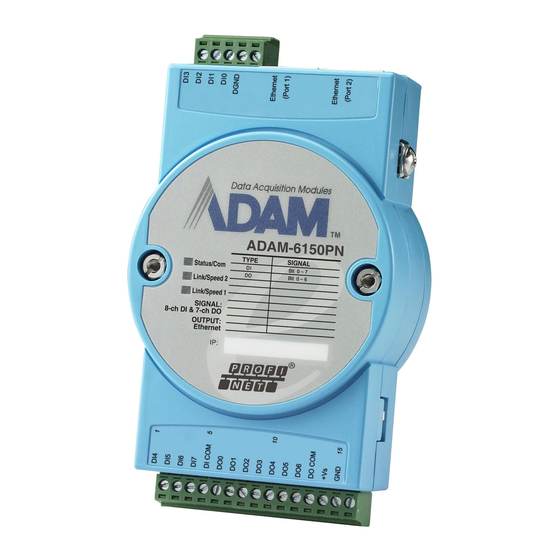
I/O modules for your application. ADAM-6150PN: 8-ch isolated digital input and 7-ch isolated digital output mod- ADAM-6151PN: 16-ch isolated digital input module ADAM-6156PN: 16-ch isolated digital output module Figure 3.1 ADAM-6150PN ADAM-6100PN Series User Manual... - Page 25 Figure 3.2 ADAM-6151PN Figure 3.3 ADAM-6156PN ADAM-6100PN Series User Manual...
-
Page 26: Specifications
Power Consumption: 2.4 W @ 24 V Power Reversal Protection (30V Max.) Operating Humidity: 20 ~ 95% RH (non-condensing) Storage Humidity: 0 ~ 95% RH (non-condensing) Operating Temperature: -10 ~ 70°C Storage Temperature: -20 ~ 80°C ADAM-6100PN Series User Manual... -
Page 27: Switch Settings
3.1.3 Switch Settings ADAM-6150PN: Switch Position DI Channel Ch3 Dry Contact (Default) Wet contact ADAM-6151PN: Switch Position DI Channel Ch3 Switch Position DI Channel Ch11 Ch10 Ch9 Ch15 Ch14 Ch13 Ch12 Dry Contact (Default) Wet contact ADAM-6100PN Series User Manual... -
Page 28: Application Wiring
3.1.4 Application Wiring Isolated Digital Input - Dry Contact Isolated Digital Input - Wet Contact ADAM-6100PN Series User Manual... - Page 29 Isolated Digital Output (ADAM-6150PN) Isolated Digital Output (ADAM-6156PN) ADAM-6100PN Series User Manual...
-
Page 30: Relay Modules
500 VAC (50/60 Hz) Mechanism: 20,000,000 operations Relay on time: 7 ms Relay off time: 3 ms Contact Resistance: 30 mΩ (max.) Insulation Resistance: 1 GΩ at 500 V FSV Safety Function ADAM-6100PN Series User Manual... -
Page 31: Jumper Settings
Jumper Settings Relay Ch0 Configuration Normally Open (Default) Normally Closed Note! Users need to separate two PC boards to set the jumpers of the ADAM- 6160PN. Note! The two jumpers for CN7 must be moved together. ADAM-6100PN Series User Manual... -
Page 32: Analog I/O Modules
Current Range Resolution Range Resolution ±150 mV 16 bit ±20mA 15 bit ±500 mV 16 bit 0~20 mA 14 bit ±1 V 16 bit 4~20 mA 14 bit ±5 V 16 bit ±10 V 16 bit ADAM-6100PN Series User Manual... - Page 33 • Storage Humidity: 0 ~ 95% RH (non-condensing) • Operating Temperature: -10 ~ 70°C • Storage Temperature: -20 ~ 80°C 3.3.1.3 Switch Settings SW1~SW4: Set input mode of each AI channel Switch Position Channel Current Mode Voltage Mode (Default) 3.3.1.4 Application Wiring ADAM-6100PN Series User Manual...
-
Page 34: Adam-6124Pn: 4-Ch Analog Output And 4-Ch Digital Input Module
The ADAM-6124PN is a 12-bit, 4-channel analog output module along with 4-chan- nel dry-contact digital input. It provides programmable output ranges on all channels and supports voltage and current outputs, which makes it an ideal output control solution. Figure 3.6 ADAM-6124PN ADAM-6100PN Series User Manual... - Page 35 • Power Consumption: 3 W (max.) @ 24 V • Power Reversal Protection (30V max.) • Operating Humidity: 20 ~ 95% RH (non-condensing) • Storage Humidity: 0 ~ 95% RH (non-condensing) • Operating Temperature: -10 ~ 70°C • Storage Temperature: -20 ~ 80°C ADAM-6100PN Series User Manual...
- Page 36 ADAM-6100PN Series User Manual...
-
Page 37: Chapter 4 System Configuration Guide
Chapter System Configuration Guide... -
Page 38: System Hardware Configuration
You can find the Utility installation file in the CD with your ADAM module, or link to the web site: http://www.advantech.com and click into the Download Area under Service & Support site to get the latest version of the ADAM-6100 Series ADAM.NET Utility. -
Page 39: Adam.net Utility Operation Window
3.Auto-Initial Group - If you want to have the same favorite group configuration when you exit ADAM.NET utility and launch it again, you need to check this option. 4.Exit - Exit ADAM.NET Utility. ADAM-6100PN Series User Manual... - Page 40 Modbus/TCP as communication protocol. You can launch the terminal to communicate with ADAM-6000 module by these two protocol directly. DiagAnywhere Searcher - There are multiple Advantech products installed with DiagAnywhere server, which gives user remote control ability through Ethernet.
- Page 41 Status Display area, on the right part of utility operation window, is the main screen for operation. When you select different items in Module Tree Display, Status Dis- play will change dependently. You can do all configurations and test in this area. ADAM-6100PN Series User Manual...
-
Page 42: Search Adam-6100 Modules
You can see the Firmware Version on the selected ADAM-6100 module in this tab. You can also update the firmware by clicking Download button. The latest firmware for ADAM-6100 modules is available on Advantech website: http://www.advan- tech.com ADAM-6100PN Series User Manual... - Page 43 4.3.2.2 Setting You can change IP Address, Subnet Address, and Default Gateway of selected ADAM-6100 module in this tab. You can also enable or disable DHCP function for ADAM-6100 module. ADAM-6100PN Series User Manual...
-
Page 44: I/O Module Configuration
Channel Configuration item, you can read AI values or configure setting for the specific channel you choose. Below, we will describe the All Channel Configuration and Individual Channel Configuration in more detail for ADAM-6000 I/O modules. Analog Input Module (ADAM-6015, ADAM-6017 and ADAM-6018) ADAM-6100PN Series User Manual... - Page 45 Channels Range Configuration area. Refer to Figure 5.6 below. In the Integration Time Configuration area, you can select suitable filter in the Integra- tion time combo box. After selecting appropriate filter, click the Apply button. Figure 4.5 Integration Time Configuration Area ADAM-6100PN Series User Manual...
- Page 46 With the wire burn-out detection function of ADAM-6015 and ADAM-6018, if there is no sensor connected to the input channel of ADAM-6015 or ADAM-6018 module, you can see “Burn out” characters showing in the text box of related channel. ADAM-6100PN Series User Manual...
- Page 47 You can see historical minimum analog input value in decimal, hexa- decimal, and engineer unit for all related Modbus address. If you want to re-initialize the recording, click the buttons representing the channels you want to reset. ADAM-6100PN Series User Manual...
- Page 48 If the alarm condition disappears, the alarm status will be logic low. So not only the Alarm status LED in the utility but also the specific digital output chan- nel value will change depend on the alarm condition. ADAM-6100PN Series User Manual...
- Page 49 1 LED display. You also can see the graphical historical trend of analog input channel by clicking the Trend Log button. All the operations for trend logging is the same as ADAM-6015, ADAM-6017 and ADAM-6018 module. ADAM-6100PN Series User Manual...
- Page 50 4 mA. In the top right-hand corner of the Output tab, you can control the digital output value by the DO 0 and DO 1 button. Their value will be display by the LED near the button. ADAM-6100PN Series User Manual...
- Page 51 PC is broken, channels 0 and 2 will automatically generate logic high value, while channels 1, 3, 4, 5 will automatically generate logic low value. Figure 4.12 Fail Safe Value Configuration Modbus You can see current digital input or digital output values for all related Modbus address. ADAM-6100PN Series User Manual...
- Page 52 Minimum high signal width text box. (Unit: ms) The high frequency noise will be removed by this filter. Remember to click the Apply all button for all channels or Apply this button for this specific channel to complete the configuration. ADAM-6100PN Series User Manual...
- Page 53 Frequency value text box at the bottom of the Status Display area. If you choose a digital output channel in the Individual Channel Configuration items, the Status Display area should look similar to Figure 5.15 below. ADAM-6100PN Series User Manual...
- Page 54 The text box at the right hand of the Fixed total button is used to define how many pulses you want to generate. After select the pulse output mode, click the Start or Stop button to generate or stop the pulse output. ADAM-6100PN Series User Manual...
- Page 55 Delay Time At the moment that you write logic high to the digital output channel At the moment that you write logic low to the digital output channel Figure 4.16 Low to High Delay Output Mode ADAM-6100PN Series User Manual...
- Page 56 ADAM-6100PN Series User Manual...
-
Page 57: Profinet Mapping
Appendix PROFINET Mapping Table... - Page 58 Analog Input and Analog Output Modules Each ADAM-6100 analog module will use up to 8 WORD address for its data. Each analog channel will occupy one WORD address. ADAM-6117 Name Data Type Data Format Input AI Channel 0 Unsigned 16 Bit [15…0] AI Channel 1 Unsigned 16...
- Page 59 Digital Input and Digital Output Modules Each ADAM-6100 digital module will use up to 2 BYTE address for its data. Each BYTE address will contain 8 digital channel data. ADAM‐6150 Name Data Type Data Format Input DI Channel 0...7 Unsigned 8 Bit [7…0] Output DO Channel 0...6 Unsigned 8 Bit [6…0] ADAM‐6151 Name...
- Page 60 ADAM-6100PN User Manual...
Need help?
Do you have a question about the ADAM-6100PN Series and is the answer not in the manual?
Questions and answers