Sign In
Upload
Download
Table of Contents
Contents
Add to my manuals
Delete from my manuals
Share
URL of this page:
HTML Link:
Bookmark this page
Add
Manual will be automatically added to "My Manuals"
Print this page
×
Bookmark added
×
Added to my manuals
Manuals
Brands
Circutor Manuals
Measuring Instruments
CVM-E3-MINI-ITF
Instruction manual
Circutor CVM-E3-MINI-ITF Instruction Manual
Power analyzer
Hide thumbs
1
2
3
Table Of Contents
4
5
6
7
8
9
10
11
12
13
14
15
16
17
18
19
20
21
22
23
24
25
26
27
28
29
30
31
32
33
34
35
36
37
38
39
40
41
42
43
44
45
46
47
48
49
50
51
52
53
54
55
56
57
58
59
60
61
62
63
64
65
66
67
68
69
70
71
72
73
74
75
76
77
78
79
80
81
82
83
84
85
86
87
88
89
90
91
92
93
94
95
96
97
98
99
100
101
102
103
104
105
106
107
108
109
110
111
112
113
114
115
116
117
118
119
120
page
of
120
Go
/
120
Contents
Table of Contents
Bookmarks
Table of Contents
Safety Precautions
Disclaimer
Table of Contents
Contents
Revision Log
Symbols
1�- Verification Upon Reception
2�- Product Description
3�- Device Installation
3�1�- Prior Recommendations
3�2�- Installation
3�3�- PANEL MOUNTING ACCESSORY (72 X 72 MM)
3�4�- CVM-E3-Mini-Flex: Rogowski Sensors
3�5�- Device Terminals
3�5�1�- Models CVM-E3-Mini-Itf and CVM-E3-Mini-MC
3�5�2�- Model CVM-E3-Mini-Flex
3�5�3�- MODELS CVM-E3-MINI-ITF-Wieth and CVM-E3-MINI-MC-Wieth
3�5�4�- MODEL CVM-E3-MINI-FLEX-Wieth
3�6�- Connection Diagram
AND CVM-E3-MINI-ITF-Wieth
AND CVM-E3-MINI-MC-Wieth
AND CVM-E3-MINI-FLEX-Wieth
AND CVM-E3-MINI-ITF-Wieth
AND CVM-E3-MINI-MC-Wieth
AND CVM-E3-MINI-FLEX-Wieth
3�6�7�- Measuring Three-Phase Networks with a 3-Wire Connection and
3�6�8�- Measuring Three-Phase Networks with a 3-Wire Connection and
CVM-E3-MINI-ITF-Wieth
AND CVM-E3-MINI-MC-Wieth
AND CVM-E3-MINI-FLEX-Wieth
3�6�12�- Measuring Single-Phase Networks, Phase to Phase, with a 2-Wire
CONNECTION: CVM-E3-MINI-ITF and CVM-E3-MINI-ITF-Wieth
3�6�13�- Measuring Single-Phase Networks, Phase to Phase, with a 2-Wire
CONNECTION: CVM-E3-MINI-MC and CVM-E3-MINI-MC-Wieth
3�6�14�- MEASURING SINGLE-PHASE NETWORKS, PHASE to PHASE, with a 2-WIRE CONNECTION: CVM-E3-MINI-FLEX and CVM-E3-MINI-FLEX-Wieth
3�6�15�- Measuring Single-Phase Networks, Phase to Neutral, with a 2-Wire
CONNECTION: CVM-E3-MINI-ITF and CVM-E3-MINI-ITF-Wieth
3�6�16�- Measuring Single-Phase Networks, Phase to Neutral, with a 2-Wire
CONNECTION: CVM-E3-MINI-MC and CVM-E3-MINI-MC-Wieth
3�6�17�- MEASURING SINGLE-PHASE NETWORKS, PHASE to NEUTRAL, with a 2-WIRE CONNECTION: CVM-E3-MINI-FLEX and CVM-E3-MINI-FLEX-Wieth
4�- Operation
4�1�- Measuring Parameters
4�2�- Keyboard Functions
4�3�- Display
4�4�- Led Indicators
4�5�- DIGITAL INPUT (Models CVM-E3-MINI-XXX)
4�6�- DIGITAL OUTPUT (Models CVM-E3-MINI-XXX)
5�- Display
5�1�- Analyzer Profile
5�1�1�- Maximum Values
5�1�2�- Minimum Values
5�1�3�- Maximum Demand
5�1�4�- Harmonics
5�1�5�- Detection of Incorrect Connection and Incorrect Direction of Rotation 4
Profile
5�3�- Device Information Screens
5�4�- DIGITAL INPUT and OUTPUT STATUS SCREEN (Models CVM-E3-MINI-XXX)
5�5�- Ethernet - Wi-Fi - Bluetooth ® Communications Screens
5�5�1� ETHERNET COMMUNICATIONS: Dhcp CONFIGURATION
5�5�2� Ethernet Communications: Ip Adress
5�5�3� Ethernet Communications: Ip Mask
5�5�4� Ethernet Communications: Gateway
5�5�5� Ethernet Communications: Mac Address
5�5�6� Wi-Fi Communications: Ip Address
5�5�7� Wi-Fi Communications: Mac Address
5�5�8� Wi-Fi Communications: Signal Level
Communications: Name
6�- Configuration
6�1�- Primary Voltage
6�2�- Secondary Voltage
6�3�- Primary Current
6�4�- Secondary Current (Model CVM-E3-Mini-Itf)
6�5�- Flex Sensor
6�6�- Number of Quadrants
6�7�- Measurement Convention
6�8�- Measurement System
6�9�- Maximum Demand Integration Period
6�10�- Deleting Maximum Demand
6�11�- Deleting Maximum and Minimum Values
6�12�- Deleting Energy Values
6�13�- Enable Harmonics Display Screen
Carbon Emission Ratio of Consumed Energy
6�16�- Cost Ratio of Consumed Energy
Carbon Emission Ratio of Generated Energy
6�17�- Cost Ratio of Generated Energy
6�18�- Programming Alarm : Digital Output T1
6�18�1� Maximum Value
6�18�2� Minimum Value
6�18�3� Connection Time Delay
6�18�4� Hysteresis Value
6�18�5� Latch
6�18�6� Disconnection Time Delay
6�18�7� Contact Status
6�18�8� Kilowatts Per Pulse
6�18�9� Pulse Width
6�19�- OPERATING MODE of DIGITAL INPUT (Models CVM-E3-MINI-XXX)
6�20�- TARIFF SELECTION (Models CVM-E3-MINI-XXX-Wieth)
6�21�- Backlight, Turning on the Backlit Display
6�22�- RS-485 COMMUNICATIONS (Models CVM-E3-MINI-XXX)
6�22�1�- Modbus Protocol: Baud Rate
6�22�2�- Modbus Protocol: Peripheral Number
6�22�3�- Modbus Protocol : Parity
6�22�4�- Modbus Protocol : Data Bits
6�22�5�- Modbus Protocol : Stop Bits
6�22�6�- Bacnet PROTOCOL : BAUD RATE
6�22�7�- Bacnet PROTOCOL : ID
6�22�8�- Bacnet PROTOCOL : MAC ADDRESS
6�23�- Locking the Programming
6�23�1�- Password
7�- CVM-E3-Mini-XXX : Rs-485 Communications
7�1�- Connections
7�2�- Modbus Protocol
7�2�1�- READING EXAMPLE : Funtion 0X04
7�2�2�- WRITING EXAMPLE : Funtion 0X05
7�3�- Modbus Commands
7�3�1� Measurement Variables
7�3�2� Energy Variables
7�3�3� Voltage and Current Harmonics
7�3�4� Deleting Parameters
7�3�5� Power Status
7�3�6� Detection of Incorrect Direction of Rotation
7�3�7� Device Configuration Variables
7�4�- Bacnet PROTOCOL
7�4�1�- Mapa Pics
8�- CVM-E3-Mini-XXX-Wieth : Communications
8�1�- Usage Environment and Health
8�2�- Wi-Fi COMMUNICATIONS
Communications
8�4�- Mobile App
8�5�- Configuration Web Page
9�- Technical Features
10�- Maintenance and Technical Service
11�- Guarantee
12�- Ce Certificate
Annex A�- Configuration Menus
Advertisement
Quick Links
Download this manual
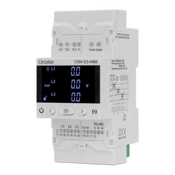
Power analyzer
CVM-E3-MINI
INSTRUCTION MANUAL
(M170B01-03-20D)
Table of
Contents
Previous
Page
Next
Page
1
2
3
4
5
Advertisement
Table of Contents
Need help?
Do you have a question about the CVM-E3-MINI-ITF and is the answer not in the manual?
Ask a question
Questions and answers
Related Manuals for Circutor CVM-E3-MINI-ITF
Measuring Instruments Circutor CVM-E3-MINI Instruction Manual
Power analyzer (124 pages)
Measuring Instruments Circutor CVM-E3-MINI-MC Instruction Manual
Power analyzer (120 pages)
Measuring Instruments Circutor CVM-B100 Instruction Manual
Power analyzer (330 pages)
Measuring Instruments Circutor CVM-B100 Instruction Manual
Power analyzer (322 pages)
Measuring Instruments Circutor CVM 96 Instruction Manual
Cvm 96 series supply network analyzer (50 pages)
Measuring Instruments Circutor CVMk2 Manual
Power and network quality analyzer (9 pages)
Measuring Instruments Circutor CVM-MINI SERIES Instruction Manual
Power analyzer (26 pages)
Measuring Instruments Circutor CVM-C4 Series Instruction Manual
Power analyzer (70 pages)
Measuring Instruments Circutor CVM-C4 Instruction Manual
Power analyzer (70 pages)
Measuring Instruments Circutor CVM-A1000 Instruction Manual
Power analyzer (378 pages)
Measuring Instruments Circutor CVM-C5 Series Instruction Manual
Power analyzer (54 pages)
Measuring Instruments Circutor CVM-D41 DC Instruction Manual
(56 pages)
Measuring Instruments Circutor CVM-C11 Instruction Manual
Power analyzer (106 pages)
Measuring Instruments Circutor CVM-C11 Instruction Manual
Power analyzer (134 pages)
Measuring Instruments Circutor CVM-B150-ITF-HF Instruction Manual
Power analyzer (304 pages)
Measuring Instruments Circutor CVMk Series Instruction Manual
Supply network analyzer (64 pages)
This manual is also suitable for:
Cvm-e3-mini
Cvm-e3-mini-itf-wieth
Cvm-e3-mini-mc
Cvm-e3-mini-mc-wieth
Cvm-e3-mini-flex
Cvm-e3-mini-flex-wieth
Table of Contents
Print
Rename the bookmark
Delete bookmark?
Delete from my manuals?
Login
Sign In
OR
Sign in with Facebook
Sign in with Google
Upload manual
Upload from disk
Upload from URL


Need help?
Do you have a question about the CVM-E3-MINI-ITF and is the answer not in the manual?
Questions and answers