Table of Contents
Advertisement
Quick Links
Advertisement
Table of Contents

Related Manuals for Circutor CVM-MINI SERIES


Summary of Contents for Circutor CVM-MINI SERIES
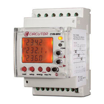
- Page 1 POWER ANALYZER CVM-MINI SERIES INSTRUCTION MANUAL M98174001-03-19A CIRCUTOR, SA...
-
Page 2: Table Of Contents
CONTENTS 1 BASIC INSTRUCTIONS ......................3 Checks on receipt......................3 Main features ........................3 Electrical parameters ......................3 Other features ........................4 Available models ......................4 2 INSTALLATION AND START-UP ....................5 Installation ........................5 2.1.1 Power supply voltage ....................5 2.1.2 Maximum voltage in the voltage measurement circuit ........... -
Page 3: Basic Instructions
1 BASIC INSTRUCTIONS This manual is designed to familiarise the user with operating the CVM-MINI power analyzer in order to get the best from its features. 1.1 Checks on receipt. Please check the following points on receipt of the analyzer: •... -
Page 4: Other Features
PARAMETER UNIT L1 L2 L3 Phase-neutral voltage V f-n • • • Phase-phase voltage V f-f • • • Current • • • •• Frequency • Active power • • • • Reactive power L kvarL • • • • Reactive power C kvarC •... -
Page 5: Installation And Start-Up
2 INSTALLATION AND START-UP This manual contains information and warnings about the analyzer which must be followed to guarantee the proper operation of all instrument functions and to maintain it in a safe condition. The analyzer must not be switched on until it is finally connected to the electrical board. -
Page 6: Operating Conditions
2.1.6 Operating conditions Operating temperature: -10 ºC / +50ºC Relative humidity: 5 to 95 % RH (without condensation) Altitude: Up to 2000 metres 2.1.7 Safety Designed for category III installations, 300 V ∼ AC (EN 61010). Class II double insulation against electric shock protection. 2.2 Start-up The equipment is mounted on a DIN rail 46277 (EN 50022). -
Page 7: Connection Diagrams
2.2.2 Connection diagrams Figure 2. [4-wire / 3-wire - Low Voltage] Figure 3. [2 voltage transformers - Figure 4. [2 voltage transformers - 3 current transformers] 2 current transformers] 3 OPERATING MODE When power is supplied to the CVM-MINI, the equipment will start its software interface on the screen showing the version of the firmware and its setting. -
Page 8: Keypad
3.1 Keypad The keypad comprises a total of seven silicon buttons which are used to set the equipment. Some buttons have a rapid access function, i.e. entering the Set Up interface is not required. Only the rapid access key needs to be pressed to run the function. -
Page 9: Default Display
3.2.1 Default display 389.5 5 0 3 , 2 1 1 7 , 2 229.5 389 8 229.8 5 7 0 . 9 1 3 2 , 5 390.1 230.1 5 5 0 . 8 1 2 8 , 5 Figure 7. -
Page 10: Led Indicators
3.2.2 LED Indicators The CVM-MINI power analyzer is supplied with two LED indicators which give information on the status of: FUNCTION The slow flashing of the LED CPU shows that the equipment has auxiliary power supply and is operative. The rapid flashing of the LED CPU shows that there is an internal problem with the start up software. -
Page 11: Transformation Ratios
4.1.1 Transformation Ratios This menu accesses the voltage and current ratios and the voltage and current primary and secondary may be changed. 4.1.1.1 Voltage primary value The display shows ”set PriU” followed by six digits; these allow the setting of the transformer voltage primary. -
Page 12: Current Secondary Value
When the last digit has been changed, press to move back to the first digit, allowing the previously set values to be changed again. To enter the data and access the next setting step, press s e t p r i a 0 0 0 0 5 Figure 32. -
Page 13: Power Demand Meter Parameterisation
To select one of the two display options (2 or 4 measurement quadrants), press key and the two options will alternate. Once the required option is selected, press the key to enter the data and access the next setting step. s e t s e t q u a d... -
Page 14: Clearing Power Demand Meter Value
4.1.3.3 Clearing power demand meter value To clear or save maximum demand, press the key and the two options will alternate. Once the required option is selected, press the key to enter the data and access the next setting step. Cl r Cl r y e s... -
Page 15: Backlight (Backlit Display)
4.1.4.3 Backlight (Backlit display) The time in which the back lighting will be on after the last use is set by using the keypad in this menu. The display is permanently on if 00 is set. 4.1.5 Clearing energy meter values Clearing energy meters refers to the four consumed or imported energy meters. -
Page 16: Impulse Per N Kw·h Or Kvar·h Consumed Or Generated
4.1.7.1 Impulse per n KW·h or Kvar·h consumed or generated In order to generate an impulse for consumed n kW·h, the energy meter to be used has to be selected: PARAMETER SYMBOL CODE Active energy III kW·h III Inductive reactive energy III KvarL·h III Capacitive reactive energy III KvarC·h III... - Page 17 PARAMETER PHASE SYMBOL CODE Phase-neutral voltage Current Active power kW 1 Reactive power L/C KvarL/C 1 Apparent power kV·A Power factor PF 1 % THD V THD V1 % THD A THD A1 Phase-neutral voltage Current Active power kW 2 Reactive power L/C KvarL/C 2 Apparent power...
- Page 18 PARAMETER SYMBOL CODE Phase-neutral voltage V1 / V2 / V3 Current A1 / A2 / A3 Active power kW1 / kW2 / kW3 Reactive power Kvar1 / kvar2 / kvar3 Apparent power kV·A1 / kV·A2 / kV·A3 Power factor PF1 / PF2 / PF3 Phase-phase voltage V12 / V23 / V31 % THD V...
-
Page 19: Communication Set-Up
4.2 Communication Set-up One or more CVM-MINI instruments may be connected to a computer or PLC in order to automate a production process or an energy control system. As well as the usual operation of each instrument, this system may centralize data at one single point; for this reason the CVM-MINI has an RS-485 communication output. -
Page 20: Peripheral Number
s e t s e t Cd e f Cd e f y e s Figure 53. Non-standard communication Figure 54. Predefined communication parameters parameters 4.2.2 Peripheral number The peripheral number varies between 0 and 255 (0 and FF in hexadecimal). To write or change the number of the peripheral, repeatedly press the increasing the value of the digit which is flashing at the time. -
Page 21: Data Bits
s e t Pa r i Figure 57. Parity 4.2.5 Data bits 7 or 8 data bits may be selected; to select the number of bits, press the and the two options will alternate in turn. Once the required option is selected, press the key to enter the data and access the next setting step. -
Page 22: Appendix - Cvm-Mini-Itf-Har-Rs485-C2 Series
5 APPENDIX – CVM-MINI-ITF-HAR-RS485-C2 SERIES The CVM-MINI Series has an analyzer for the harmonic content up to the 15 harmonic in voltage and current, showing the content on the LCD display. Therefore, the HAR has a high number of display screens, where the value of the current and voltage fundamental and the content of each harmonic may be seen. -
Page 23: Modbus Rtu Protocol
6 MODBUS RTU PROTOCOL The CVM-MINI power analyzer communicates using the MODBUS© protocol. In the MODBUS protocol the RTU (Remote terminal Unit) mode is used; each 8-bit per byte in a message contains two 4-bits hexadecimal characters. The format for each byte in RTU mode is: Code 8 bit binary, hexadecimal 0-9, A-F. - Page 24 PARAMETER SYMBOL Instant Maximum Minimum Units Active power III kW III 1E-1F 7E-7F DE-DF Inductive power III KvarL III 20-21 80-81 E0-E1 Capacitive power III KvarC III 22-23 82-83 E2-E3 Cos φ III Cos φ III 24-25 84-85 E4-E5 x 100 Power factor III PF III 26-27...
- Page 25 MODBUS VARIABLES * Recordings available in HAR model PARAMETER SYMBOL Units Harmonic content in VOLTAGE RMS current 2AE-2AF 2CC-2CD 2EA-2EB Vx10 Harmonic 2 2B0-2B1 2CE-2CF 2EC-2ED Harmonic 3 2B2-2B3 2D0-2D1 2EE-2EF Harmonic 4 2B4-2B5 2D2-2D3 2F0-2F1 Harmonic 5 2B6-2B7 2D4-2D5 2F2-2F3 Harmonic 6 2B8-2B9...
-
Page 26: Rs485 Connection Diagram
7 TECHNICAL SERVICE In the event of any equipment failure or any operational queries please contact the technical service of CIRCUTOR S.A. CIRCUTOR S.A. - After sales service. Vial Sant Jordi, s/n 08232 - Viladecavalls. Tel. – 902 449 459 (Spain) / +34 937 452 919 ( Out of Spain) E-mail - sat@circutor.com...
Need help?
Do you have a question about the CVM-MINI SERIES and is the answer not in the manual?
Questions and answers