Table of Contents
Advertisement
Quick Links
Advertisement
Table of Contents

Related Manuals for Circutor CVM-C4


Summary of Contents for Circutor CVM-C4
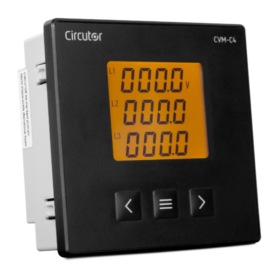
- Page 1 Power analyzer CVM-C4 INSTRUCTION MANUAL (M267B01-03-21C)
- Page 2 CVM-C4 Instruction Manual...
-
Page 3: Safety Precautions
CIRCUTOR, SA reserves the right to make modifications to the device or the unit specifications set out in this instruction manual without prior notice. CIRCUTOR, SA on its web site, supplies its customers with the latest versions of the device specifica- tions and the most updated manuals. -
Page 4: Table Of Contents
CVM-C4 CONTENTS SAFETY PRECAUTIONS ���������������������������������������������������������������������������������������������������������������������������������������������������������3 DISCLAIMER ��������������������������������������������������������������������������������������������������������������������������������������������������������������������������3 CONTENTS �����������������������������������������������������������������������������������������������������������������������������������������������������������������������������4 REVISION LOG �����������������������������������������������������������������������������������������������������������������������������������������������������������������������6 SYMBOLS �������������������������������������������������������������������������������������������������������������������������������������������������������������������������������6 1 �- VERIFICATION UPON RECEPTION ����������������������������������������������������������������������������������������������������������������������������������� 7 2 �- PRODUCT DESCRIPTION ������������������������������������������������������������������������������������������������������������������������������������������������ 7 3 �- DEVICE INSTALLATION ���������������������������������������������������������������������������������������������������������������������������������������������������8 3�1�- PRIOR RECOMMENDATIONS ������������������������������������������������������������������������������������������������������������������������������������8 3�2�- INSTALLATION ���������������������������������������������������������������������������������������������������������������������������������������������������������9 3�3�- DEVICE TERMINALS ����������������������������������������������������������������������������������������������������������������������������������������������� 10 3�4�- CONNECTION DIAGRAM ������������������������������������������������������������������������������������������������������������������������������������������11... - Page 5 CVM-C4 7�1�- CONNECTIONS �������������������������������������������������������������������������������������������������������������������������������������������������������� 51 7�2�- MODBUS PROTOCOL ����������������������������������������������������������������������������������������������������������������������������������������������52 7�2�1� READING EXAMPLE: FUNCTION 0x01� ��������������������������������������������������������������������������������������������������������������52 7�2�2� EXAMPLE OF OPERATION OF THE REMOTE CONTROL: FUNCTION 0x05� ������������������������������������������������������52 7�3�- MODBUS COMMANDS ��������������������������������������������������������������������������������������������������������������������������������������������53 7�3�1 �- MEASUREMENT VARIABLES AND DEVICE STATUS �����������������������������������������������������������������������������������������53 7�3�2�- OUTPUT RELAYS ����������������������������������������������������������������������������������������������������������������������������������������������55 7�3�3�- DIGITAL INPUTS �����������������������������������������������������������������������������������������������������������������������������������������������56...
-
Page 6: Revision Log
CVM-C4 REVISION LOG Table 1: Revision log Date Revision Description 11/19 M267B01-03-19A First Version Changes in the following sections: 02/20 M267B01-03-20A 3.4. - 8. Changes in the following sections: 07/20 M267B01-03-20B 3.4.2. - 7.1 Changes in the following sections: 09/20 M267B01-03-20C 4.1. -
Page 7: Verification Upon Reception
CIRCUTOR's after-sales service 2 .- PRODUCT DESCRIPTION The CVM-C4 is a device that measures, calculates and displays the main electrical parameters in sin- gle-phase and three-phase networks. The device has RS-485 communications, relay outputs, impulse outputs and digital inputs. -
Page 8: Device Installation
The CVM-C4 device must be installed by authorised and qualified staff. The power supply plug must be disconnected and measurement systems switched off before handling, altering the connections or replacing the device. -
Page 9: 3�2�- Installation
CVM-C4 3�2�- INSTALLATION Terminals, opening covers or removing elements can expose parts that are hazard- ous to the touch while the device is powered. Do not use the device until it is fully installed. The device should be installed inside an electric panel or enclosure, and panel-mounted. -
Page 10: 3�3�- Device Terminals
An incorrect type of con- nection or an error in phase sequence may cause measurement errors. 3�3�- DEVICE TERMINALS Table 4: List of CVM-C4 terminals Device terminals 1: L/+, Power supply... -
Page 11: 3�4�- Connection Diagram
CVM-C4 3�4�- CONNECTION DIAGRAM 3�4�1�- THREE-PHASE NETWORK MEASURING WITH 4-WIRE CONNECTION Alimentación Auxiliar Power Supply 47 48 49 50 59 70 71 72 15 16 17 18 Power Supply U2 U3 S2 S1 S2 S1 12 13 CARGA / LOAD Figure 5: Three-phase network measuring with 4-wire connection�... -
Page 12: 3�4�2�- Three-Phase Network Measuring With 3-Wire Connection
CVM-C4 3�4�2�- THREE-PHASE NETWORK MEASURING WITH 3-WIRE CONNECTION Alimentación Auxiliar Power Supply 47 48 49 50 59 70 71 72 15 16 17 18 Power Supply S2 S1 S2 S1 12 13 CARGA / LOAD Figure 6: Three-phase network measuring with 3-wire connection (Connection 1) Alimentación Auxiliar... - Page 13 CVM-C4 Alimentación Auxiliar Power Supply 47 48 49 50 59 70 71 72 15 16 17 18 Power Supply U2 U3 S2 S1 S2 S1 12 13 CARGA / LOAD Figure 8: Three-phase network measuring with 3-wire connection (Connection 3)
-
Page 14: 4�- Operation
CVM-C4 4.- OPERATION 4�1�- MEASURING PARAMETERS The CVM-C4 is a four-quadrant power analyzer (consumption and generation) that operates according to the IEC measurement convention ( Figure 9 Operation in the 4 quadrants (Q1, Q2, Q3, Q4) cos φ values in the receiver oper >... -
Page 15: 4�2�- Display
Data area Units and symbols area Figure 10: Display CVM-C4� The data area, which displays all the values measured by the device. The units and symbols area, which displays the different statuses, units and device information Table 6 Table 6: Display icons�... -
Page 16: 4�3�- Keyboard Functions
CVM-C4 4�3�- KEYBOARD FUNCTIONS The CVM-C4 has 3 keys that allow you to browse through and program the device, Table 7 and Table 8 Display screens: Table 7: Keyboard function: Display screens� Keystroke Previous screen. Next screen. Long keystroke (> 3s): Accesses the configuration menu ... -
Page 17: 4�5�- Energy Impulse Outputs
CVM-C4 4�5�- ENERGY IMPULSE OUTPUTS Salidas de pulsos de energía Energy pulse outputs The device features energy impulse outputs (terminals 47, 48, 49 and 50 in Figure 12 Figure 12: Energy impulse outputs The type of energy impulses is selected in section “6.5.1.- ENERGY ACCUMULATION MODE”. -
Page 18: 4�6�- Digital Inputs
�������� �������� 1 �������� CVM-C4 �������� �������� 2 �������� �������� �������� 1 �������� �������� �������� 2 �������� Note: The device calculates and displays the active and reactive energy, but the energy impulse output is only active energy. 1�������� �������� ℎ... -
Page 19: 5�- Display
CVM-C4 5.- DISPLAY The CVM-C4 has up to 24 display screens depending on the measurement system, see “6.1.1.- MEASUREMENT SYSTEM" 5�1�- SINGLE-PHASE NETWORK MEASURING The CVM-C4 has 15 display screens in the single-phase network measurement system, Table 9 Use the keys to browse through the different screens. - Page 20 CVM-C4 Table 9 (Continued)� Display menu: Single-phase network measuring Display menu: Single-phase network measuring Ʃ 5700 Active Power (W) Ʃ 2200 Reactive power (var) Ʃ 2200 Apparent power (VA) Ʃ 0980 Power factor Energy Accumulation Mode: Energy Accumulation Mode: EPit...
- Page 21 CVM-C4 Table 9 (Continued)� Display menu: Single-phase network measuring Display menu: Single-phase network measuring Energy Accumulation Mode: Energy Accumulation Mode: EP - EP2t 1620 1620 0300 0300 Total negative active energy (kWh) Total positive active energy, Tariff 2 (kWh) Energy Accumulation Mode:...
-
Page 22: 5�2�- Three-Phase Network Measuring With 4-Wire Connection
Note: If a display screen shows , check the programming of the transformation ratios. 5�2�- THREE-PHASE NETWORK MEASURING WITH 4-WIRE CONNECTION The CVM-C4 has 24 display screens in the three-phase network measurement system with a 4-wire connection, Table 10 Use the keys to browse through the different screens. - Page 23 CVM-C4 Table 10: Display menu: Three-phase network measuring with 4-wire connection� Display menu: Three-phase network measuring with 4-wire connection� 2206 2207 2208 Phase-Neutral Voltage (V / kV) 3800 L1-2 3801 L2-3 3803 L3-1 Phase-Phase Voltage (V / kV) Current (A / kA)
- Page 24 CVM-C4 Table 10 (Cont�)� Display menu: Three-phase network measuring with 4-wire connection� Display menu: Three-phase network measuring with 4-wire connection� 6805 6806 6807 Reactive power per phase (var) 7808 7817 7815 Apparent power per phase (VA) Ʃ 5700 Total Active Power (W) Ʃ...
- Page 25 CVM-C4 Table 10 (Cont�)� Display menu: Three-phase network measuring with 4-wire connection� Display menu: Three-phase network measuring with 4-wire connection� 0932 0931 0930 Power factor per phase 0932 Ʃ 0980 Total Power Factor Energy Accumulation Mode: Energy Accumulation Mode: EPit...
- Page 26 CVM-C4 Table 10 (Continued)� Display menu: Three-phase network measuring with 4-wire connection� Display menu: Three-phase network measuring with 4-wire connection� Energy Accumulation Mode: Energy Accumulation Mode: E92t Eq - VARh VARh 1500 1500 2003 2005 Total negative reactive energy (kvarh)
- Page 27 CVM-C4 Table 10 (Cont�)� Display menu: Three-phase network measuring with 4-wire connection� Display menu: Three-phase network measuring with 4-wire connection� 0305 THD Current L2 0311 THD Current L3 Status of digital inputs 1, status of digital input 1: flashes when the input has been activated.
-
Page 28: 5�3 Three-Phase Network Measuring With A 3-Wire Connection
CVM-C4 5�3 THREE-PHASE NETWORK MEASURING WITH A 3-WIRE CONNECTION The CVM-C4 has 18 display screens in the three-phase network measurement system with a 3-wire connection, Table 11 Use the keys to browse through the different screens. The display screens can change automatically depending on the time programmed in the section ”. - Page 29 CVM-C4 Table 11 (Cont�): Display menu: Three-phase network measuring with 3-wire connection� Display menu: Three-phase network measuring with 3-wire connection� Ʃ 2200 Total Reactive Power� (var) Ʃ 2200 Total Apparent Power (VA) Ʃ 0980 Total Power Factor Energy Accumulation Mode:...
- Page 30 CVM-C4 Table 11 (Continued): Display menu: Three-phase network measuring with 3-wire connection� Display menu: Three-phase network measuring with 3-wire connection� Energy Accumulation Mode: Energy Accumulation Mode: E91t VARh VARh 3002 3002 0102 0102 Total positive reactive energy (kvarh) Total positive reactive energy, Tariff 1 (kvarh)
- Page 31 CVM-C4 Table 11 (Cont�)� Display menu: Three-phase network measuring with 3-wire connection� Display menu: Three-phase network measuring with 3-wire connection� 0305 THD Current L2 0311 THD Current L3 Status of digital inputs 1, status of digital input 1: flashes when the input has been activated.
-
Page 32: 6�- Configuration
Cun4 1003 Software version 1906 Figure 14: CVM-C4 configuration menu� From any screen of the configuration menus, if no key is pressed for 1 minute, the device leaves the configuration menu and returns to the display screen. Note: In you can see the complete configuration menu. - Page 33 CVM-C4 Before accessing the configuration menu, it is necessary to enter the access password. ProG CodE CodE 2206 >3s >3s 2207 0000 0001 2208 >3s inpt Figure 15: Access to the configuration menu in the programming mode� Use the key to modify the value of the flashing digit.
-
Page 34: 6�1�- Configuration Of The Input
CVM-C4 6�1�- CONFIGURATION OF THE INPUT shows the input configuration menu from which the measurement system and the primary Figure 16 and secondary current and voltage are configured. inpt inpt >3s Measurement system inpt inpt >3s pt 1 pt 1... -
Page 35: 6�1�2�- Primary Voltage
CVM-C4 With a long keystroke, press to validate the option. Use the keys to browse through the menu screens. 6�1�2�- PRIMARY VOLTAGE This screen is used to configure the value of the primary voltage. inpt inpt >3s pt 1 pt 1... -
Page 36: 6�1�4�- Primary Current
CVM-C4 Use the keys to browse through the menu screens. 6�1�4�- PRIMARY CURRENT This screen is used to configure the value of the primary current. inpt inpt >3s Ct 1 Ct 1 0005 0005 With a long keystroke (>3s), press to access the value's configuration. -
Page 37: 6�1�6�- Save Configuration
CVM-C4 6�1�6�- SAVE CONFIGURATION This screen is used to save the device's configuration. SAuE SAuE >3s With a long keystroke (>3s), press to access the value's configuration. Use the keys to browse through the different options: , to not save the configuration. -
Page 38: 6�2�1�- Modbus Address
CVM-C4 6�2�1�- MODBUS ADDRESS This screen is used to configure the device's modbus address. Con1 Con1 >3s Addr Addr 0001 0001 With a long keystroke (>3s), press to access the value's configuration. Use the key to modify the value of the flashing digit. -
Page 39: 6�2�3�- Data Format
CVM-C4 6�2�3�- DATA FORMAT This screen is used to configure the data format. Con1 Con1 >3s dAtA dAtA With a long keystroke (>3s), press to access the value's configuration. Use the keys to browse through the different options: n.8.1 , no parity, 8 data bits, 1 stop bit E.8.1,... -
Page 40: 6�3�- Relay Output 1
CVM-C4 6�3�- RELAY OUTPUT 1 shows the configuration menu of relay output 1. Figure 18 do-1 do-1 >3s Relay mode nodE nodE do-1 do-1 >3s tinE tinE Relay pulse duration 0000 0000 do-1 do-1 >3s Alarm parameter itEn itEn Un H... -
Page 41: 6�3�2�- Relay Pulse Duration
CVM-C4 , relay output 1 is disabled. , remote control output. , alarm output. With a long keystroke, press to validate the option. Use the keys to browse through the menu screens. 6�3�2�- RELAY PULSE DURATION Note: Visible variable if the relay operating mode has been configured as a remote control output or alarm output. -
Page 42: 6�3�3�- Alarm Parameter
CVM-C4 6�3�3�- ALARM PARAMETER Note: Visible variable if the relay operating mode has been configured as an alarm output. This screen is used to configure the parameter on which the alarm will be activated. do-1 do-1 >3s itEn itEn Un H Un H With a long keystroke (>3s), press... -
Page 43: 6�3�4�- Alarm Value
CVM-C4 6�3�4�- ALARM VALUE Note: Visible variable if the relay operating mode has been configured as an alarm output. Not visible if the alarm parameter is the digital inputs ( di-1, di-0, d2-1, d2-0). The display value after which the alarm will be activated is configured on this screen. -
Page 44: 6�3�5�- Hysteresis
CVM-C4 6�3�5�- HYSTERESIS Note: Visible variable if the relay operating mode has been configured as an alarm output. Not visible if the alarm parameter is the digital inputs ( di-1, di-0, d2-1, d2-0). This screen is used to configure the hysteresis value, i.e., the difference between the alarm connection and disconnection value. -
Page 45: 6�3�6�- Connection Delay
CVM-C4 6�3�6�- CONNECTION DELAY Note: Visible variable if the relay operating mode has been configured as an alarm output. This screen is used to configure the alarm connection delay do-1 do-1 >3s dELy dELy 0000 0000 With a long keystroke (>3s), press to access the value's configuration. -
Page 46: 6�5�- System Configuration
CVM-C4 6�5�- SYSTEM CONFIGURATION shows the system configuration menu. Figure 19 >3s nodE nodE Energy accumulation mode >3s Cyclic display >3s liGH LiGH Display Backlight 0000 0000 >3s diSP diSp Initial display screen >3s CodE CodE Access Password 0001 0001 >3s... -
Page 47: 6�5�2�- Cyclic Display
CVM-C4 , the active and reactive energy accumulate in consumption (positive). Tariffs 1 and 2 are displayed for each of them. With a long keystroke, press to validate the option. Use the keys to browse through the menu screens. 6�5�2�- CYCLIC DISPLAY The display screens can change automatically or not. -
Page 48: 6�5�4�- Initial Display Screen
CVM-C4 6�5�4�- INITIAL DISPLAY SCREEN In this section the initial display screen is configured. >3s diSP diSp With a long keystroke (>3s), press to access the value's configuration. Use the keys to browse through the different options: , voltage screen. -
Page 49: 6�5�6�- Light Alarm
CVM-C4 6�5�6�- LIGHT ALARM If the device's input voltage or current value is higher than a % of the nominal value, the device can make the digits on the display start flashing, in the form of a light alarm. >3s With a long keystroke (>3s), press... -
Page 50: 6�6�- Clearing Parameters
CVM-C4 6�6�- CLEARING PARAMETERS shows the configuration menu for clearing parameters. Figure 20 >3s Clearing energies CLrE CLrE SAuE SAuE >3s Save con guration Figure 20: Configuration menu for clearing parameters� 6�6�1�- CLEARING ENERGIES This screen is used to configure clearing or not energy parameters. -
Page 51: 7�- Rs-485 Communications
CVM-C4 7.- RS-485 COMMUNICATIONS The CVM-C4 devices have an RS-485communications port, with communications protocol: MODBUS RTU ®. 7�1�- CONNECTIONS The RS-485 cable must be wired using twisted pair cable with mesh shield, leaving a maximum distance between the CVM-C4 and the master device of 1200 metres A maximum of 32 CVM-C4 devices can be connected to this bus. -
Page 52: 7�2�- Modbus Protocol
CVM-C4 7�2�- MODBUS PROTOCOL In the Modbus protocol, the CVM-C4 device uses the RTU (Remote Terminal Unit) mode. The Modbus functions implemented in the device are as follows: Function 0x01: Reading a relay. Function 0x02: Reading input status. Function 0x03 and 0x04: Reading integer registers. -
Page 53: 7�3�- Modbus Commands
CVM-C4 Response: Initial Address Function Relay action Register 0000 FF00 8C3A 7�3�- MODBUS COMMANDS 7�3�1 �- MEASUREMENT VARIABLES AND DEVICE STATUS All Modbus map addresses are in Hexadecimal format. Function 0x03 and 0x04 are implemented for these variables. Table 12: Modbus Memory Map (Table 1) - Page 54 CVM-C4 Table 12 (Continued)� Modbus Memory Map (Table 1) Parameter Format Address Units Positive active energy Tariff 2 float 44 - 45 Positive reactive energy, Tariff 1 float 46 - 47 kvarh Positive reactive energy, Tariff 2 float 48 - 49...
-
Page 55: 7�3�2�- Output Relays
CVM-C4 Table 13 (Continued)� Modbus Memory Map (Table 2) Parameter Symbol Instanta- Units neous Positive reactive energy, Tariff 1 long 80 - 81 Positive reactive energy, Tariff 2 long 82 - 83 Note: The values in correspond to the values measured by the device with no transformation Table 13 ratios applied. -
Page 56: 7�3�3�- Digital Inputs
CVM-C4 7�3�3�- DIGITAL INPUTS All the addresses of Modbus memory are in Hexadecimal. For these variables is implemented the Function 0x02� Table 19:Modbus Memory Map (Table 6) Parameter Format Address Digital inputs 0000 The format of the parameter is shown in Table 20: Table 20: Variable format: Digital inputs�... -
Page 57: 7�3�5�- Device Configuration Variables
CVM-C4 7�3�5�- DEVICE CONFIGURATION VARIABLES All Modbus map addresses are in Hexadecimal format. Function 0x10 is implemented for this variable. 7�3�5�1� Input configuration Table 24: Modbus Memory Map: Input configuration Input configuration Variable Format Address Valid data range Byte 1: 0: n.34, three-phase network measuring with 4-wire. - Page 58 CVM-C4 Table 26 (Continued): Modbus Memory Map: Relay Outputs� Relay outputs Variable Format Address Valid data range 0: Active alarm when the Phase - Neutral voltage is high- Relay 1 alarm parameter er than the alarm value ( Un. H...
- Page 59 CVM-C4 Table 26 (Continued): Modbus Memory Map: Relay Outputs� Relay outputs Variable Format Address Valid data range Relay 1 connection delay 00,00 ... 99.99 s Relay 2 connection delay If 00.00 is programmed, the relay is activated when the alarm is triggered and is deactivated when the alarm is deacti- vated.
-
Page 60: 8�- Technical Features
CVM-C4 8.- TECHNICAL FEATURES AC Power supply (10) Rated voltage 80... 270 V ~ Frequency 50 / 60 Hz Consumption 6... 18 VA Installation category CAT III 300V DC Power supply (10) Rated voltage 80... 270 V 18... 36 V Consumption 1.5 ...1.8 W... - Page 61 CVM-C4 Digital inputs Quantity Type Potential free contact Insulation 3.5kV rms Maximum short-circuit current 4 mA Maximum voltage in open circuit Impulse outputs Type Passive pulse Maximum voltage 27 V Maximum current 27 mA Maximum frequency 10 Hz Minimum pulse width...
- Page 62 Electromagnetic compatibility (EMC) Part 4-11: Testing and measurement techniques� IEC 61000-4-11 Voltage dips, short interruptions and voltage variations immunity tests Safety requirements for electrical equipment for measurement, control and laboratory IEC 61010-1 use� Part 1: General requirements� 4(max) 41.5 Figure 22: Dimensions of the CVM-C4� Instruction Manual...
-
Page 63: 9�- Maintenance And Technical Service
CVM-C4 9.- MAINTENANCE AND TECHNICAL SERVICE In the case of any query in relation to device operation or malfunction, please contact the CIRCUTOR, SA Technical Support Service. Technical Assistance Service Vial Sant Jordi, s/n, 08232 - Viladecavalls (Barcelona) Tel: 902 449 459 ( España) / +34 937 452 919 (outside of Spain) email: sat@circutor.com... -
Page 64: 11�- Ce Certificate
CVM-C4 11.- CE CERTIFICATE Instruction Manual... - Page 65 CVM-C4 Instruction Manual...
- Page 66 CVM-C4 Instruction Manual...
-
Page 67: Annex A�- Configuration Menu
CVM-C4 ANNEX A.- CONFIGURATION MENU ProG CodE CodE 2206 >3s >3s 2207 0000 0001 2208 >3s inpt inpt inpt inpt >3s Measurement system >3s inpt inpt >3s pt 1 pt 1 Primary voltage 0380 0380 inpt inpt >3s pt 2... - Page 68 CVM-C4 do-1 do-1 do-1 do-1 >3s Relay mode nodE nodE nodE nodE >3s do-1 do-1 >3s Relay pulse duration tinE tinE 0000 0000 do-1 do-1 do-1 >3s Alarm parameter itEn itEn itEn Un H Un H d2-0 >3s do-1 do-1 >3s...
- Page 69 CVM-C4 >3s Energy accumulation mode nodE nodE nodE >3s >3s Cyclic display >3s >3s liGH LiGH Display Backlight 0000 0000 >3s diSp diSP diSp diSp Initial display screen >3s diSp diSp diSp >3s CodE CodE Access password 0001 0001 >3s...
- Page 70 CIRCUTOR, SA Vial Sant Jordi, s/n 08232 - Viladecavalls (Barcelona) Tel: (+34) 93 745 29 00 - Fax: (+34) 93 745 29 14 www.circutor.es central@circutor.com...
Need help?
Do you have a question about the CVM-C4 and is the answer not in the manual?
Questions and answers