
Related Manuals for Circutor CVM 96


Summary of Contents for Circutor CVM 96
- Page 1 SUPPLY NETWORK ANALYZER CVM 96 SERIES Ethernet (Power Demand) (V. 6.12 and higher) INSTRUCTION MANUAL (M98131201-03-05A) CIRCUTOR S.A.
-
Page 2: Table Of Contents
MAIN FEATURES........................3 INSTALLATION AND START-UP ....................5 3.1.- Installation........................5 3.2.- CVM 96 (RS-485) Connection terninal (see lable on the rear part) ......7 3.3.- CVM 96 (RS-232) Connection terninal (see lable on the rear part) ......8 3.4.- Connection drawing for the CVM 96................9 OPERATION MODE........................13... -
Page 3: Delivery Spot Check
Page No. 2 1.- DELIVERY SPOT CHECK This manual is issued to help all the CVM 96 users to install and use it in order get the best from it. After receiving the unit, please check the following points: (a) Does this device correspond to your order specifications? (b) Check if any damage was done during the shipment process. -
Page 4: Main Features
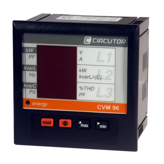
CONNECTIONS and SETUP sections and choose the most suitable operation mode for getting your desired data. The CVM 96 is an instrument which measures, calculates and displays all the main electrical parameters at any electrical network (balanced or not). The measuring is true RMS value, through three a.c. - Page 5 (Up to the 15 Available: x: Display and communications xx: Communications The CVM 96 delivers the visualization of above listed parameters by means of three 4-digit, led type, displays. Up to 3 parameters can be simultaneously read in the screen. --------------------------------------------------------------------------------------------- OTHER FEATURES Low-size (96 x 96 mm), panel-mounting analyzer.
-
Page 6: Installation And Start-Up
In this case contact a qualified service representative. 3.1.- Installation. Before powering the instrument for the first time, verify following points: Power supply: see rear part of your CVM 96 ∼ Standard supply : Single-phase 230 V (a.c.) - Page 7 ----- Supply network analyzer CVM 96 Ethernet -------- ----- Page No. 6 b.-Maximum voltage at the voltage measuring circuit: Standard : 300 V a.c. phase-to-neutral / 520 V a.c. phase-to-phase 45 to 65 Hz On request: 500 V a.c. phase-to-neutral / 866 V a.c. phase-to-phase 110 V a.c.
-
Page 8: Cvm 96 (Rs-485) Connection Terninal (See Lable On The Rear Part)
----- Supply network analyzer CVM 96 Ethernet -------- ----- Page No. 7 3.2.- CVM 96 (RS-485) Connection terninal (see lable on the rear part) Terminal description Upper connection terminal Relay RL1 output Relay RL2 output Relay common Current AL3 - S2 input... -
Page 9: Cvm 96 (Rs-232) Connection Terninal (See Lable On The Rear Part)
----- Supply network analyzer CVM 96 Ethernet -------- ----- Page No. 8 3.3.- CVM 96 (RS-232) Connection terninal (see lable on the rear part) RELAY ALARM RL2 COM Terminal description Upper connection terminal Relay RL1 output 10 11 12 13 14 15 16 17 18... -
Page 10: Connection Drawing For The Cvm 96
----- Supply network analyzer CVM 96 Ethernet -------- ----- Page No. 9 3.4.- Connection drawing for the CVM 96 a.- Three-phase network.- 4 wires (low voltage) : 10 11 12 13 14 15 16 17 18 Power Supply Power Supply (Model SDC) - Page 11 ----- Supply network analyzer CVM 96 Ethernet -------- ----- Page No. 10 b.-Three-phase network – 3 wires (low voltage): 10 11 12 13 14 15 16 17 18 Power Supply Power Supply (Model SDC) Terminal Description + V c.c. - V c.c.
- Page 12 ----- Supply network analyzer CVM 96 Ethernet -------- ----- Page No. 11 c.- Three-phase network - 3 wires (2 P.T. and 3 C.T.): 10 11 12 13 14 15 16 17 18 Power Supply Power Supply (Model SDC) Terminal Description + V c.c.
- Page 13 ----- Supply network analyzer CVM 96 Ethernet -------- ----- Page No. 12 d.- Three-phase network - 3 wires (2 P.T. and 2 C.T.): 10 11 12 13 14 15 16 17 18 Power Supply Power Supply (Model SDC) Terminal Description + V c.c.
-
Page 14: Operation Mode
(red colour). Every led will be on according to the parameter presently shown in screen. When the CVM 96 is powered up, the display shows " xxxx ", so informing about the program version and the SETUP. After some seconds, the analyzer is ready for operation and shows one of the available screens. - Page 15 ----- Supply network analyzer CVM 96 Ethernet -------- ----- Page No. 14 Pressing the "max" or "min" key, maximum or minimum values for the parameters being shown by display, respectively, appear in screen. This function is only valid while you keep pressing the "max" or "min" key. If you stop pressing the key the instantaneous values will appear again after 5 seconds.
-
Page 16: Setup Procedure
----- Page No. 15 5.- SETUP PROCEDURE The SETUP procedure of the CVM 96 is performed by means of several SETUP options. For accessing the SETUP menu the keys max & min must be simultaneously pressed once the instrument is at the main screen. -
Page 17: Phase-To-Phase Or Phase-To-Neutral Voltages
----- Supply network analyzer CVM 96 Ethernet -------- ----- Page No. 16 5.1.- Phase-to-Phase or Phase-to-Neutral voltages After the word "set" you will see on the three displays the voltages of the phases L1, L2, L3. Phase to Neutral Voltages:... -
Page 18: Voltage Transformation Ratio
----- Supply network analyzer CVM 96 Ethernet -------- ----- Page No. 17 5.3.- Voltage transformation ratio 5.3.1.- Voltage Transformer Primary On the screen we read the word "SET U P" followed by 5 digits. They allow us setting the primary of the voltage transformer. -
Page 19: Voltage Transformer Secondary
Press " " to pass to the next SETUP option. If the CVM 96 is directly connected to the mains (without voltage transformer) the values of primary and secondary must be the same, for instance 00001/001. 5.4.- Current Transformer Primary "SET A P"... -
Page 20: Setting Power Demand Utility Screens
----- Supply network analyzer CVM 96 Ethernet -------- ----- Page No. 19 NOTES: The secondary of the current transformers is not programmable. It is automatically set at 5 A (... / 5 A ac) The primary current value to be set is also limited by the following condition:... -
Page 21: Initial Screen Setting
Fixed screen (choice is switch just pressing ): choice among 10 available screen of the initial screen to be shown when the CVM 96 is powered (or when the CVM 96 is reset). b.- Rotary screens: all 10 screens are successively shown at intervals of 5 s. -
Page 22: Clearing Energy Counters
----- Supply network analyzer CVM 96 Ethernet -------- ----- Page No. 21 5.8.- Clearing energy counters On display we see "CLR ENER no" (Clear energy counters). - "max": To select "YES" or "no" - " ": To validate the choice and pass to the following SETUP option. -
Page 23: Thd Or D Setting
----- Supply network analyzer CVM 96 Ethernet -------- ----- Page No. 22 5.9.- THD or D setting DHAR dHAR Two modes for the harmonic distortion calculation can be selected: - d % : total value of the harmonic distortion referred to the fundamental value. -
Page 24: Additional Screens When Relay Outputs (2 Relays) Are Equipped
B.- ALARM conditions: the parameter to be controlled, the maximum value, the minimum value and the delay are user-definable for each relay output. ---------------------------------------------------------------------------------- On the CVM 96 screen following messages appear at this SETUP option: OUT 1 RELAY 1 CODE Parameter No. - Page 25 ----- Supply network analyzer CVM 96 Ethernet -------- ----- Page No. 24 Three-phase active power kW III Three-phase cos ϕ Cos ϕ Three-phase inductive power kvarL III Three-phase power factor PF III Three-phase capacitive kvarC III Frequency power Active energy...
- Page 26 ----- Supply network analyzer CVM 96 Ethernet -------- ----- Page No. 25 a.- If an ENERGY parameter is chosen: kW.h (31), kvarh.L (32) or kvarh.C(33) OUT 1 RELAY 1 PULS xxxx kW / pulse (1) Value of energy in kW : four digits with floating decimal point - SETUP procedure: - "max"...
- Page 27 MINIMUM value Delay for the conditions These screens are successively displayed by the CVM 96 once the parameter has been selected ( for the SETUP of each option proceed as in the Section a.-): b.1.- Programming the maximum value to be controlled:...
- Page 28 ----- Supply network analyzer CVM 96 Ethernet -------- ----- Page No. 27 b.2.- Programming the minimum value to be controlled: OUT 1 RELAY 1 AL LO 0.000 Minimum value b.3.- Programming the delay: OUT 1 RELAY 1 Delay in seconds 0.000...
- Page 29 ----- Supply network analyzer CVM 96 Ethernet -------- ----- Page No. 28 ALARM ACTIVATION: Alarms operation depend on the set values of MAXIMUM and MINIMUM. MIN + MAX + ====== max > min MIN + MAX + max < min ==============...
- Page 30 ----- Supply network analyzer CVM 96 Ethernet -------- ----- Page No. 29 The DELAY set value is applied either to the connection or the disconnection when the alarm conditions occur. User-definable units for the different parameters are: Parameter Format Example...
-
Page 31: Specifications
----- Supply network analyzer CVM 96 Ethernet -------- ----- Page No. 30 6.- SPECIFICATIONS Power supply : see specifications on the rear part of the CVM 96 - CVM 96 Single-phase 230 V a.c. Voltage tolerance: +10 % / -15 % Frequency: 50 ... - Page 32 ----- Supply network analyzer CVM 96 Ethernet -------- ----- Page No. 31 Mechanical Characteristics : - Connection : pluggable connection terminal - Case material Self-extinguishable, V0 plastic - Protection Assembled unit (frontal ) : IP 54 Un-assembled unit (side and rear covers) : IP 31...
-
Page 33: Safety Considerations
This instrument is factory-shipped at proper operation condition. 8.- MAINTENANCE The CVM 96 does not require any special maintenance. No adjustment, maintenance or repairing action should be done over the instrument open and powered and, should those actions are essential, high-qualified operators must perform them. -
Page 34: Cvm 96 Communications
CVM 96 COMMUNICATIONS ---- One or some CVM 96... can be connected to a P.C.. With this system we can get all the parameters in one central point of reading. The CVM 96..., has a serial RS-485 or RS-232 type output (according to the model). If we connect more than one device to the same communication line (RS-485), we have to assign to each of them a different code or direction (from 01 to 99), since the P.C. -
Page 35: Rs-485 Type Connection To A Rs-232 Type Input Of A Pc
----- Supply network analyzer CVM 96 Ethernet -------- ----- Page No. 34 10.2.- RS-485 TYPE CONNECTION TO A RS-232 TYPE INPUT OF A PC DB-9 RS-232 CONVERTER RS-232 / RS-485 RS-485 CVM 96 3 ( + ) CVM 96 4 ( - ) -
Page 36: Rs-232 Type Connection To A Rs-232 Type Input Of A Pc
----- Supply network analyzer CVM 96 Ethernet -------- ----- Page No. 35 10.3.- RS-232 TYPE CONNECTION TO A RS-232 TYPE INPUT OF A PC DB-9 RS-232 CVM 96 CVM-96 3 Tx CVM-96 CVM 96 4 Rx 5 GND... -
Page 37: Modbus © Protocol
----- Page No. 36 10.4.- MODBUS © protocol The CVM 96 analyzer can communicate by means of the MODBUS © protocol, as it is following described: When the CVM 96 communicates with MODBUS protocol, it uses the RTU mode (Remote Terminal Unit ). Each 8-bits byte in a message contains two 4-bits hexadecimal characters. - Page 38 ----- Supply network analyzer CVM 96 Ethernet -------- ----- Page No. 37 a.- Registers assigned to different parameters measured by the CVM 96: MODBUS REGISTERS PARAMETER Units (longs) HEXA-DECIMAL PRESENT MAXIMUM MINIMUM Value Value Value Phase voltage - V 1...
- Page 39 ----- Supply network analyzer CVM 96 Ethernet -------- ----- Page No. 38 MODBUS REGISTERS (longs) PARAMETER Units HEXA-DECIMAL PRESENT MAXIMUM MINIMUM Value Value Value Frequency (L1) - Hz Hz x 10 28-29 88-89 E8-E9 Line voltage L1-L2 - V12 V x 10...
- Page 40 ----- Supply network analyzer CVM 96 Ethernet -------- ----- Page No. 39 MODBUS REGISTERS PARAMETER Units (longs) HEXA-DECIMAL Fundamental 1F4-1F5 212-213 230-231 Harmonic 2 1F6-1F7 214-215 232-233 Harmonic 3 1F8-1F9 216-217 234-235 Harmonic 4 1FA-1FB 218-219 236-237 Harmonic 5 1FC-1FD 21A-21B...
- Page 41 ----- Supply network analyzer CVM 96 Ethernet -------- ----- Page No. 40 EXAMPLE INQUIRY 0A 04 00 00 00 0A 71 76 CVM 96 peripheral number, 10 in decimal Reading function 00 00 Initial address (first register) 00 0A Number of registers to be read...
- Page 42 = relay 1 ( 1 = ON ; 0 = OFF) bit b1 = relay 2 ( 1 = ON ; 0 = OFF) c.- Write of digital outputs This function is used to force the status of the CVM 96 digital outputs. Output No. Message...
-
Page 43: Appendix A: Second Setup Of The Cvm 96
APPENDIX A: Second SETUP of the CVM 96 A second SETUP menu is accessible in order to perform the configuration of the CVM 96 with other features different from factory-supplied ones. To access this menu proceed as follows: - Being the CVM 96 powered off, simultaneously press "... - Page 44 ----- Supply network analyzer CVM 96 Ethernet -------- ----- Page No. 43 If NO is chosen, pressing " " following options successively appear: - n PER Peripheral No. 001 to 255 - Baud 1 baud rate 1.200 – 2.400 – 4.800 – 9.600 – 19.200...
-
Page 45: Appendix C: Ethernet Communication
----- Supply network analyzer CVM 96 Ethernet -------- ----- Page No. 44 12.- APPENDIX C: Ethernet communication. Description of System Protocol and communications. The CVM96-Ethernet analyzer has been designed specially to communicate in Ethernet networks. Thanks to this communication system the wiring used in the RS485 network can be exceptionally optimized, improving this way the existing networks, and making very easy the installation procedure. - Page 46 ----- Supply network analyzer CVM 96 Ethernet -------- ----- Page No. 45 The device uses MODBUS RTU © communication protocol, and TCP or UDP transport protocol (according to the internal configuration). In case UDP transport protocol is used to connect the analyzer with the master...
- Page 47 ----- Supply network analyzer CVM 96 Ethernet -------- ----- Page No. 46 To assign an IP address to the device, we must know its “MAC ADDRESS”. This address appears in the label that is in the back side of the analyzer.
- Page 48 ----- Supply network analyzer CVM 96 Ethernet -------- ----- Page No. 47 UDP & TCP System Protocol UDP System Protocol If this communications protocol is selected, the master application must be able to generate UDP communications network, to naturally include Modbus communications network within the message.
- Page 49 ----- Supply network analyzer CVM 96 Ethernet -------- ----- Page No. 48 TCP System Protocol: The Com Port Redirector software must be installed when selecting the TCP communications protocol. This software allows the PC or master application to use the IP address of the CVM96-Ethernet as though it were a physical COM port on the computer.
- Page 50 ----- Supply network analyzer CVM 96 Ethernet -------- ----- Page No. 49 To avoid unwanted disconnections or disconnections from the amount of traffic, the communication tunnel reconnection options are enabled from the Port Settings option. The following is selected when the setting screen is opened: i.
Need help?
Do you have a question about the CVM 96 and is the answer not in the manual?
Questions and answers