Table of Contents
Advertisement
Quick Links
Advertisement
Table of Contents

Related Manuals for Circutor CVM-E3-MINI


Summary of Contents for Circutor CVM-E3-MINI
- Page 1 Power analyzer CVM-E3-MINI INSTRUCTION MANUAL (M170B01-03-22B)
- Page 2 CVM-E3-MINI Instruction Manual...
-
Page 3: Safety Precautions
CIRCUTOR S�A�U� reserves the right to make modifications to the device or the unit specifications set out in this instruction manual without prior notice. CIRCUTOR S�A�U� on its web site, supplies its customers with the latest versions of the device specifi- cations and the most updated manuals. -
Page 4: Table Of Contents
3�5�3�- MODELS CVM-E3-MINI-ITF-WiEth AND CVM-E3-MINI-MC-WiEth ��������������������������������������������������������������� 15 3�5�4�- MODEL CVM-E3-MINI-FLEX-WiEth ���������������������������������������������������������������������������������������������������������������� 15 3�6�- CONNECTION DIAGRAM ����������������������������������������������������������������������������������������������������������������������������������������� 16 3�6�1�- MEASURING THREE-PHASE NETWORKS WITH A 4-WIRE CONNECTION: CVM-E3-MINI-ITF AND CVM-E3- MINI-ITF-WiEth ����������������������������������������������������������������������������������������������������������������������������������������������������������� 16 3�6�2�- MEASURING THREE-PHASE NETWORKS WITH A 4-WIRE CONNECTION: CVM-E3-MINI-MC AND CVM-E3- MINI-MC-WiEth�... - Page 5 5�1�5�- DETECTION OF INCORRECT CONNECTION AND INCORRECT DIRECTION OF ROTATION ������������������������������44 5�2�- e PROFILE �������������������������������������������������������������������������������������������������������������������������������������������������������������45 5�3�- DEVICE INFORMATION SCREENS ���������������������������������������������������������������������������������������������������������������������������49 5�4�- DIGITAL INPUT AND OUTPUT STATUS SCREEN (Models CVM-E3-MINI-xxx) �������������������������������������������������������49 5�5�- ETHERNET - Wi-Fi - Bluetooth COMMUNICATIONS SCREENS ���������������������������������������������������������������������������� 50 ®...
- Page 6 CVM-E3-MINI 6�23�- LOCKING THE PROGRAMMING ����������������������������������������������������������������������������������������������������������������������������84 6�23�1�- PASSWORD ���������������������������������������������������������������������������������������������������������������������������������������������������85 7�- CVM-E3-MINI-XXX : RS-485 COMMUNICATIONS ���������������������������������������������������������������������������������������������������������86 7�1�- CONNECTIONS ��������������������������������������������������������������������������������������������������������������������������������������������������������86 7�2�- MODBUS PROTOCOL ����������������������������������������������������������������������������������������������������������������������������������������������87 7�2�1�- READING EXAMPLE : Funtion 0x04� ��������������������������������������������������������������������������������������������������������������87 7�2�2�- WRITING EXAMPLE : Funtion 0x05� ��������������������������������������������������������������������������������������������������������������87 7�3�- MODBUS COMMANDS ������������������������������������������������������������������������������������������������������������������������������������������ 88 7�3�1�...
-
Page 7: Revision Log
CVM-E3-MINI REVISION LOG Table 1: Revision log� Date Revision Description 12/17 M170B01-03-17A Initial Version Changes in the following sections: 02/18 M170B01-03-18A 3.3. - 6.17.- 10. Changes in the following sections: 04/18 M170B01-03-18B 3.2.- 3.5. - 5.1.5 - 7.3.6. Changes in the following sections:... -
Page 8: 1�- Verification Upon Reception
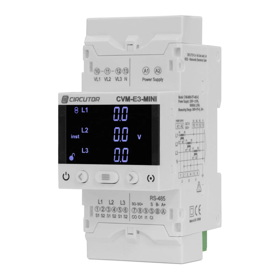
CIRCUTOR's after-sales service. 2.- PRODUCT DESCRIPTION The CVM-E3-MINI device measures, calculates and displays the main electrical parameters of the following networks: single-phase, two-phase, with and without neutral, balanced three-phase, with ARON measurements or unbalanced. The measurement will be taken in RMS with the three AC voltage inputs and three current inputs. - Page 9 CVM-E3-MINI The device features: - 3 keys that allow you to browse between the various screens and program the device. - 2 indicator LEDs: CPU and ALARM. - LCD display, displays all parameters. Note: Devices with software version v1.xx cannot be upgraded to version v2�xx and vice versa.
-
Page 10: 3�- Device Installation
The CVM-E3-MINI device must be installed by authorised and qualified staff. The power supply plug must be disconnected and measuring systems switched off before handling, al- tering the connections or replacing the device. -
Page 11: 3�2�- Installation
3�3�- PANEL MOUNTING ACCESSORY (72 x 72 mm) Note: The 72 x 72 mm panel mounting accessory is an accessory that is sold separately. CIRCUTOR has a panel mounting accessory of the CVM-E3-MINI equipment so that it can be installed on 72 x 72 mm panels. - Page 12 CVM-E3-MINI Figure 2: Installation of the panel mounting accessory� Table 4: Technical features� Technical features Protection degree IP40 Enclosure Self-extinguishing V0 plastic 68 mm 68 mm Figure 3: Panel cut-out� Instruction Manual...
-
Page 13: 3�4�- Cvm-E3-Mini-Flex: Rogowski Sensors
The flexibility of the sensor allows it to measure an alternating current irrespective of the position of the conductor. CIRCUTOR has 1 Rogowski sensor model that can be used with the CVM-E3-MINI-FLEX: FLEX-MAG� shows the connection of the sensors and the maximum position error. -
Page 14: 3�5�- Device Terminals
CVM-E3-MINI 3�5�- DEVICE TERMINALS 3�5�1�- MODELS CVM-E3-MINI-ITF AND CVM-E3-MINI-MC Figure 4: CVM-E3-MINI-ITF / -MC / -FLEX terminals: Up - Down Table 7: Device terminals: CVM-E3-MINI-ITF and CVM-E3-MINI-MC Device terminals A1: ~ +, Power supply 4: S2, current input L2 A2: ~ -, Power supply... -
Page 15: 3�5�3�- Models Cvm-E3-Mini-Itf-Wieth And Cvm-E3-Mini-Mc-Wieth
CVM-E3-MINI 3�5�3�- MODELS CVM-E3-MINI-ITF-WiEth AND CVM-E3-MINI-MC-WiEth Ethernet Figure 5: CVM-E3-MINI-ITF/-MC/-FLEX-WiEth terminals: Up - Down� Table 9: Device terminals: CVM-E3-MINI-ITF-WiEth and CVM-E3-MINI-MC-WiEth Device terminals 2: S2, current input L1 A1: ~ +, Power supply A2: ~ -, Power supply 3: S1, current input L2... -
Page 16: 3�6�- Connection Diagram
P2 S1 P2 S1 CARGA / LOAD Figure 6: Three-Phase measuring with a 4-wire connection: CVM-E3-MINI-ITF and CVM-E3-MINI-ITF-WiEth� To guarantee the insulation of the device and its category, it is necessary to earth the S2 terminals of the transformers. Instruction Manual... -
Page 17: Mini-Mc-Wieth
Grey/Pink Green/White Red/Blue Brown/Green CARGA / LOAD Figure 7: Three-Phase measuring with a 4-wire connection:CVM-E3-MINI-MC and CVM-E3-MINI-MC-WiEth� Note: Do not connect MC current transformers to ground. The MC transformer secondary value is set to 0.250 A (fixed value). Instruction Manual... -
Page 18: Cvm-E3-Mini-Flex-Wieth
3�6�3�- MEASURING THREE-PHASE NETWORKS WITH A 4-WIRE CONNECTION: CVM-E3-MINI-FLEX AND CVM-E3-MINI-FLEX-WiEth Measurement system: 4-3Ph Alimentación Auxiliar Power Supply SHLD SHLD CARGA / LOAD Figure 8: Three-Phase measuring with a 4-wire connection: CVM-E3-MINI-FLEX and CVM-E3-MINI-FLEX-WiEth� It is mandatory connect the SHLD terminal of the probe. Instruction Manual... - Page 19 P2 S1 P2 S1 CARGA / LOAD Figure 9: Three-Phase measuring with a 3-wire connection: CVM-E3-MINI-ITF and CVM-E3-MINI-ITF-WiEth� To guarantee the insulation of the device and its category, it is necessary to earth the S2 terminals of the transformers. Instruction Manual...
-
Page 20: Cvm-E3-Mini-Mc-Wieth
Green/White Red/Blue Brown/Green CARGA / LOAD Figure 10: Three-Phase measuring with a 3-wire connection: CVM-E3-MINI-MC and CVM-E3-MINI-MC-WiEth� Note: Do not connect MC current transformers to ground. The MC transformer secondary value is set to 0.250 A (fixed value). Instruction Manual... -
Page 21: Cvm-E3-Mini-Flex-Wieth
3�6�6�- MEASURING THREE-PHASE NETWORKS WITH A 3-WIRE CONNECTION: CVM-E3-MINI-FLEX AND CVM-E3-MINI-FLEX-WiEth Measurement system: 3-3Ph Alimentación Auxiliar Power Supply SHLD SHLD CARGA / LOAD Figure 11: Three-Phase measuring with a 3-wire connection: CVM-E3-MINI-FLEX and CVM-E3-MINI-FLEX-WiEth� It is mandatory connect the SHLD terminal of the probe. Instruction Manual... -
Page 22: 3�6�7�- Measuring Three-Phase Networks With A 3-Wire Connection And Transformers With An Aron Connection: Cvm-E3-Mini-Itf And Cvm-E3-Mini-Itf-Wieth
Alimentación Auxiliar Power Supply CARGA / LOAD Figure 12: Three-Phase measuring with a 3-wire connection and transformers with an ARON connection: CVM-E3-MINI-ITF and CVM-E3-MINI-ITF-WiEth� To guarantee the insulation of the device and its category, it is necessary to earth the S2 terminals of the transformers. -
Page 23: 3�6�8�- Measuring Three-Phase Networks With A 3-Wire Connection And Transformers With An Aron Connection: Cvm-E3-Mini-Mc And Cvm-E3-Mini-Mc-Wieth
Alimentación Auxiliar Power Supply CARGA / LOAD Figure 13: Three-Phase measuring with a 3-wire connection and transformers with an ARON connection: CVM-E3-MINI-MC and CVM-E3-MINI-MC-WiEth� Note: Do not connect MC current transformers to ground. The MC transformer secondary value is set to 0.250 A (fixed value). -
Page 24: Cvm-E3-Mini-Itf-Wieth
Power Supply P2 S1 CARGA / LOAD Figure 14: Measuring Two-Phase Networks with a 3-wire connection: CVM-E3-MINI-ITF and CVM-E3-MINI-ITF-WiEth� To guarantee the insulation of the device and its category, it is necessary to earth the S2 terminals of the transformers. -
Page 25: Mini-Mc-Wieth
Power Supply P2 S1 CARGA / LOAD Figure 15: Measuring Two-Phase Networks with a 3-wire connection: CVM-E3-MINI-MC and CVM-E3-MINI-MC-WiEth� Note: Do not connect MC current transformers to ground. The MC transformer secondary value is set to 0.250 A (fixed value). -
Page 26: Cvm-E3-Mini-Flex-Wieth
3�6�11�- MEASURING TWO-PHASE NETWORKS WITH A 3-WIRE CONNECTION: CVM-E3-MINI-FLEX AND CVM-E3-MINI-FLEX-WiEth Measurement system: 3-2Ph Alimentación Auxiliar Power Supply SHLD SHLD CARGA / LOAD Figure 16: Measuring Two-Phase Networks with a 3-wire connection: CVM-E3-MINI-FLEX and CVM-E3-MINI-FLEX-WiEth� It is mandatory connect the SHLD terminal of the probe. Instruction Manual... -
Page 27: 3�6�12�- Measuring Single-Phase Networks, Phase To Phase, With A 2-Wire Connection: Cvm-E3-Mini-Itf And Cvm-E3-Mini-Itf-Wieth
Alimentación Auxiliar Power Supply CARGA / LOAD Figure 17: Measuring Single-Phase Networks, phase to phase, with a 2-wire connection: CVM-E3-MINI-ITF and CVM-E3-MINI-ITF- WiEth� To guarantee the insulation of the device and its category, it is neces- sary to earth the S2 terminals of the transformers. -
Page 28: 3�6�13�- Measuring Single-Phase Networks, Phase To Phase, With A 2-Wire Connection: Cvm-E3-Mini-Mc And Cvm-E3-Mini-Mc-Wieth
Alimentación Auxiliar Power Supply CARGA / LOAD Figure 18: Measuring Single-Phase Networks, phase to phase, with a 2-wire connection: CVM-E3-MINI-MC and CVM-E3-MINI-MC- WiEth� Note: Do not connect MC current transformers to ground. The MC transformer secondary value is set to 0.250 A (fixed value). -
Page 29: Cvm-E3-Mini-Flex And Cvm-E3-Mini-Flex-Wieth
Measurement system: 2-2Ph Alimentación Auxiliar Power Supply SHLD SHLD CARGA / LOAD Figure 19: Measuring Single-Phase Networks, phase to phase, with a 2-wire connection: CVM-E3-MINI-FLEX and CVM-E3-MINI- FLEX-WiEth� It is mandatory connect the SHLD terminal of the probe. Instruction Manual... -
Page 30: 3�6�15�- Measuring Single-Phase Networks, Phase To Neutral, With A 2-Wire Connection: Cvm-E3-Mini-Itf And Cvm-E3-Mini-Itf-Wieth
Alimentación Auxiliar Power Supply CARGA / LOAD Figure 20: Measuring Single-Phase Networks, phase to neutral, with a 2-wire connection: CVM-E3-MINI-ITF and CVM-E3-MINI- ITF-WiEth� To guarantee the insulation of the device and its category, it is necessary to earth the S2 terminals of the transformers. -
Page 31: 3�6�16�- Measuring Single-Phase Networks, Phase To Neutral, With A 2-Wire Connection: Cvm-E3-Mini-Mc And Cvm-E3-Mini-Mc-Wieth
Alimentación Auxiliar Power Supply CARGA / LOAD Figure 21: Measuring Single-Phase Networks, phase to neutral, with a 2-wire connection:CVM-E3-MINI-MC and CVM-E3-MINI-MC- WiEth� Note: Do not connect MC current transformers to ground. The MC transformer secondary value is set to 0.250 A (fixed value). -
Page 32: 3�6�17�- Measuring Single-Phase Networks, Phase To Neutral, With A 2-Wire Connection: Cvm-E3-Mini-Flex And Cvm-E3-Mini-Flex-Wieth
TION: CVM-E3-MINI-FLEX AND CVM-E3-MINI-FLEX-WiEth Measurement system: 2-1Ph Alimentación Auxiliar Power Supply SHLD SHLD CARGA / LOAD Figure 22: Measuring Single-Phase Networks, phase to neutral, with a 2-wire connection:CVM-E3-MINI-FLEX and CVM-E3-MINI- FLEX-WiEth� It is mandatory connect the SHLD terminal of the probe. Instruction Manual... -
Page 33: 4�- Operation
CVM-E3-MINI 4.- OPERATION The CVM-E3-MINI is a four-quadrant power analyzer (consumption and generation). The device can operate according to three different measurement conventions: CIRCUTOR measurement convention. IEC measurement convention. IEEE measurement convention. The measurement convention is configured in the setup menu, see “6.7. -
Page 34: 4�1�- Measuring Parameters
< P > 0 Q < 0 > Figure 25: IEEE measurement convention� 4�1�- MEASURING PARAMETERS The device displays the electrical parameters shown in Table 11 Table 11: Measuring parameters of the CVM-E3-MINI Phases Total Maxim� Minim� Parameter Units L1-L2-L3... - Page 35 CVM-E3-MINI Table 11 (Continuation): Measuring parameters of the CVM-E3-MINI� Phases Total Maxim� Minim� Parameter Units L1-L2-L3 value value Harmonic Breakdown - Voltage harm V (up to the 31st order harmonic) Harmonic Breakdown - Current harm V (up to the 31st order harmonic)
-
Page 36: 4�2�- Keyboard Functions
CVM-E3-MINI 4�2�- KEYBOARD FUNCTIONS The CVM-E3-MINI has 3 keys that allow you to browse between the various screens and program the device. Key functions on measuring screens ( Table 12 Table 12: Key functions on measuring screens� Short keystroke Long keystroke (2 s) -
Page 37: 4�3�- Display
Figure 26 Data area States area Figure 26: CVM-E3-MINI Display areas The data area displays the values measured or calculated by the device. The device states area shows the different states, profiles and information about the unit Table 16 Table 16: Icons in the display�... -
Page 38: 4�4�- Led Indicators
ALARM / ENERGY PULSES Figure 27: LED Indicators of the CVM-E3-MINI� 4�5�- DIGITAL INPUT (Models CVM-E3-MINI-xxx) The CVM-E3-MINI-xxx has one digital input (terminals S and 9 on ) that can be programmed Figure 4 to operate as a logic input, tariff selection or pulse counter. -
Page 39: 4�6�- Digital Output (Models Cvm-E3-Mini-Xxx)
IN1, Input 1 Tariff Logic input Tariff selection Note: In the CVM-E3-MINI-xxx-WiEth models, the tariff is selected in the settings menu. 4�6�- DIGITAL OUTPUT (Models CVM-E3-MINI-xxx) The device has one digital output, optoisolated NPN transistors (terminals 8 and 7 on ), fully... -
Page 40: 5�- Display
CVM-E3-MINI 5.- DISPLAY The CVM-E3-MINI has 2 operation profiles. The display screens will be opened for the corresponding profile: Analyzer profile, analyzer, Electrical energy efficiency profile, e By default, the device displays the electrical energy efficiency profile, e... - Page 41 CVM-E3-MINI Table 18 (Continuation): Analyzer profile screens� Screen Parameters (units) Current L1 (A) Current L2 (A) Current L3 (A) Active Power L1 (M/kW) Active Power L2 (M/kW) Active Power L3 (M/kW) Apparent Power L1 (M/kVA) Apparent Power L2 (M/kVA) Apparent Power L3 (M/kVA)
- Page 42 CVM-E3-MINI Table 18 (Continuation): Analyzer profile screens� Screen Parameters (units) Active Power III (M/kW) Apparent Power III (M/kVA) Capacitive Reactive Power III (M/kvar Cos φ L1 (cos φ) Cos φ L2 (cos φ) Cos φ L3 (cos φ) Power factor L1 (PF)
-
Page 43: 5�1�1�- Maximum Values
CVM-E3-MINI 5�1�1�- MAXIMUM VALUES To see the maximum values of the screen being displayed, press the key for 2 seconds. These are displayed for 10 seconds. Press the keys to display all other maximum values. The max symbol is shown on the display. -
Page 44: 5�1�5�- Detection Of Incorrect Connection And Incorrect Direction Of Rotation
CVM-E3-MINI required to measure the voltage harmonics and of at least 200 mA to measure the current harmonics. If the levels are lower, the unit will not calculate them and will display a value of 0. The harmonics display screens can be displayed by pressing the key shown after the last profile screen. -
Page 45: Profile
CVM-E3-MINI 5�2�- e PROFILE The installation’s consumed and generated energy are displayed on the e profile of the device. The installation status is also displayed: Installation is consuming energy. Installation is generating energy. Long press (3 sec.) the keys to jump from the generated values to the consumed values displayed. - Page 46 CVM-E3-MINI Table 19 (Continuation): Screens of the e profile� Screen Parameters (units) Total Cost (cost) Total CO Emissions (kgCO Total No. of hours (hours) Three-phase Active Energy Tariff 1 (kWh) Three-phase Apparent Energy Tariff 1 (kVAh) Three-phase Inductive Reactive Energy Tariff 1...
- Page 47 CVM-E3-MINI Table 19 (Continuation): Screens of the e profile� Screen Parameters (units) Three-phase Capacitive Reactive Energy Tariff 1 (kvar Cost Tariff 1 (cost) Emissions Tariff 1 (kgCO No. of hours Tariff 1 (hours) Three-phase Active Energy Tariff 2 (kWh) Three-phase Apparent Energy Tariff 2...
- Page 48 CVM-E3-MINI Table 19 (Continuation): Screens of the e profile� Screen Parameters (units) Three-phase Inductive Reactive Energy Tariff 2 (kvar Three-phase Capacitive Reactive Energy Tariff 2 (kvar Cost Tariff 2 (cost) Emissions Tariff 2 (kgCO No. of hours Tariff 2 (hours) Total = Tariff 1 + Tariff 2.
-
Page 49: 5�3�- Device Information Screens
( Figure 29 Figure 29: Device information screens� 5�4�- DIGITAL INPUT AND OUTPUT STATUS SCREEN (Models CVM-E3-MINI-xxx) Press the keys at the same time on any display screen to show the status of the device’s... -
Page 50: 5�5�- Ethernet - Wi-Fi - Bluetooth ® Communications Screens
CVM-E3-MINI 5�5�- ETHERNET - Wi-Fi - Bluetooth COMMUNICATIONS SCREENS ® (Models CVM-E3-MINI-xxx-WiEth) Note: shows the full settings tree structure. “ANNEX A - CONFIGURATION MENUS” Press the keys simultaneously from any display screen to show the settings and display screens for Ethernet, Wi-Fi and Bluetooth communications. -
Page 51: 5�5�3� Ethernet Communications: Ip Mask
CVM-E3-MINI key for 3 seconds to enter the edit mode. The prog icon will flash on the left of the Press the screen. Press the key to modify the value of the flashing digit. When the desired value is shown on the screen, use the... -
Page 52: 5�5�4� Ethernet Communications: Gateway
CVM-E3-MINI 5�5�4� ETHERNET COMMUNICATIONS: GATEWAY You can set up (DHCP disabled) or view the gateway for Ethernet communications on this screen. Press the key to display the value. key for 3 seconds to enter the edit mode. The prog icon will flash on the left of the Press the screen. -
Page 53: 5�5�6� Wi-Fi Communications: Ip Address
CVM-E3-MINI 5�5�6� WI-FI COMMUNICATIONS: IP ADDRESS This screen shows the IP address for Wi-Fi communications. Press the key to display the value. To access the following communications screen press the key Note: Wi-Fi communications work only in DHCP mode. 5�5�7� WI-FI COMMUNICATIONS: MAC ADDRESS This screen shows the MAC address for Wi-Fi communications. -
Page 54: 5�5�9� Bluetooth
CVM-E3-MINI 5�5�9� Bluetooth COMMUNICATIONS: NAME ® This screen shows the device name for Bluetooth communications. ® Press the key to display the value. Press the keys simultaneously to exit the Ethernet, Wi-Fi and Bluetooth communications ® screens. Instruction Manual... -
Page 55: 6�- Configuration
CVM-E3-MINI 6.- CONFIGURATION To enter the configuration menu press the key for 3 seconds. If the icon appears on the configuration screen, the configuration parameters can be edited. If the icon appears, the configuration of the unit will be locked with a password (“... -
Page 56: 6�1�- Primary Voltage
CVM-E3-MINI 6�1�- PRIMARY VOLTAGE On this screen the voltage transformer primary is programmed. key for 3 seconds to enter the edit mode. The prog icon will flash on the left of the Press the screen. Press the key to modify the value of the flashing digit. -
Page 57: 6�3�- Primary Current
Press key to access the next programming step. 6�3�- PRIMARY CURRENT Note: Display visible on models: CVM-E3-MINI-ITF, CVM-E3-MINI-ITF-WiEth, CVM-E3-MINI-MC and CVM-E3-MINI-MC-WiEth. The current transformer primary is programmed on this screen. key for 3 seconds to enter the edit mode. The prog icon will flash on the left of the Press the screen. -
Page 58: 6�4�- Secondary Current (Model Cvm-E3-Mini-Itf)
6�4�- SECONDARY CURRENT (MODEL CVM-E3-MINI-ITF) Note: Display visible on models: CVM-E3-MINI-ITF and CVM-E3-MINI-ITF-WiEth. On this screen the current transformer secondary is selected. key for 3 seconds to enter the edit mode. The prog icon will flash on the left of the Press the screen. -
Page 59: 6�5�- Flex Sensor
CVM-E3-MINI 6�5�- FLEX SENSOR Note: Display visible on models: CVM-E3-MINI-FLEX and CVM-E3-MINI-FLEX-WiEth. On this screen, you can select the Rogowski flexible sensor, which will be used to measure the current. key for 3 seconds to enter the edit mode. The prog icon will flash on the left of the Press the screen. -
Page 60: 6�7�- Measurement Convention
The key is used to browse the different options. Configuration values Table 27: Configuration values: Measurement convention� Measurement convention Circutor measurement convention. Possible values IEC measurement convention IEEE IEEE measurement convention key for 3 seconds; the prog icon will stop flashing. -
Page 61: 6�9�- Maximum Demand Integration Period
Single-phase network measurement, phase to neutral, with a 2-1Ph 2-wire connection. Option not available for the models: CVM-E3-MINI-FLEX and CVM-E3-MINI-FLEX-WiEth. To validate the value, press the key for 3 seconds; the prog icon will stop flashing. Press key to access the next programming step. -
Page 62: 6�10�- Deleting Maximum Demand
CVM-E3-MINI Configuration values Table 29: Configuration values: Integration period� Integration period Minimum value 0 minutes Maximum value 60 minutes Note: Programming the value 0 disables the calculation of the maximum demand. Press key to access the next programming step. -
Page 63: 6�11�- Deleting Maximum And Minimum Values
CVM-E3-MINI 6�11�- DELETING MAXIMUM AND MINIMUM VALUES On this screen you select whether or not to delete the maximum and minimum values key for 3 seconds to enter the edit mode. The prog icon will flash on the left of the Press the screen. -
Page 64: 6�13�- Enable Harmonics Display Screen
CVM-E3-MINI Configuration values Table 32: Configuration values: Deleting Energy� Deleting Energy Possible values key for 3 seconds; the prog icon will stop flashing. To validate the value, press the Select Yes to force the device to automatically delete all values; the No option will be displayed again on the screen. -
Page 65: 6�15�- Kgc0 2 Carbon Emission Ratio Of Generated Energy
CVM-E3-MINI This screen is used to programme the carbon emissions ratio for consumed energy, using the 2 tariffs configured for the device: T1 on the top line and T2 on the bottom line. key for 3 seconds to enter the edit mode. The prog icon will flash on the left of the Press the screen. -
Page 66: 6�16�- Cost Ratio Of Consumed Energy
CVM-E3-MINI key for 3 seconds to enter the edit mode. The prog icon will flash on the left of the Press the screen. Press the key to modify the value of the flashing digit. When the desired value is shown on the screen, use the keys to move the edit cursor. -
Page 67: 6�17�- Cost Ratio Of Generated Energy
CVM-E3-MINI Configuration values Table 36: Configuration values: Cost ratio (Consumed energy)� Cost ratio (Consumed energy) Minimum value 1.9999 Maximum value Press key to access the next programming step. 6�17�- COST RATIO OF GENERATED ENERGY This screen is used to programme the cost per kWh of electricity for generated energy, using the 2 tariffs configured for the device: T1 on the top line and T2 on the bottom line. -
Page 68: 6�18�- Programming Alarm : Digital Output T1
CVM-E3-MINI 6�18�- PROGRAMMING ALARM : DIGITAL OUTPUT T1 The values corresponding to digital output T1 are programmed in this step. The code of the variable is selected on this screen, according to , which Table 38 Table 39 Table 40 will control digital output T1. - Page 69 CVM-E3-MINI Table 38 (Continuation): Parameter codes used to program the digital output (Table 1)� Parameter Phase Code Phase Code Phase Code Phase Code Inductive Power Maximum Demand Capacitive Power Maximum Demand In addition, there are some parameters ( ) that refer to the three phases at the same time (OR Table 14 function).
-
Page 70: 6�18�1� Maximum Value
CVM-E3-MINI 6�18�1� MAXIMUM VALUE This screen is used to programme the maximum value, i.e., the value above which the alarm will be activated. Press the key for 3 seconds to enter the edit mode. The prog icon will flash on the left of the screen. -
Page 71: 6�18�3� Connection Time Delay
CVM-E3-MINI Note: Pay special attention when programming the Generation Power (displayed with negative values). Example: If you wish to enter a generation power alarm with limits between 2 kW and 1 kW, program the following as the maximum value : - 1 kW and the following as the minimum value : - 2 kW. -
Page 72: 6�18�5� Latch
CVM-E3-MINI key for 3 seconds to enter the edit mode. The prog icon will flash on the left of the Press the screen. Press the key to modify the value of the flashing digit. When the desired value is shown on the screen, use the keys to move the edit cursor. -
Page 73: 6�18�6� Latch Time
CVM-E3-MINI 6�18�6� LATCH TIME Note: Screen visible if the latch has been enabled, see “6.18.5. LATCH”. This screen is used to program the latch time, meaning the time in seconds when the alarm will be latched. After this time, if the alarm condition has cleared, the disconnection delay is activated Press the key for 3 seconds to enter the edit mode. -
Page 74: 6�18�8� Contact Status
CVM-E3-MINI To validate the value, press the key for 3 seconds; the prog icon will stop flashing. Configuration values Table 45: Configuration values: Disconnection time delay� Disconnection time delay Minimum value 0 s. Maximum value 999 s. Press key to access the next programming step. -
Page 75: 6�18�10� Pulse Width
CVM-E3-MINI key for 3 seconds to enter the edit mode. The prog icon will flash on the left of the Press the screen. Press the key to modify the value of the flashing digit. When the desired value is shown on the screen, use the keys to move the edit cursor. -
Page 76: 6�19�- Operating Mode Of Digital Input (Models Cvm-E3-Mini-Xxx)
Press key to access the next programming step. 6�19�- OPERATING MODE OF DIGITAL INPUT (Models CVM-E3-MINI-xxx) The function of digital input 1 is selected on this screen. Press the key for 3 seconds to enter the edit mode. -
Page 77: 6�20�- Tariff Selection (Models Cvm-E3-Mini-Xxx-Wieth)
CVM-E3-MINI 6�20�- TARIFF SELECTION (Models CVM-E3-MINI-xxx-WiEth) You can select the operating tariff on this screen. key for 3 seconds to enter the edit mode. The prog icon will flash on the left of the Press the screen. Press key to browse the two options. -
Page 78: 6�22�- Rs-485 Communications (Models Cvm-E3-Mini-Xxx)
Press key to access the next programming step. 6�22�- RS-485 COMMUNICATIONS (Models CVM-E3-MINI-xxx) The RS-485 communications protocol is selected on this screen. key for 3 seconds to enter the edit mode. The prog icon will flash on the left of the Press the screen. -
Page 79: 6�22�1�- Modbus Protocol: Baud Rate
CVM-E3-MINI If the BACnet protocol has been selected, the next setup screen will be shown in section “6.22.6.- BACnet PROTOCOL: BAUD RATE”. 6�22�1�- MODBUS PROTOCOL: BAUD RATE The baud rate of modbus communications is programmed on this screen. Press the key for 3 seconds to enter the edit mode. -
Page 80: 6�22�3�- Modbus Protocol: Parity
CVM-E3-MINI Configuration values Table 54: Configuration values: Modbus protocol: Peripheral number Peripheral number Minimum value Maximum value To validate the value, press the key for 3 seconds; the prog icon will stop flashing. If the value entered by the user is out of the range of programming values, the programmed value will be deleted and the system will restore it to the last saved value. -
Page 81: 6�22�4�- Modbus Protocol: Data Bits
CVM-E3-MINI 6�22�4�- MODBUS PROTOCOL: DATA BITS The number of data bits of Modbus communications are programmed on this screen. Press the key for 3 seconds to enter the edit mode. The prog icon will flash on the left of the screen. -
Page 82: 6�22�6�- Bacnet Protocol : Baud Rate
CVM-E3-MINI 6�22�6�- BACnet PROTOCOL : BAUD RATE The baud rate of BACnet communications is programmed on this screen. Press the key for 3 seconds to enter the edit mode. The prog icon will flash on the left of the screen. -
Page 83: 6�22�8�- Bacnet Protocol : Mac Address
CVM-E3-MINI key for 3 seconds; the prog icon will stop flashing. To validate the value, press the If the value entered by the user is out of the range of programming values, the programmed value will be deleted and the system will restore it to the last saved value. -
Page 84: 6�23�- Locking The Programming
CVM-E3-MINI 6�23�- LOCKING THE PROGRAMMING This screen is for protecting the data configured in the programming menu. Press the key for 3 seconds to enter the edit mode. The screen shown in will be Figure 32 displayed, in which the user must enter the locking password. -
Page 85: 6�23�1�- Password
CVM-E3-MINI for 3 seconds and the prog icon will disappear from the display. To validate the data, press Press the key to enter the password for locking and unlocking the programming: 6�23�1�- PASSWORD On this screen you enter the password for locking and unlocking the programming. -
Page 86: 7�- Cvm-E3-Mini-Xxx : Rs-485 Communications
CVM-E3-MINI and the master device of 1200 metres. A maximum of 32 CVM-E3-MINI devices can be connected to this bus. Use an intelligent RS-232 to RS-485 network protocol converter to establish the communications with the master device. -
Page 87: 7�2�- Modbus Protocol
CVM-E3-MINI 7�2�- MODBUS PROTOCOL In the Modbus protocol, the CVM-E3-MINI device uses the RTU (Remote Terminal Unit) mode. The Modbus functions implemented in the device are as follows: Function 0x03 and 0x04. Reading integer registers. Function 0x05. Writing a relay. -
Page 88: 7�3�- Modbus Commands
Map 2, uses the addresses of the CVM-C10 device (adding 0x1000 to all addresses). Except for 3 parameters, the CVM-C10 and the CVM-E3-MINI use the same parameters. Map 2 should be used if a Modbus map is going to be implemented from scratch. However, if the map is already being used in another device, use Map 1 for CVM-MINI and Map 2 for CVM-C10. - Page 89 CVM-E3-MINI Table 62 (Continuation): Modbus memory Map 1: Measurement variables Mapa 1 Parameter Symbol Instantaneous Maximum Minimum Units L3 Current 16-17 76-77 D6-D7 L3 Active Power kW 3 18-19 78-79 D8-D9 L3 Reactive Power kvar 3 1A-1B 7A-7B DA-DB L3 Inductive Power...
- Page 90 CVM-E3-MINI Tabla 63 (Continuation): Modbus memory Map 2: Measurement variables Map 2 Parameter Symbol Instantaneous Maximum Minimum Units L1 Power Factor PF 1 100C-100D 1112-1113 1170-1171 x 100 Cos φ L1 Cos φ 1 100E-100F 1114-1115 1172-1173 x 100 L2 Phase voltage...
-
Page 91: 7�3�2� Energy Variables
CVM-E3-MINI 7�3�2� ENERGY VARIABLES For these variables is implemented the Function 0x03 and 0x04� Table 64: Modbus memory Map 1 (Instantaneous energy variables) Map 1 Parameter Symbol instantaneous Units Active energy III kWh III 3C-3D Inductive reactive energy III kvarhL III... - Page 92 CVM-E3-MINI Table 66: Modbus memory Map 2: Energy variables Map 2 Parameter Symbol Tariff 1 Tariff 2 Total Units Consumed active energy III (kWh) kWh III 105E-105F 1088-1089 10DC-10DD Consumed active energy III (Wh) kWh III 1060-1061 108A-108B 10DE-10DF Consumed inductive reactive energy III...
-
Page 93: 7�3�3� Voltage And Current Harmonics
CVM-E3-MINI Table 67 (Continuation): Modbus memory Map 1 and Map 2 (energy variables per phase) Map 1 and Map 2 Parameter Symbol Units Consumed inductive reactive energy T2 kvarhL 1424-1425 1484-1485 14E4-14E5 kvarh (kvarhL) Consumed inductive reactive energy T2(var- kvarhL... - Page 94 CVM-E3-MINI Table 68 (Continuation): Modbus memory Map 1: Voltage Harmonics Map 1 Parameter Voltage L1 Voltage L2 Voltage L3 Units 17th Order harmonic 30A-30B 32A-32B 34A-34B % x 10 18th Order harmonic 30C-30D 32C-32D 34C-34D % x 10 19th Order harmonic...
- Page 95 CVM-E3-MINI Table 69 (Continuation): Modbus memory Map 2: Voltage Harmonics Map 2 Parameter Voltage L1 Voltage L2 Voltage L3 Units 25th Order harmonic 1A41 1A61 1A81 % x 10 26th Order harmonic 1A42 1A62 1A82 % x 10 27th Order harmonic...
-
Page 96: 7�3�4� Deleting Parameters
CVM-E3-MINI Table 71: Modbus memory Map 2: Current Harmonics Map 2 Parameter Current L1 Current L2 Current L3 Units Fundamental Harm. 1A88-1A89 1AA8-1AA9 1AC8-1AC9 mA x 10 2nd Order harmonic 1A8A 1AAA 1ACA % x 10 3rd Order harmonic 1A8B... -
Page 97: 7�3�5� Power Status
CVM-E3-MINI Table 72 (Continuation): Modbus memory map: Deleting parameters� Parameters Address Valid data margin Deleting three-phase energies FF00 Deleting energies per phase (L1, L2, L3) FF00 Deleting energies per phase (L1) FF00 FF00 Deleting energies per phase (L2) FF00 Deleting energies per phase (L3) -
Page 98: 7�3�8� Digital Input: Pulse Counter
1: ../5 A Voltage ratio x Current ratio ≤ 300000. Voltage ratio ≤ 1000. Configurable parameter in the models: CVM-E3-MINI-ITF, CVM-E3-MINI-ITF-WiEth, CVM-E3-MINI-MC and CVM-E3- MINI-MC-WiEth. Configurable parameter in the models: CVM-E3-MINI-ITF and CVM-E3-MINI-ITF-WiEth. Note: The ratio is between the primary and the secondary. - Page 99 Two-phase network with 3 wires. 2-2Ph Single-phase network with 2 wires, phase-to-phase. 2-1Ph Single-phase network with 2 wires, phase-to-neutral. Option not available for the CVM-E3-MINI-FLEX and CVM-E3-MINI-FLEX-WiEth models. (10) 7�3�9�6� Maximum demand Table 83: Modbus memory map: Maximum demand Maximum demand...
- Page 100 (12) 7�3�9�11� Programming Digital Output T1 Note: The CVM-E3-MINI-xxx-WiEth models do not have a Digital Output, so the alarm only triggers the activation of the ALARM / ENERGY PULSES LED. Table 88: Modbus memory map: Programming Digital Output T1 (Alarm)
- Page 101 CVM-E3-MINI 7�3�9�12� Digital inputs (Models CVM-E3-MINI-xxx) The operation of the input as a pulse counter is independent of the programming of the digital input, that is, the device can be used as a logic input or tariff selection at the same time as a pulse counter.
- Page 102 Bit 5 Bit 4 Bit 3 Bit 2 Bit 1 Bit 0 Output 1 0: OFF 1: ON 7�3�9�15� Communications (Models CVM-E3-MINI-xxx) Table 96: Modbus memory map: Communications Communications Default Configuration variable Address Valid data margin value 0 : Modbus...
-
Page 103: 7�4�- Bacnet Protocol
CVM-E3-MINI 7�4�- BACnet PROTOCOL BACnet is a communications protocol for Building Automation and Control NETworks. This protocol replaces the proprietary communications of each device, making it a set of common communication rules that enables the complete integration of the building automation and control devices of different manufacturers. - Page 104 CVM-E3-MINI Recive Who-Has, send I-Have (BIBB DM-DOB-B) Standard Object Types Supported: Analog Input Object Type 1. Dynamically creatable using BACnet’s CreateObject service? 2. Dynamically deleatable using BACnet’s DeleteObject service? 3. List of optional properties supported: max_pres_value min_pres_value 4. List of all properties that are writable where not otherw is a required by this standard 5.
- Page 105 CVM-E3-MINI DESCRIPTION SYMBOL ID OBJECTS OBJECT NAME UNITS Energía activa Active energy kW•h III AI30 ActEnergy kW•h Energía reactiva induc- Reactive inductive energy kvarL•h III AI31 InductEnergy kvarL•h tiva Energía reactiva capac- Reactive capacitive kvarC•h III AI32 CapEnergy kvarC•h itiva energy Energía Aparente...
- Page 106 CVM-E3-MINI Object_Name Max_Master Max_Info_Frames Object_Identifier 5. List of propietary properties: 5. List of any property value range restrictions Property Identifier Restrictions Object_Name < 32 bytes Object_Identifier Device Type only Number_Of_APDU_Retries 0-255 APDU_Timeout 0-65535 miliseconds Vendor_Identifier 0-65535 Data Link Layer Options (check all that supported): MS/TP master (Clause 9), baud rate(s): 9.6, 19.2kB/s...
-
Page 107: 8�- Cvm-E3-Mini-Xxx-Wieth : Communications
Note: To maintain the device’s IP address and not lose Wi-Fi communications, we recommend to set up the router in such a way as to provide CVM-E3-MINI-xxx-WiEth devices with a fixed IP address that is indexed to the device’s MAC address. -
Page 108: 8�3�- Bluetooth ® Communications
CVM-E3-MINI 8�3�- Bluetooth COMMUNICATIONS ® The device includes Bluetooth wireless communications. ® Bluetooth is a short-range wireless technology that allows devices to exchange data within a range ® of approximately 10 metres. 8�4�- MOBILE APP The MyConfig mobile app, which can be used to set up Wi-Fi and Ethernet communications via Blue- tooth , can be downloaded free of charge from Google Play (Android). -
Page 109: 8�5�- Configuration Web Page
CVM-E3-MINI 8�5�- CONFIGURATION WEB PAGE To access the internal configuration web page, the IP address of the device must be entered in the web browser. The IP address of the device is shown on the following screens: “5.5.2 ETHERNET COMMUNICATIONS: IP... - Page 110 CVM-E3-MINI Edit the settings for Ethernet and Wi-Fi communications on the Communications screen Figure 36 Figure 36: Web page: Communications� Update the communications firmware on the Firmware screen ( Figure 37 Figure 37: Web page: Firmware� Instruction Manual...
-
Page 111: 9�- Technical Features
CVM-E3-MINI 9.- TECHNICAL FEATURES AC Power supply (17) CVM-E3-MINI-ITF - CVM-E3-MINI-MC - CVM-E3-MINI-FLEX Rated voltage ~ ± 207 ... 253 V 100 ... 240 V Frequency 50 ... 60 Hz 50 ... 60 Hz Consumption 4 VA 4.9 ... 6.1 VA... - Page 112 Reactive energy CVM-E3-MINI-MC-xxx Class 2 (I > 2%, I ≤ 100% In) measurement CVM-E3-MINI-FLEX-xxx Class 3 (18) (18) Measurement accuracy with sensor. Pulse outputs (CVM-E3-MINI-ITF, CVM-E3-MINI-MC, CVM-E3-MINI-FLEX) Quantity Type NPN ouput Maximum voltage 24 V Maximum current 50 mA Maximum frequency...
- Page 113 52.5 x 118 x 74 mm CVM-E3-MINI-xxx 300 g. CVM-E3-MINI-ITF-WiEth 275 g. Weight CVM-E3-MINI-MC-WiEth 255 g. CVM-E3-MINI-FLEX-WiEth 255 g. Surround Self-extinguishing V0 plastic Attachment DIN rail (21) (21) The minimum recommended distance between rails for installing the CVM-E3-MINI device is 150 mm. Instruction Manual...
- Page 114 Electrical safety in low voltage distribution systems up to 1 000 V a�c� and 1 500 V d�c� - Equipment for testing, measuring or monitoring of protective measures EN 61557-12:2008 -- Part 12: Performance measuring and monitoring devices (PMD) 52.5 Figure 38: Dimensions of the CVM-E3-MINI� Instruction Manual...
-
Page 115: 10�- Maintenance And Technical Service
CVM-E3-MINI 10.- MAINTENANCE AND TECHNICAL SERVICE In the case of any query in relation to device operation or malfunction, please contact the CIRCUTOR S�A�U� Technical Support Service. Technical Assistance Service Vial Sant Jordi, s/n, 08232 - Viladecavalls (Barcelona) Tel: 902 449 459 (Spain) / +34 937 452 919 (outside of Spain) email: sat@circutor.com... -
Page 116: 12�- Eu Declaration Of Conformity
CVM-E3-MINI 12.- EU DECLARATION OF CONFORMITY Instruction Manual... - Page 117 CVM-E3-MINI Instruction Manual...
- Page 118 CVM-E3-MINI Instruction Manual...
-
Page 119: Annex A.- Configuration Menus
CVM-E3-MINI ANNEX A.- CONFIGURATION MENUS Communications Ethernet, Wi-Fi and Bluetooth ® Models CVM-E3-MINI-xxx-WiEth >3s >3s Ethernet communications: DHCP configuration “ ” “ ” >3s “ ” Ethernet communications: IP adress “ ” >3s ... - Page 120 (Models CVM-E3-MINI-ITF, CVM-E3-MINI-ITF-WiEth, CVM-E3-MINI-MC, CVM-E3-MINI-MC-WiEth) “ ” “ ” >3s Secondary current Models CVM-E3-MINI-ITF and CVM-E3-MINI-ITF-WiEth “ ” “ ” >3s Flex Sensor Models CVM-E3-MINI-FLEX and CVM-E3-MINI-FLEX-WiEth “ ” “ ” >3s Number of quadrants ...
- Page 121 ” >3s Programming alarm “ ” “ ” >3s Operating mode of digital input “ ” “ ” Models CVM-E3-MINI-xxx >3s Tariff selection Models CVM-E3-MINI-xxx-WiEth “ ” “ ” >3s Backlight ...
- Page 122 CVM-E3-MINI Programming alarm >3s Code of the variable Energy “ ” “ ” >3s Maximum value “ ” “ ” >3s Minimum value “ ” “...
- Page 123 CVM-E3-MINI RS-485 communications Models CVM-E3-MINI-xxx >3s Modbus RS-485 communications BACnet “ ” “ ” (22) (22) >3s (22) Baud rate “ ” “ ” >3s Peripheral number “ ”...
- Page 124 CIRCUTOR S.A.U. Vial Sant Jordi, s/n 08232 -Viladecavalls (Barcelona) Tel.: (+34) 93 745 29 00 - Fax: (+34) 93 745 29 14 www.circutor.com central@circutor.com...
Need help?
Do you have a question about the CVM-E3-MINI and is the answer not in the manual?
Questions and answers