
Subscribe to Our Youtube Channel
Related Manuals for Edwards nEXT730D


Summary of Contents for Edwards nEXT730D
- Page 1 Turbomolecular pumps nEXT730D, nEXT930D, nEXT1230H INSTRUCTION MANUAL B8J200880_D 300812671_002_C3 Original instructions...
- Page 2 Copyright notice ©Edwards Limited 2021. All rights reserved. Trademark credit Edwards and the Edwards logo are trademarks of Edwards Limited, Innovation Drive, Burgess Hill, West Sussex RH15 9TW. Disclaimer The content of this manual may change from time to time without notice. We accept no liability for any errors that may appear in this manual nor do we make any expressed or implied warranties regarding the content.
-
Page 3: Table Of Contents
4.6 Purge gas specification..........31 B8J200880_D Page 3 08/2021 - ©Edwards Limited 300812671_002_C3... - Page 4 6.1.8 Timer setting and options........71 B8J200880_D Page 4 08/2021 - ©Edwards Limited 300812671_002_C3...
- Page 5 8.4 Decoding service status words........90 B8J200880_D Page 5 08/2021 - ©Edwards Limited 300812671_002_C3...
- Page 6 14.13 EPS 800 power supply......... 113 B8J200880_D Page 6 08/2021 - ©Edwards Limited 300812671_002_C3...
- Page 7 Figure 2: Pumping speed curves for nEXT730D........
-
Page 8: Safety And Compliance
Information about properties or instructions for an action which, if ignored, will cause damage to the equipment. We reserve the right to change the design and the stated data. The illustrations are not binding. Keep the instructions for future use. B8J200880_D Page 8 08/2021 - ©Edwards Limited 300812671_002_C3... -
Page 9: Safety Symbols
“Trained personnel” for the operation of this pump are ▪ skilled workers with knowledge in the fields of mechanics, electrical engineering and vacuum technology and ▪ personnel specially trained for the operation of vacuum pumps. B8J200880_D Page 9 08/2021 - ©Edwards Limited 300812671_002_C3... -
Page 10: Important Safety Information
Do not operate the vacuum pump with open flanges. CAUTION: FALLING PARTS Errors during transport can cause the pump to fall down. Transport the pump only in its transport packaging or at the eye-bolts provided for this purpose. B8J200880_D Page 10 08/2021 - ©Edwards Limited 300812671_002_C3... -
Page 11: Electrical Hazards
(21 %) is generally prohibited. The operator is responsible for assessing the hazard potential of the process media or mixtures. B8J200880_D Page 11 08/2021 - ©Edwards Limited 300812671_002_C3... -
Page 12: Dangers In Connection With Safety-Related Measures And Precautions
Install an emergency shut down switch in the system. The emergency shut down switch must be ■ present in the building installation ■ suitably arranged and easily accessible for the user ■ marked as the disconnecting device for this device. B8J200880_D Page 12 08/2021 - ©Edwards Limited 300812671_002_C3... -
Page 13: Overview
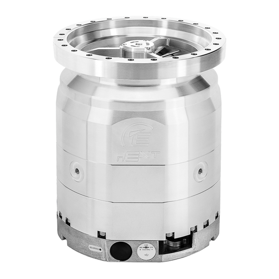
B8J200880_D - Overview 3. Overview A nEXT730D, nEXT930D or nEXT1230H pump consists of a turbomolecular pump with a permanently attached motor controller containing drive electronics. The motor controller controls the electrical supply to the pump. It allows manual adjustment of the standby speed and all other controls can only be operated through the logic interface. -
Page 14: Motor Controller
(INV versions) Figure 1 nEXT Model overview nEXT930D DN 200 CF nEXT730D DN 160 CF nEXT930D DN 200 ISO-K nEXT730D DN 160 ISO-K nEXT1230H DN 200 CF... -
Page 15: Operational Features
47. There is a USB port (item 9) which is a service port to be used with the Edwards nST2 PC software, using a standard micro-USB cable. This will enable the pump to be configured, monitored and upgraded without disconnecting from the 48 V d.c. supply. This software is available for download from the Edwards' Upgrade website: www.upgrades.edwardsvacuum.com. -
Page 16: Standby Speed
50%. 3.3.4 Analogue output The motor controller can produce an analogue output for monitoring system parameters. ▪ Measured pump rotational speed (default condition) ▪ Measured link power ▪ Measured motor temperature B8J200880_D Page 16 08/2021 - ©Edwards Limited 300812671_002_C3... -
Page 17: Automatic Vent Options
70 for instructions on altering the normal speed setting. 3.3.7 Electronic braking The pump has a user selectable electronic braking option that is disabled by default. With this option disabled, the pump will draw power from the electrical supply B8J200880_D Page 17 08/2021 - ©Edwards Limited 300812671_002_C3... -
Page 18: Bearing Monitoring
(refer to Connection for serial control and monitoring on page 59). The logic interface can be plugged directly into the Edwards TIC Turbo Controller, TIC Turbo Instrument Controller or TAG Controller and then use the functionality that they B8J200880_D Page 18 08/2021 - ©Edwards Limited... -
Page 19: Usb Interface
The simple parallel interface is a quick and easy way to control the pump. This is the same interface used on existing 24 V Edwards Turbo Pumps. The controls that are available to use are start and standby. The system status can be monitored using the normal, fail and analogue output signals. -
Page 20: Serial Control With Parallel Monitoring
USB service port. If using the USB service port in conjunction with Edwards nST2 PC software, the serial enable signal does not need to be linked to 0 V for the serial communications to take place. - Page 21 The USB service port can also be used in conjunction with the Edwards nST2 PC software to configure the nEXT pump. The configuration can then be downloaded to another nEXT pump, in the same way as it can with a TIC, which is useful when configuring a number of nEXT pumps.
-
Page 22: Technical Data
85 % RH (non‑condensing) Maximum operating altitude 4000 m (de-rated above 2000 m) Ambient storage temperature range -15 °C to 70 °C 4.2 General technical data Table 3 Technical data nEXT730D, nEXT930D nEXT 730D 730D 930D 930D High-vacuum connection... - Page 23 Table 4 Technical data nEXT1230H nEXT 1230H High-vacuum connection 200 CF 200 ISO-F 200 ISO-K Forevacuum connection 40 KF Pumping speed for 1250 1150 I · s 1350 1150 B8J200880_D Page 23 08/2021 - ©Edwards Limited 300812671_002_C3...
- Page 24 Recommended forevacuum pumps XDS35i or E2M28 Noise level with convection cooling dB(A) < 44 with radial air cooler < 55 Max. bake-out temperature of the CF °C – – version, water cooled B8J200880_D Page 24 08/2021 - ©Edwards Limited 300812671_002_C3...
-
Page 25: Pumping Speed Curves
G 1/8" * Depending on the ambient temperature, the gas throughput and the type of gas, forced air cooling or water cooling may be necessary. 4.2.1 Pumping speed curves Figure 2 Pumping speed curves for nEXT730D 1.000 nEXT730D Nitrogen Helium... -
Page 26: Figure 3 Pumping Speed Curves For Next930D
Figure 3 Pumping speed curves for nEXT930D 1.000 nEXT930D Nitrogen Helium Hydrogen Argon Inlet pressure in mbar Figure 4 Pumping speed curves for nEXT1230H 1.600 1.400 nEXT1230H 1.200 1.000 Helium Nitrogen Argon Hydrogen Inlet pressure in mbar B8J200880_D Page 26 08/2021 - ©Edwards Limited 300812671_002_C3... -
Page 27: Figure 5 Dimensional Drawing For Next730-930D
3. 48 V d.c. power supply cable, 0.6 m long incl. plug 4. Control interface cable, 0.95 m long incl. plug 1. 1. Table 5 Dimensions in mm nEXT730D 160 ISO-K nEXT730D 160 CF 202.5 nEXT930D 200 ISO-K 241.3 nEXT930D 200 CF 246.8 B8J200880_D Page 27 08/2021 - ©Edwards Limited 300812671_002_C3... -
Page 28: Figure 6 Dimensional Drawing For Next1230H
4. 48 V d.c. power supply cable, 0.6 m long incl. plug 5. Control interface cable, 0.95 m long incl. plug Table 6 Dimensions in mm nEXT1230H 200 CF 320.1 nEXT1230H 200 ISO-K 290.1 nEXT1230H 200 ISO-F 292.6 B8J200880_D Page 28 08/2021 - ©Edwards Limited 300812671_002_C3... -
Page 29: Pumping Media
Failure to contact the supplier may invalidate the warranty of the pump. The pump is not suitable for pumping aggressive or corrosive gases. Refer to the Edwards Vacuum Pump and Vacuum Safety manual P40040100 for safety information associated with the specification, design and operation of vacuum pumps and vacuum systems. -
Page 30: Vent Gas Specification And Vent Control Data
The following materials and component types are exposed to the gases pumped: ▪ Steel and aluminium alloys ▪ Fluoroelastomer and O‑rings ▪ Hydrocarbon lubricant ▪ ▪ Rare earth magnets ▪ Silicon nitride B8J200880_D Page 30 08/2021 - ©Edwards Limited 300812671_002_C3... -
Page 31: Purge Gas Specification
15 °C) Water temperature range 10 °C to 40 °C Maximum water pressure 5 bar (gauge), 72.5 psig, 5 x 10 Pa gauge Materials exposed to cooling water Brass and nickel plated brass B8J200880_D Page 31 08/2021 - ©Edwards Limited 300812671_002_C3... -
Page 32: Figure 8 Maximum Relative Humidity To Avoid Condensation With Water Cooling
B8J200880_D - Technical data Figure 8 Maximum relative humidity to avoid condensation with water cooling B8J200880_D Page 32 08/2021 - ©Edwards Limited 300812671_002_C3... -
Page 33: Figure 9 Cooling Requirements For Next730D/930D
B8J200880_D - Technical data Figure 9 Cooling requirements for nEXT730D/930D nEXT 730D and 930D - for Nitrogen 14.0 12.0 10.0 10.5 12.0 13.5 15.0 16.5 18.0 Pressure in mbar nEXT 730D and 930D - for Argon 10.2 11.7 13.2 14.7 16.2 17.7... -
Page 34: Electrical Data
Water cooling 35 °C, 50 l/h 4.8 Electrical data The nEXT pumps can be driven by either the customers system or by the Edwards TIC Turbo Instrument Controller, TIC Turbo Controller or TAG Controller. If using the customer system, an appropriate, pre-approved, UL/CSA rated 48 V d.c. -
Page 35: Logic Interface Connector
Table: Logic interface technical data. If the facility to adjust the power limit setting is not available, use a power supply capable of delivering enough current to meet the Edwards factory default power limit setting, shown in Table: Logic interface technical data. - Page 36 Logic low when pump rotational speed NORMAL status output is at normal speed or above 8, 13, 14 Electrical supply: 0 V 1, 6, 11 Electrical supply: 24 V - Positive 48 V d.c. B8J200880_D Page 36 08/2021 - ©Edwards Limited 300812671_002_C3...
-
Page 37: Serial Protocol
80 characters, including start and end characters. Note: All alphabetical characters must be sent in upper case format. The response may contain lower case characters. B8J200880_D Page 37 08/2021 - ©Edwards Limited 300812671_002_C3... - Page 38 Refer to Multi-drop operation on page 46 for more information about operating the nEXT pumps in multi-drop mode. B8J200880_D Page 38 08/2021 - ©Edwards Limited 300812671_002_C3...
-
Page 39: Command Set
!S854 1..30 decimal minutes Timeout period for both initial ramp up and if speed drops below 50% ?S854 Power limit setting !S855 nEXT730/930D: decimal Watts Link power maximum 190..600 nEXT1230H: 300..800 ?S855 B8J200880_D Page 39 08/2021 - ©Edwards Limited 300812671_002_C3... - Page 40 Set target speed to full speed Set target speed to standby speed Timer options !S870 decimal Timer = disabled ?S870 Timer = enabled Note that the timer is permanently ena- bled on ramp-up. B8J200880_D Page 40 08/2021 - ©Edwards Limited 300812671_002_C3...
- Page 41 (power cycle is required) Service status ?V881 32 bits flags Service status word Controller run time ?V882 0..999999 decimal hours Hours run by controller 0..999999 decimal hours Hours until controller service due B8J200880_D Page 41 08/2021 - ©Edwards Limited 300812671_002_C3...
- Page 42 If fail, hard vent If stop, controlled vent > 50% speed then hard vent < 50% speed Hard vent if stop or fail Same as option 6 Output is permanently energised (Fan B8J200880_D Page 42 08/2021 - ©Edwards Limited 300812671_002_C3...
- Page 43 If fail, hard vent If stop, controlled vent > 50% speed then hard vent < 50% speed Hard vent if stop or fail Same as option 6 Output is permanently energised (Fan B8J200880_D Page 43 08/2021 - ©Edwards Limited 300812671_002_C3...
- Page 44 Bearing inactive time !C893 decimal Reset bearing inactivity hours Real Time Clock ?V895 0..3599996400 Date and time This is UTC represented in seconds since start of the year 2000 i.e. since 2000/01/01 00,00,00 B8J200880_D Page 44 08/2021 - ©Edwards Limited 300812671_002_C3...
- Page 45 B8J200880_D - Technical data Object name Command Parameter range Factory set- Data type Units Comments ting Bearing Inactivity !S896 0..1 decimal 0: BCON Automatic Disable (Automatic Bearing ?S896 1: BCON Automatic Enable Conditioning) B8J200880_D Page 45 08/2021 - ©Edwards Limited 300812671_002_C3...
-
Page 46: Multi-Drop Operation
Figure 12 Conceptual diagram for multi-drop connection using RS232 interface 1. RS232 interface on control equipment 1. RS232 interface on control equipment 2. Buffer 2. Buffer 3. nEXT pump 3. nEXT pump 4. OR gate 4. OR gate B8J200880_D Page 46 08/2021 - ©Edwards Limited 300812671_002_C3... -
Page 47: Motor Controller Auxiliary Connector Socket
Vent option 1 and Valve 1 type and Aux output 2 is configured via Vent option 2 and Valve 2 type (refer to Vent valve control on page 77). Aux output 1 has B8J200880_D Page 47 08/2021 - ©Edwards Limited 300812671_002_C3... -
Page 48: Indicator Leds
Aux output 2 has default settings for a fan. Edwards nEXT air coolers and vent valve accessories (refer to Accessories), which have the corresponding connector fitted, are pre-configured to Aux output 1 and Aux output 2 for convenience and to provide plug and play ability. - Page 49 This blue LED illuminates or flashes when a bearing service Bearing LED activity is due or ongoing. Refer to Table: Bearing LED. Note: If an external electrical load is connected to the Normal output line, the normal LED may illuminate. B8J200880_D Page 49 08/2021 - ©Edwards Limited 300812671_002_C3...
-
Page 50: Installation
It is advised to retain all packing materials for use, should you return the pump for service. Table 15 Checklist of items Quantity Description Check nEXT730D, nEXT930D or nEXT1230H Turbomolecular Vac- ❏ uum Pump Integral mesh centering ring O-ring seal (ISO variants only. ❏ Screen will be fitted to CF pumps.) -
Page 51: Connect To The Vacuum System
When installing the vacuum pump, first mechanically connect the inlets and outlets and then make the electrical connections. CAUTION: VACUUM Pulling into the vacuum can cause injury to hands or fingers. Do not operate the vacuum pump with open flanges. B8J200880_D Page 51 08/2021 - ©Edwards Limited 300812671_002_C3... -
Page 52: Remove And Replace The Inlet Screen
To remove the inlet screen from a pump with CF inlet flange, use a bent wire hook or small screwdriver to carefully lever the inlet screen out from the inlet flange. B8J200880_D Page 52 08/2021 - ©Edwards Limited 300812671_002_C3... -
Page 53: Mounting Orientation
If they are not already in place, the tangs must be snapped into the locating groove in the inlet flange using a suitable tool to press them into position. For ISO flanged pumps, Edwards supplies a combination inlet screen/trapped O-ring. 5.2.2 Mounting orientation... -
Page 54: Mount The Pump
35 ▪ If the pump has an ISO-F flange, use the Edwards inlet screen supplied with the pump, a centering ring with O-ring and use a minimum of 12 bolts M10 (Bolt quality: 8.8 according to EN ISO 898-1 with coating, each torqued to 35 Nm) to connect the inlet flange of the pump to the vacuum system. -
Page 55: Backing Port Connection
B8J200880_D - Installation 5.2.4 Backing port connection The pump is suitable for use with Edwards Rotary Vane, Scroll or diaphragm backing pumps. System performance may depend upon which pump is used. Contact Edwards when selecting an appropriate backing pump for the application. -
Page 56: Earth (Ground) Connections
TIC or TAG, and the nEXT pump is powered separately using the Edwards power supply or alternatively the customer power supply connected to the pump via the dedicated nEXT pump power supply cable. -
Page 57: Connect The Logic Interface To Control Equipment
To operate the nEXT pump using the customer’s own electrical supply, use a suitable connector mating half (not supplied) to connect the electrical supply to the connector on the pump power supply cable. B8J200880_D Page 57 08/2021 - ©Edwards Limited 300812671_002_C3... -
Page 58: Connect The Parallel Control And Monitoring
59 for further details. To monitor the normal status output, connect the customer control equipment to the normal status output (pin 15) and to pin 2 of the customer logic interface mating half. B8J200880_D Page 58 08/2021 - ©Edwards Limited 300812671_002_C3... -
Page 59: Connection For Serial Control And Monitoring
5.6 Connection for serial control and monitoring The serial interface allows the nEXT pump to be controlled and to be interrogated as to its operational status using a number of serial commands or the nST2 PC software. There B8J200880_D Page 59 08/2021 - ©Edwards Limited 300812671_002_C3... -
Page 60: Connect The Serial Interface To The Customer Control Equipment
RS232 interface. Conversely when the RS485 option is selected, connecting several nEXT pumps to a single master becomes a simple wiring exercise as shown in Figure: RS485 multi-drop connection. B8J200880_D Page 60 08/2021 - ©Edwards Limited 300812671_002_C3... -
Page 61: Serial Enable
Link the serial enable input signal (pin 5) to pin 2 of the customer logic interface mating half. Edwards recommends incorporating this link into the serial communications cable so that the serial enable is only activated when the serial cable is connected. When the cable is removed, serial enable will become inactive. -
Page 62: Connection For Mixed Parallel And Serial Operation
USB service port using the Edwards nST2 PC software. Alternatively, the pump can be controlled using commands sent over the serial interface while at the same time monitoring the normal signal and analogue output over the parallel interface. -
Page 63: Cooling
Pump performance may be affected if you do not cool the pump and nEXT motor controller adequately. Edwards recommends that, wherever possible, the pump is cooled by forced air cooling or water cooling. -
Page 64: Forced Air Cooling
1. Hose connections for 6x1 hose 1. Hose connections for 6x1 hose The nEXT1230H pump has a built-in cooling water block as standard. For nEXT730D and nEXT930D: Attach the cooling water block to the pump with four M4 screws, tightening torque is 3 B8J200880_D Page 64 08/2021 - ©Edwards Limited... - Page 65 Either of the two push fit connectors on the water cooler can be used for the water supply or return connections. B8J200880_D Page 65 08/2021 - ©Edwards Limited 300812671_002_C3...
-
Page 66: Configuration
Configure the pump using serial commands on page 66 details the commands that will be needed to configure the motor controller. Alternatively use the Edwards TIC Turbo and Instrument Controller, TIC Turbo Controller or TAG Controller. Further information regarding this is detailed in Configure the pump using a TIC on page 74. -
Page 67: Message Structure
46. 6.1.2 Command and reply table definitions Explanation of the command and reply characters. Table 16 Command abbreviations Meaning Abbreviation Carriage return character chars Characters Decimal ASCII character Hexadecimal ASCII character B8J200880_D Page 67 08/2021 - ©Edwards Limited 300812671_002_C3... -
Page 68: Power Limit Setting
The Power Limit Setting is now stored in memory within the nEXT pump. To check what power limit is set, send a query as follows: Command The reply will be in the following format: B8J200880_D Page 68 08/2021 - ©Edwards Limited 300812671_002_C3... -
Page 69: Powering A Fan From The Motor Controller
To set the valve type on auxiliary output 1, send the following command, (where the character 'd' refers to the option number shown in Table: Valve types): Reply The reply will be in the following format: B8J200880_D Page 69 08/2021 - ©Edwards Limited 300812671_002_C3... -
Page 70: Standby Speed Setting
When the pump is shipped, it is configured with a normal speed of 80% full rotational speed. To change the normal speed setting, send the following command (where the characters 'd' represent the value as a percentage of full rotational speed): Command B8J200880_D Page 70 08/2021 - ©Edwards Limited 300812671_002_C3... -
Page 71: Timer Setting And Options
The state of the timer option is stored in memory within the nEXT pump. To enable the timer again, send the following serial command: Command The reply will be as follows: Reply B8J200880_D Page 71 08/2021 - ©Edwards Limited 300812671_002_C3... -
Page 72: Analogue Signal Options
The reply will be as follows: Reply The state of the Electronic Braking option is stored in memory within the nEXT pump. To disable the Electronic Braking again, send the following serial command: Command B8J200880_D Page 72 08/2021 - ©Edwards Limited 300812671_002_C3... -
Page 73: Factory Settings
A query can be sent to the pump to find out if it has a multi-drop address. Send the following command: Command If the reply is as follows, the pump has multi‑drop mode disabled: B8J200880_D Page 73 08/2021 - ©Edwards Limited 300812671_002_C3... -
Page 74: Configure The Pump Using A Tic
Once multi-drop mode is disabled, the pump will no longer respond to multi-drop commands. 6.1.13 Configure the pump using a TIC The nEXT pump can be configured using the Edwards TIC Turbo and Instrument Controller or TIC Turbo Controller. Refer to TIC or TAG logic interface connections on page 56. -
Page 75: Operation
Switch on the power supply to the pump. Check that the three normal, status and alarm LEDs on the motor controller light up for approximately 0.5 seconds and then extinguish. Check that the bearing LED is off. B8J200880_D Page 75 08/2021 - ©Edwards Limited 300812671_002_C3... -
Page 76: Vent Options, Vent Valve Connection And Control
7.2.1 Manual vent valve Edwards recommends that the manual vent valve is opened only after the pump speed has fallen to 50% of full rotational speed. A manual vent valve is supplied with the nEXT pump. It is not possible to accurately control the rate of pressure rise using the manual vent valve so take care not to open it too quickly. -
Page 77: Vent Valve Control
7.2.3 Vent valve control The TAV solenoid valve can be controlled by the nEXT motor controller or by an Edwards TIC Turbo Instrument Controller. The nEXT controller can control the rate of venting, using the vent valve options in... - Page 78 The controller can be configured to one of the other venting options provided commands can be sent via the serial interface, an Edwards TIC Turbo and Instrument Controller, TIC Turbo Controller, or the Edwards nST2 PC software can be used via the USB serial port.
-
Page 79: Alternative Valve Connected To The Vacuum System
B8J200880_D - Operation If the nEXT pump is being controlled with an Edwards TIC Turbo and Instrument Controller or TIC Turbo Controller, the TAV solenoid valve can be driven from the TIC. Refer to the TIC Instruction Manuals for more information. -
Page 80: Run The Pump At Standby Speed With Parallel Control
This allows the backing pump to reduce the pressure in the vacuum system. To close the vent valve, send the following command: Command The reply will be in the following format: Reply B8J200880_D Page 80 08/2021 - ©Edwards Limited 300812671_002_C3... -
Page 81: Start The Pump With Serial Control
To run the nEXT pump at standby speed, send the following command over the serial communications link: Command The reply will be in the following format: Reply To return the pump to full speed, send the following command: B8J200880_D Page 81 08/2021 - ©Edwards Limited 300812671_002_C3... -
Page 82: Stop The Pump With Serial Control
(measured in 0.1 Watts): Reply sp d 7.4.7 Monitor measured motor speed with serial control The measured rotational speed of the motor inside the nEXT pump can be monitored. Send the following query: Command B8J200880_D Page 82 08/2021 - ©Edwards Limited 300812671_002_C3... -
Page 83: Mixed Parallel And Serial Operation
RS485/CAN/RS232 switch is in the RS485 position. In parallel control mode, the pump will not accept serial stop commands but will accept all other serial commands. When serial enable is active, the pump will run at standby B8J200880_D Page 83 08/2021 - ©Edwards Limited 300812671_002_C3... -
Page 84: Operation With A Tic Or Tag
Figure 27 Serial and parallel control flowchart 7.6 Operation with a TIC or TAG The nEXT pump can be connected directly to an Edwards TIC Turbo Instrument Controller, TIC Turbo Controller or TAG Controller. Instructions on the setup and operation with the TIC Turbo Instrument Controller, TIC Turbo Controller or TAG Controller can be found on CD ROM part number P450-00-000, which is supplied with the TIC or TAG. -
Page 85: Operation At Extreme Conditions
50% of full rotational speed. Refer to Table: Operating and storage conditions for pump operating ranges and Cooling on page 63 for advice on pump cooling. B8J200880_D Page 85 08/2021 - ©Edwards Limited 300812671_002_C3... -
Page 86: Protection Against Over-Speed
The motor controller will signal a fail condition if over‑speed has been detected. If the pump appears to be running at over-speed, switch it off and consult Edwards or the supplier. 7.8.4 Electrical supply failure If the electrical supply to the nEXT pump fails when the pump is rotating, the pump motor is used as a generator. -
Page 87: Bakeout
The pump may only be heated on the flange with the flange heaters provided for this purpose from the accessories. Heating the pump will also prevent condensation of vapours inside the pump. B8J200880_D Page 87 08/2021 - ©Edwards Limited 300812671_002_C3... -
Page 88: Shut Down The Pump Manually
The Edwards flange heater may be used to heat the pump (refer to Accessories). Fit the appropriate band around the pump CF inlet flange. When baking the pump or the system, make sure that the temperature of the inlet flange does not exceed the values specified in . -
Page 89: Maintenance
90 The fatigue life of nEXT Turbomolecular pump rotors is typically 40,000 to 50,000 cycles. As a precautionary measure, Edwards rec- ommends that pumps are returned for a major service (rotor re- placement) after 20,000 cycles of acceleration to full speed and back to a stop, or after ten years of use, whichever occurs first. -
Page 90: Rotor Life
105. Any organic solvent can be used to clean the external surfaces of the pump. Edwards recommend the use of non-CFC solvents such as isopropanol or ethanol. Only a minimal amount of a cleaning solution is required which is suitable for the contaminants on the pump surfaces. - Page 91 Per bit 8, but suppressed if bit 11 or 12 set quired BR required Per bit 9, but suppressed if bit 12 set Bearing conditioning Set if Bearing conditioning is presently run- running ning, from start to Post Ramp (PR) com- mence B8J200880_D Page 91 08/2021 - ©Edwards Limited 300812671_002_C3...
-
Page 92: Controller Run Time
Command The reply will be as follows, where the first number is the start-stop cycles completed by the pump and the second is the number of start-stop cycles until service is recommended: B8J200880_D Page 92 08/2021 - ©Edwards Limited 300812671_002_C3... -
Page 93: Bearing Run Time
The reply will be as follows, where the first number is the hours run by the bearing and the second is the number of hours until service is recommended: Reply sp d B8J200880_D Page 93 08/2021 - ©Edwards Limited 300812671_002_C3... -
Page 94: Storage
Store the pump in cool, dry conditions, preferably not exposed to atmospheric air until required for use. When required, prepare and install the pump as described in Installation on page 50. B8J200880_D Page 94 08/2021 - ©Edwards Limited 300812671_002_C3... -
Page 95: Disposal
Take appropriate action to avoid inhalation of any particles that may be present in the pump. Do not incinerate the pump. The pump contains phenolic and fluorosilicone materials that can decompose to very dangerous substances when heated to high temperatures. B8J200880_D Page 95 08/2021 - ©Edwards Limited 300812671_002_C3... -
Page 96: Fault Finding
If there is no reply then perform the checks given under No serial comms on page 98 otherwise perform the checks under The pump does not rotate after a serial start command is sent on page 96. B8J200880_D Page 96 08/2021 - ©Edwards Limited 300812671_002_C3... -
Page 97: The Pump Does Not Respond In Multi- Drop Mode
▪ Check that external heat sources (such as system bakeout heaters) are not excessive. Cause The rotor does not rotate freely. Remedy The pump bearings may be damaged. Contact the supplier or Edwards. Fault Ultimate pressure cannot be reached Cause Pressure is limited by water vapour. -
Page 98: The Pump Is Very Noisy Or There Is Excessive Vibration Or Both
▪ Leak test the pump. If the leak rate > 1x10 mbar l s (1x10 Pa l s contact the supplier or Edwards. Fault The pump is very noisy or there is excessive vibration or both Cause The pump rotational speed is the same as the resonant frequency of the attached system. -
Page 99: Command Set Error Codes
Contact the supplier or us. 11.1 Command set error codes Error codes that may be returned for serial control and monitoring. Table 26 Command error codes Meaning Returned error code No error B8J200880_D Page 99 08/2021 - ©Edwards Limited 300812671_002_C3... -
Page 100: Flashing Service Codes
In this case, try cycling the power. If cycling the power does not clear the indiwill be required. Contact the supplier or Edwards. If the alarm LED is flashing, identify the error flash code and consult the table in Decoding system status words page 102. -
Page 101: Flashing Inactivity Service Codes (Blue Bearing Led)
The pump has been stored or has not been run LED on 0.25s Bearing service recom- for more than 3 years. It is recommended that mended LED off 0.25s the bearing is replaced. B8J200880_D Page 101 08/2021 - ©Edwards Limited 300812671_002_C3... -
Page 102: Decoding System Status Words
(starting with 0 for the least significant to 31 for the most significant) as shown below. contains a list of the lower 16 status flags that will be useful for fault finding. The upper 16 status flags are reserved by us. B8J200880_D Page 102 08/2021 - ©Edwards Limited 300812671_002_C3... - Page 103 The pump has not failed The pump is at rest Speed is below normal speed The vent valve is open There is no active start command Serial enable is active Standby is not active B8J200880_D Page 103 08/2021 - ©Edwards Limited 300812671_002_C3...
-
Page 104: Service Information
String 3 cr Send the following query to find out the PIC software version: Command The reply is as follows, where String 1 is the PIC software version number: Reply String 1 B8J200880_D Page 104 08/2021 - ©Edwards Limited 300812671_002_C3... -
Page 105: Service
Do not return a pump with accessories fitted. Remove all accessories and retain them for future use. ▪ The instruction in the returns procedure to drain all fluids does not apply to the lubricant in pump oil reservoirs. B8J200880_D Page 105 08/2021 - ©Edwards Limited 300812671_002_C3... -
Page 106: Bearing Monitoring And Conditioning System
12.3 Bearing on-site maintenance The bearing of the nEXT pump can be serviced on‑site by any service engineer trained by The following service tool kits and service parts are available. B8J200880_D Page 106 08/2021 - ©Edwards Limited 300812671_002_C3... -
Page 107: Bearing Run In Mode
B8J200880_D - Service Table 33 Service tool kits Service tool kit Item number Bearing exchange tool kit nEXT730D/930D B8J200845 Bearing exchange tool kit nEXT1230H B8M200845 Table 34 Service kits Service kit Item number Bearing kit nEXT730D/930D B8J200827 Bearing kit nEXT1230H B8M200827 12.4 Bearing run in mode... -
Page 108: Spares
ISO 160 trapped O-ring with integrated fine inlet B80000826 screen DN 200 ISO-K ISO 200 trapped O-ring with integrated coarse inlet B8J200807 screen DN 200 ISO-K ISO 200 trapped O-ring with integrated fine inlet B8J200808 screen B8J200880_D Page 108 08/2021 - ©Edwards Limited 300812671_002_C3... -
Page 109: Accessories
The EPS 800 can be fitted to the pump or utilized as a benchtop on page 113 unit. 14.1 Air cooler The air coolers are available with a pre-wired connector which connects directly to an auxiliary port on the controller. B8J200880_D Page 109 08/2021 - ©Edwards Limited 300812671_002_C3... -
Page 110: Water Cooler
The flange heaters are available in 110 V and 240 V versions. Note: The flange heater is only for use with CF variants. Table 40 Flange heater Flange heater Item Number nEXT730D (110 V) flange heater B58052775 nEXT730D (240 V) flange heater B58052776 nEXT930D (110 V) flange heater on request... -
Page 111: Vrx Vent Restrictor
The PRX10 is a modified DN10NW centring ring that filters the purge gas and restricts its flow rate to the recommended flow of 25 sccm. A vent port adaptor must be fitted to the purge port in order to connect a purge restrictor to the pump. B8J200880_D Page 111 08/2021 - ©Edwards Limited 300812671_002_C3... -
Page 112: Interface Cable
It can be used to control, monitor, configure and data log the nEXT pump, and also to view service status, reset service intervals and upgrade the software embedded in the motor controller. This software is available for download from the Edwards upgrades website: www.upgrades.edwardsvacuum.com 14.10 Auxiliary connector Enables the use of accessories that do not come prewired with a mating plug. -
Page 113: Auxiliary 'Y' Cable Adaptor
Mains cable, 3 m CA-3-LD US B8J200830 Mains cable, 3 m CA-3-LD UK B8J200831 Extension cable nEXT, 3 m B8J200824 (between pump and power supply) Extension cable nEXT, 5 m B8J200825 (between pump and power supply) B8J200880_D Page 113 08/2021 - ©Edwards Limited 300812671_002_C3... - Page 114 B8J200880_D - Accessories Item Item Number Bracket for mounting the EPS 800 to the B8J200832 pump (washers and bolts enclosed) B8J200880_D Page 114 08/2021 - ©Edwards Limited 300812671_002_C3...
- Page 115 B8J200880_D - Accessories B8J200880_D Page 115 08/2021 - ©Edwards Limited 300812671_002_C3...
- Page 116 EU Declaration of Conformity Edwards Ltd Documentation Officer Innovation Drive Jana Sigmunda 300 Burgess Hill Lutín , 78349 West Sussex Czech Republic RH15 9TW T: +42(0) 580 582 728 documentation@edwardsvacuum.com The product specified and listed below Turbomolecular Pumps with Integrated Frequency Converter •...
- Page 117 You must retain the signed legal declaration for future reference This declaration becomes invalid if modifications are made to the product without prior agreement. Signed for and on behalf of Edwards Ltd Ian Keech – VP Engineering, Scientific Vacuum Division Axel Guddas –...
- Page 118 ADDITIONAL LEGISLATION AND COMPLIANCE INFORMATION RoHS (EU, UK): Material Exemption Information This product is compliant with the following Annex III Exemptions: 6(a) Lead as an alloying element in steel for machining purposes and in galvanised steel containing up to 0.35 % lead •...
- Page 119 This page has been intentionally left blank.
- Page 120 edwardsvacuum.com...
Need help?
Do you have a question about the nEXT730D and is the answer not in the manual?
Questions and answers