Page 3
Declaration of Conformity Edwards Ltd, Innovation Drive, Burgess Hill, West Sussex, RH15 9TW, UK The following product: Product designation : nES, 
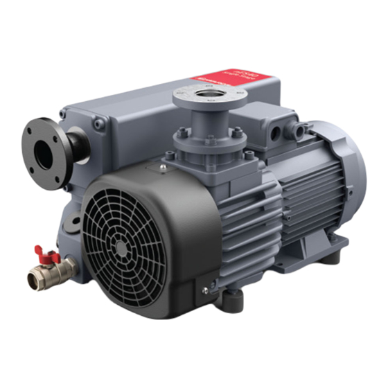
Single Stage Rotary Vane Pumps Type designation: 40 / 65 / 100 / 200 / 300 / 470 / 570 / 630 / 750...
Page 4
P200-10-204 Issue A Material Declaration In accordance with the requirements of the Chinese regulatory requirement on the Management Methods for the Restriction of the Use of Hazardous Substances in Electrical and Electronic Products Order No. 32 (also known as ‘China RoHS2’) and SJ/T 11364 Marking for the Restricted Use of Hazardous Substances in Electronic and Electrical Products: Product Product Labels...
Page 5
This page has been intentionally left blank.
Page 6
This page has been intentionally left blank.
A35104880_B - Safety and compliance 1. Safety and compliance 1.1 Definition of Warnings and Cautions NOTICE: For safe operation from the start, read these instructions carefully before you install or commission the equipment. Read all the safety instructions in this section and the rest of this manual carefully and make sure that you obey these instructions.
A35104880_B - Safety and compliance Warning/Caution An appropriate safety instruction must be followed or caution to a potential hazard exists. Warning - Dangerous voltage Identifies possible hazards from dangerous voltages. Warning - Hot surfaces Identifies a potential hazard from a hot surface. Warning - Use protective equipment Use appropriate protective equipment for the task.
A35104880_B - Safety and compliance The operator must follow safe working practices and observe all related work safety requirements and regulations. If any of the following statements does not comply with the applicable legislation, the stricter of the two shall apply. Installation, operation, maintenance and repair work must only be performed by authorised, trained and specialised personnel.
A35104880_B - Safety and compliance sure that there is no one checking or working on the machine. A suitable notice must be affixed to the start equipment. Air-cooled machines must be installed to make sure adequate flow of cooling air is available and that the exhausted air does not recirculate to the inlet.
A35104880_B - Safety and compliance Never operate the machine below or above its limit ratings. Keep all bodywork doors shut during operation. The doors may be opened for short periods only, for example, to do routine checks. Wear ear protectors when opening a door.
Page 15
A35104880_B - Safety and compliance A warning sign bearing a legend such as "Work in progress; do not start" shall be attached to the starting equipment. Persons switching on remotely controlled machines shall take adequate precautions to ensure that there is no one checking or working on the machine. To this end, a suitable notice shall be affixed to the remote start equipment.
A35104880_B - Description 2. Description 2.1 General description The nES40 to nES750 are single-stage, oil-sealed and air or water-cooled rotary vane vacuum pumps driven by an electric motor. nES470, nES570, nES630 and nES750 are belt driven. The pumps have been specifically designed to work with clean air, inert gas or small amounts of water vapour.
A35104880_B - Technical data 3. Technical data 3.1 References conditions and limitations Table 1 References conditions and limitations Parameter Unit 300S mbar(g) 1013 Ambient barometric Torr pressure (mmHg) °C Air inlet temperature °F Motor speed 1500 50 Hz Motor speed 1800 60 Hz Mineral oil...
A35104880_B - Technical data Note: Lower temperatures are possible with reduced viscosity oil. This temperature range is defined by Pneurop for performance conformity testing, but 8 °C is the critical point from the motor starting viewpoint. 3.2 Pump data Table 2 Pump data Parameter Unit 300S...
A35104880_B - Technical data Figure 10 nES750 Pumping performance curve 3.3 Motor data Refer to the specification on the motor nameplates. Page 20 - 07/2020...
A35104880_B - Installation 4. Installation 4.1 Dimension drawings Figure 11 nES40 Dimensions A. Lifting lug A. Lifting lug B. Gas ballast B. Gas ballast C. Exhaust port C. Exhaust port D. Cooling air D. Cooling air E. Space for exhaust filter exchange and E.
A35104880_B - Installation Figure 13 nES100 Dimensions A. Inlet port A. Inlet port B. Gas ballast B. Gas ballast C. Exhaust port C. Exhaust port D. Cooling air D. Cooling air E. Space for exhaust filter exchange and E. Space for exhaust filter exchange and F.
A35104880_B - Installation Figure 15 nES300 Dimensions A. Inlet port A. Inlet port B. Mounting (4) M10 x 10 B. Mounting (4) M10 x 10 C. Exhaust port C. Exhaust port D. Cooling air D. Cooling air E. Space for exhaust filter exchange and E.
A35104880_B - Installation Figure 17 nES470 Dimensions A. Inlet port A. Inlet port B. Exhaust port B. Exhaust port C. Mounting (4) M16 x 14 C. Mounting (4) M16 x 14 D. Lifting lug D. Lifting lug 07/2020 - Page 25...
A35104880_B - Installation Figure 18 nES570 Dimensions A. Inlet port A. Inlet port B. Exhaust port B. Exhaust port C. Mounting (4) M16 x 14 C. Mounting (4) M16 x 14 D. Lifting lugs D. Lifting lugs Page 26 - 07/2020...
A35104880_B - Installation Figure 19 nES630 Dimensions A. Inlet port A. Inlet port B. Exhaust port B. Exhaust port C. Oil level switch C. Oil level switch D. Motor connection D. Motor connection E. External filtration connection E. External filtration connection 07/2020 - Page 27...
A35104880_B - Installation Figure 20 nES750 Dimensions A. Inlet port A. Inlet port B. Exhaust port B. Exhaust port C. Oil level switch C. Oil level switch D. Motor connection D. Motor connection E. External filtration connection E. External filtration connection 4.2 Installation guidelines ▪...
Page 33
A35104880_B - Installation ▪ Install the pump on a solid, level surface, suitable for taking its weight. Respect the minimal distance between the pump and the walls (Refer to Dimension drawings on page 22). ▪ Correct process lines sizes must be used to prevent restrictions and resulting pressure drops.
A35104880_B - Installation ▪ When pumping condensible vapours and particulates, more frequent fluid changes are required to maintain pump life. Contact us about types and styles of filtration units. ▪ Make sure there is no backpressure in the exhaust line of the vacuum pump. Vacuum pumps are not specifically designed to compress exhaust gas above atmospheric pressure.
A35104880_B - Installation ▪ For pumps with a single-phase motor, the pump should be connected to a standard wall socket, a 16 A rated protection is necessary (fuse or breaker). The motor has a "Klixon" overload protection element which looks like a red push button that must be manually reset after an overload trip.
A35104880_B - Operation 5. Operation 5.1 Initial start-up WARNING: SAFETY PRECAUTIONS Risk of injury or damage to equipment. The operator must apply all relevant safety precautions. Refer to Safety precautions during operation on page 12 Safety precautions during operation on page 9. Note: The pump is supplied filled with oil.
A35104880_B - Operation 5.2 Start the pump CAUTION: EXCESSIVE ENERGY CONSUMPTION Risk of damage to equipment. To avoid excessive energy consumption and damage to the vacuum pump the maximum allowed starting frequency is 6 starts per hour. For more frequent operation, let the pump operate continuously and control the vacuum demand by a pitot valve on the pump inlet.
A35104880_B - Operation 5.5 Taking out of operation Note: The operator must apply all relevant safety precautions. Refer to Safety precautions during operation on page 12 Safety precautions during operation on page 9 and Fault finding on page 39 Fault finding on page 43.
A35104880_B - Maintenance 6. Maintenance 6.1 Preventive maintenance schedule WARNING: SAFETY PRECAUTIONS Risk of injury or damage to equipment. The operator must apply all relevant safety precautions. Refer to Safety precautions during maintenance or repair on page 10. Before the maintenance, repair or adjustments, do the steps as follow: ▪...
Always drain the pump well. Used oil left in the pump shortens the lifetime of the new oil. nES series pumps are delivered with mineral oil, Ultragrade Performance 70, or with synthetic oil, Ultragrade Extend 110. Check the pump nameplate.
A35104880_B - Maintenance 6.3 Service kits For overhauling and for preventive maintenance, a wide range of service kits is available. Service kits comprise all parts required for servicing the component and offer the benefits of our genuine parts while keeping the maintenance budget low. Also, a full range of extensively tested lubricants, suitable for your specific needs is available to keep the vacuum pump in excellent condition.
A35104880_B - Adjustments and servicing procedures 7. Adjustments and servicing procedures 7.1 Drive motor On nES100 - nES750 (nES40 - nES65 do not have motor bearings) the motor bearings must be changed every 20,000 hours. Check recommendations on the motor's website. If installed, remove the motor condensate drain plug yearly.
Page 43
A35104880_B - Adjustments and servicing procedures nES630, nES750 Tools required: Tubular box wrench 16 mm. When the exhaust filter elements are clogged, the integrated bypass opens and the filters are bypassed. Oil mist at the exhaust and high oil consumption are signs that the exhaust filters are clogged.
A35104880_B - Adjustments and servicing procedures 7.3 Oil and oil filter change WARNING: OIL CONTAMINATION Risk of damage to equipment. Always apply all relevant safety precautions. Refer to Safety precautions during maintenance or repair on page 10. Always drain the oil at all drain points. Used oil left in the pump can contaminate the oil system and can shorten the lifetime of the new oil.
A35104880_B - Adjustments and servicing procedures 7.4 Cleaning radiator, motor fan guard and pump The radiator, motor fan guard and pump must be kept clean. This can be done using compressed air and a dry cloth. Be careful not to damage the oil cooler (if applicable) by cleaning with compressed air or by exerting excessive pressure with the cloth.
A35104880_B - Adjustments and servicing procedures ▪ Install the tension meter as shown in picture 1, in the middle, halfway between the V‑belt contacts point of the V‑belts and the two pulleys. ▪ Push the Newton scale's black rubber down to reach a 10 mm bending of the V‑belt as shown in pictures 2 and 4.
A35104880_B - Fault finding 8. Fault finding Table 5 Fault finding Conditions The pump does not run on page 43 The pump cannot reach stated vacuum on page 43 Pump is noisy on page 43 Pump runs hot on page 44 High oil consumption on page 44 Pump does not maintain vacuum after power-off and pump leaks oil...
Page 48
A35104880_B - Fault finding Remedy Contact service department. Cause Motor coupling damaged (if applicable) Remedy Contact service department. Cause Vanes worn out Remedy Contact service department. Cause Solid particles in the oil Remedy Change oil. Fault Pump runs hot Cause Wrong oil type Remedy Replace oil.
Page 49
A35104880_B - Fault finding Cause Oil sight glass loose Remedy Tighten. Fault The expected process vacuum level is not reached Cause Too high-pressure drop between process and pump inlet Remedy Check the process lines for the correct size and leaks and correct if necessary. Cause Clogged air inlet filter element Remedy...
A35104880_B - Storage 9. Storage To keep rubber parts and lip seals efficient and working properly, we recommend the pump is operated for at least 30 minutes every 6 months with the inlet closed. Store the pump in its packing in a covered, dry place at a temperature between -20 °C (-4 °F) and 50 °C (122 °F).
A35104880_B - Disposal 10. Disposal Used filters or any other used material (for example, lubricants, cleaning rags and machine parts) must be disposed of in an environmentally friendly and safe manner, and in line with the local recommendations and environmental legislation. 10.1 Recycle the pump The contaminated parts can be dangerous for your health and environment.
A35104880_B - Disposal Recycle Description Component symbol Motor WEEE Frequency converter and electronics Figure 24 Components for recycling 07/2020 - Page 49...
11. Return the equipment or components for service Before you send your equipment to us for service or for any other reason, you must send us a completed Declaration of Contamination of Vacuum Equipment and Components – Form HS2. The HS2 form tells us if any substances found in the equipment are hazardous, which is important for the safety of our employees and all other people involved in the service of your equipment.