Edwards nEXT85 Instruction Manual
Hide thumbs
Also See for nEXT85:
- Original instructions manual (28 pages) ,
- Instruction manual (112 pages) ,
- Instruction manual (33 pages)

Related Manuals for Edwards nEXT85


Summary of Contents for Edwards nEXT85
- Page 1 INSTRUCTION MANUAL Publication Number: B8G0-00-880 Issue: A Original Instructions edwardsvacuum.com...
-
Page 2: Copyright Notice
B8G0-00-880A - Copyright notice Copyright notice © Edwards Limited 2016. All rights reserved. Trademark credits Edwards and the Edwards logo are trademarks of Edwards Limited. Page 2... -
Page 3: Declaration Of Conformity
EU authorised to assemble the technical file, that the product(s)* nEXT85 The material numbers cover a family of pumps where the following component features may vary according to the variant; ‘X’ denotes combinations of variants of the geometry of pump inlet ports, geometry or position of exhaust port and the material and geometry of the pump casing. - Page 4 P200-10-019 Issue B Material Declaration In accordance with the requirements of the Chinese regulatory requirement on the Management Methods for the Restriction of the Use of Hazardous Substances in Electrical and Electronic Products Order No. 32 (also known as ‘China RoHS2’) and SJ/T 11364 Marking for the Restricted Use of Hazardous Substances in Electronic and Electrical Products: Product Labels Product...
-
Page 5: Table Of Contents
Interstage connection.................... 25 Purge gas connection......................25 Recommended purge gas flow................25 Connect the purge gas................... 25 Electrical installation of the nEXT85 ................25 Earth (ground) connections................... 26 TIC or TAG logic interface connections..............26 Connect the logic interface to control equipment..........26 Connect the parallel control and monitoring.............. - Page 6 Electronic braking options..................41 Factory settings...................... 42 Assigning a multi-drop address................42 Configure the pump using a TIC..................43 Operation of the nEXT85 Before starting the pump....................44 Close the vent valve....................44 Pre-start sequence....................44 Vent options, vent valve connection and control............. 44 Manual vent valve....................45...
- Page 7 B8G0-00-880A - Contents Protection against over-speed................54 Electrical supply failure..................55 Bakeout..........................56 Shut down the pump manually..................57 Maintain the nEXT85 Bearing and oil cartridge maintenance................59 Rotor life........................... 59 Cleaning the pump......................59 Decoding service status words..................59 Controller run time......................60 Pump run time........................
- Page 8 B8G0-00-880A - Contents Inlet flange seals and integrated inlet screens..............76 NW16 and NW25 ports....................77 Accessories for the nEXT85 Air cooler.......................... 79 Water cooler........................79 Bakeout (heater) band...................... 80 TAV5 vent valve.........................80 VRX vent restrictor......................81 Vent port adaptor......................81 PRX purge restrictor......................81...
-
Page 9: List Of Figures
Figure 9: Serial and parallel control flowchart................53 Figure 10: Accessories......................... 79 Figure 11: Dimensions - nEXT85 ISO63..................84 Figure 12: Dimensions - nEXT85 CF63..................85 Figure 13: Dimensions - nEXT85 ISO100..................85 Figure 14: Dimensions - nEXT85 DN40..................85 Figure 15: Max allowed rate of pressure rise during venting: pressure against time (pump initially at full speed)...................... -
Page 10: List Of Tables
B8G0-00-880A - List of Tables List of Tables Table 1: Checklist of items......................19 Table 2: Water cooling block supply requirements..............34 Table 3: Command abbreviations....................36 Table 4: Power limit setting......................37 Table 5: Analogue signal options....................41 Table 6: Vent valve options......................46 Table 7: Valve types........................ -
Page 11: Safety And Compliance
Safety symbols The safety symbols on the products denote areas where care and attention is required. The following safety symbols may be used on the nEXT85 and throughout the product documentation. Warning/Caution - An appropriate safety instruction should be followed or caution to a potential hazard exists. -
Page 12: Overview Of The Next85
78). The TAV valve can be directly controlled by the on-board motor controller. The nEXT85 pumps have a purge port: an inert purge gas can be introduced to protect the bearing and motor from corrosion. An optional vent port adapter and purge restrictor can be fitted to the purge port to control the flow rate of the purge gas and to filter the gas supply. -
Page 13: Motor Controller
30) which is a service port to be used with the Edwards nST PC software, using a standard micro-USB cable. This will enable the pump to be configured, monitored and upgraded without disconnecting from the 24 - 48 V d.c. supply. This software is available for download from the Edwards' Upgrade website: www.upgrades.edwardsvacuum.com... -
Page 14: Power Limit Setting
37). Also ensure there is sufficient cooling for the application. Ensure that the power supply is capable of delivering sufficient power to the nEXT85 pump. By choosing a lower power limit setting, a smaller power supply may be used. For more... -
Page 15: Automatic Vent Options
Vent options, vent valve connection and control on page 44. In addition there is a feature that allows a delayed start of the nEXT85 pump. With this feature, the vent valve can be closed before starting the pump. This allows the backing pump to reduce the pressure in the vacuum system before starting the nEXT85 pump. -
Page 16: Logic Interface
The simple parallel interface is a quick and easy way to control the pump. This is the same interface used on existing 24 V Edwards Turbo Pumps. The controls that are available to use are start and standby. The system status can be monitored using the normal, fail and analogue output signals. -
Page 17: Serial Control And Monitoring
USB service port. If using the USB service port, in conjunction with Edwards nST PC software, the serial enable signal does not need to be linked to 0 V for the serial communications to take place. Whilst... -
Page 18: Motor Controller Configuration (Serial Configuration)
The USB service port can also be used in conjunction with the Edwards nST PC software to configure the nEXT85 pump. The configuration can then be downloaded to another nEXT85 pump, in the same way it can with a TIC, which is useful when configuring a number of nEXT85 pumps. -
Page 19: Install The Next85
B8G0-00-880A - Install the nEXT85 Install the nEXT85 Unpack and inspect The pump is supplied in a cardboard box and does not require lifting equipment. WARNING: Appropriate care should be taken when lifting and moving the pump to avoid injury. The user must adhere to manual handling guidelines. -
Page 20: Connect To The Vacuum System
B8G0-00-880A - Install the nEXT85 Figure 1 Typical pumping system with a nEXT pump 1. Vacuum system 10. Backing pump (Rotary vane or scroll 2. High vacuum gauge pump) 3. Vibration damper 11. Mist filter (for rotary pump) / silencer 4. -
Page 21: Remove And Replace The Inlet Screen
The NW40 inlet variant cannot be flange mounted. Backing port connection The pump is suitable for use with Edwards Rotary Vane, Scroll or diaphragm backing pumps. System performance may depend upon which pump is used. Contact Edwards when selecting an appropriate backing pump for the application. -
Page 22: Mount The Pump
10 Nm. Base mounting The base of the nEXT85 pump can be fixed to a firm support using the tapped fixing holes. Note: The four rubber feet must be removed from the four tapped fixing holes before the pump can be base mounted. - Page 23 Make sure that the pump inlet and all components fitted to the pump inlet are clean and dust- free. If the pump inlet is not kept clean, the pump-down time may be increased. The inlet connections for the nEXT85 pumps are either ISO flange, CF flange or NW40 flange. •...
-
Page 24: Backing Port Connection
Figure 2 Allowable pump orientation Backing port connection The pump is suitable for use with Edwards Rotary Vane, Scroll or diaphragm backing pumps. System performance may depend upon which pump is used. Contact Edwards when selecting an appropriate backing pump for the application. -
Page 25: Interstage Connection
(ground) point. The nEXT85 pump can be operated using the Edwards TIC Turbo Instrument Controller, TIC Turbo Controller or TAG Controller. The nEXT85 pump can also be powered by the customer supply and controlled using the customer system. Refer to... -
Page 26: Earth (Ground) Connections
If an Edwards TIC Turbo Instrument Controller, TIC Turbo Controller or TAG Controller are used to power and control the pump, the nEXT85 pump logic interface cable connects directly into the back of the TIC or TAG. Refer to the TIC or TAG Instruction Manuals for further information. -
Page 27: Connect The Parallel Control And Monitoring
The nEXT85 pump 0 V is not referenced to earth (ground). Ensure that there is only one path between 0 V and earth. Multiple connections between 0V and earth must be avoided in order to avoid unexpected offset voltages on control and status signals and possible problems with serial communications. -
Page 28: Connection For Serial Control And Monitoring
Connection for serial control and monitoring The serial interface allows the nEXT85 pump to be controlled and to be interrogated as to its operational status using a number of serial commands or the nST PC software. There is also a multi-drop mode that allows for the connection of more than one nEXT85 pump to a single serial port on the control system. -
Page 29: Connect The Serial Interface To The Customer Control Equipment
31. In this configuration the PC is the serial link master and the nEXT85 pump is the slave. The distance over which the serial link will work is dependent on any difference in voltage between the 0 V at the sending and receiving end. -
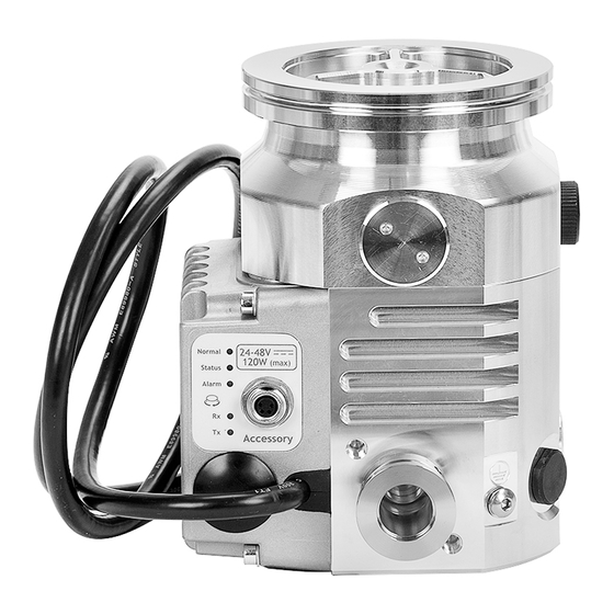
Page 30: Figure 4 Motor Controller Status Information
B8G0-00-880A - Install the nEXT85 Figure 4 Motor controller status information 1. Normal LED 6. Serial transmit LED 2. Status LED 7. Standby speed increase button 3. Alarm LED 8. RS232/RS485 slide switch 4. Accessory connector 9. USB connector 5. Serial receive LED 10. -
Page 31: Serial Enable
USB service port using the Edwards nST PC software. Alternatively, the pump can be controlled using commands sent over the serial interface while at the same time monitor the normal signal and analogue output over the parallel interface. -
Page 32: Cooling
Ensure that the pump is adequately cooled to prevent damage to the rotor and bearing. CAUTION: When using alternative cooling arrangements other than the standard Edwards cooling accessories, ensure cooling is not solely directed or ducted onto the pump controller. -
Page 33: Forced Air Cooling
100 m (60 cfm). The air cooler can be powered by a customer external power supply, the Edwards TIC Turbo and Instrument Controller, the TIC Turbo Controller or the nEXT85 Controller. Plug the... -
Page 34: Table 2 Water Cooling Block Supply Requirements
B8G0-00-880A - Install the nEXT85 1. Connect the cooling water supply to the water cooler on the pump as described below. Either of the two push fit connectors on the water cooler can be used for the water supply or return connections. -
Page 35: Configuration
Instrument Controller, TIC Turbo Controller or TAG Controller. Further information regarding this is detailed in . The Edwards nST PC software can also be used to configure the pump, either via the serial interface or via the USB service port. -
Page 36: Message Structure
The message structure and command set are the same for RS485 and RS232 options. To communicate a message to the nEXT85 pump, the characters must be sent in a specific order. If the message does not conform to the correct structure it will be ignored and no reply will be sent. -
Page 37: Power Limit Setting
The reply will be in the following format: Reply * S 8 5 5 sp r cr The power limit setting is now stored in memory within the nEXT85 pump. To check what power limit is set, send a query as follows: Command... -
Page 38: Controlled Venting Options
Reply * S 8 7 7 sp r cr The valve type is now stored in memory within the nEXT85 pump, but a power cycle is required before the auxiliary 1 output circuitry adjusts to the stored request. To check the venting option that is set, send a query as follows:... -
Page 39: Standby Speed Setting
The reply will be in the following format: Reply * S 8 5 7 sp r cr The standby speed is now stored in memory within the nEXT85 pump. To check what standby speed is set, send a query as follows: Command... -
Page 40: Timer Setting And Options
The reply will be in the following format: Reply * S 8 7 0 sp r cr The state of the timer option is stored in memory within the nEXT85 pump. To enable the timer again, send the following serial command: Command... -
Page 41: Analogue Signal Options
The reply will be in the following format: Reply * S 8 7 2 sp r cr The state of the electronic braking option is stored in memory within the nEXT85 pump. To disable the electronic braking again, send the following serial command: Page 41... -
Page 42: Factory Settings
Reply * S 8 6 7 sp r cr The factory settings are restored in the memory within the nEXT85 pump. A Power cycle may be required if either valve type setting was previously configured to a non-default setting. Assigning a multi-drop address Each individual pump must be programmed with its own multi-drop address via a point-to- point connection before introduction into a multi-drop network. -
Page 43: Configure The Pump Using A Tic
Once multi-drop mode is disabled, the pump will no longer respond to multi-drop commands. Configure the pump using a TIC The nEXT85 pump can be configured using the Edwards TIC Turbo and Instrument Controller or TIC Turbo Controller. Refer to TIC or TAG logic interface connections on page 26. -
Page 44: Operation Of The Next85
Note: The backing pump and nEXT85 pump can be started at the same time. The nEXT85 pump will not be damaged and can operate as an effective baffle, however, if the vacuum system is large (100 litres or larger) it will be more efficient to allow the backing pump to reduce system pressure to 10 mbar before starting the nEXT85 pump. -
Page 45: Manual Vent Valve
50% of full rotational speed. A manual vent valve is supplied with the nEXT85 pump. It is not possible to accurately control the rate of pressure rise using the manual vent valve so take care not to open it too quickly. -
Page 46: Table 6 Vent Valve Options
50% of maximum speed, it is safe to hard vent (open the vent valve fully) provided the backing pump is left on and the backing valve is open. To use the nEXT85 controller function, the nEXT85 turbo pump controller has a 4-pin auxiliary connector socket on the side of the pump, as circled in... -
Page 47: Figure 8 Auxiliary Interface Connection
The controller can be configured to one of the other venting options provided commands can be sent via the serial interface or an Edwards TIC Turbo and Instrument Controller or TIC Turbo Controller or the Edwards nST PC software can be used via the USB serial port. -
Page 48: Alternative Valve Connected To The Vacuum System
In parallel control the pump will accelerate to full operating speed when started. Start the nEXT85 pump by linking the start/stop control input to the 0 V control reference on the logic interface connector. -
Page 49: Run The Pump At Standby Speed With Parallel Control
If the pump is running below or above standby speed it will accelerate or decelerate until standby speed is reached. 1. To run the nEXT85 pump at standby speed, link the standby control input to the 0 V control reference on the logic interface connector. -
Page 50: Start The Pump With Serial Control
Run the pump at standby speed with serial control If the pump is running below or above standby speed it will accelerate or decelerate until standby speed is reached. 1. To run the nEXT85 pump at standby speed, send the following command over the serial communications link: Command ! C 8 6 9 sp 1 cr 2. -
Page 51: Stop The Pump With Serial Control
2. The reply will be in the following format: Reply * C 8 5 2 sp r cr Monitor temperature readings with serial control The temperatures of the pump motor, rotor and the internal electronics of the nEXT85 pump can be monitored. 1. Send the following query: Command ? V 8 6 5 cr 2. -
Page 52: Mixed Parallel And Serial Operation
B8G0-00-880A - Operation of the nEXT85 Mixed parallel and serial operation In mixed parallel and serial operation the pump may receive commands from both serial and parallel interfaces. To understand how these commands control the pump, refer to Figure 7 on page 32. -
Page 53: Operation With A Tic Or Tag
Figure 9 Serial and parallel control flowchart Operation with a TIC or TAG The nEXT85 pump can be connected directly to an Edwards TIC Turbo Instrument Controller, TIC Turbo Controller or TAG Controller. The TIC will provide the power necessary to drive the nEXT85 pump, but the TAG requires a separate PSU to be connected. -
Page 54: Operation At Extreme Conditions
Operation at extreme conditions Operation with high inlet pressure If the nEXT85 pump inlet pressure rises, the power supplied to the pump motor will increase to counteract the gas frictional load. The pump rotational speed will remain constant until the peak power level is reached; beyond this level, the speed of the pump will start to reduce. -
Page 55: Electrical Supply Failure
B8G0-00-880A - Operation of the nEXT85 Electrical supply failure If the electrical supply to the nEXT85 pump fails when the pump is rotating, the motor of the pump is used as a generator. WARNING: If the power supply fails when the pump is running, the rotor could continue to spin for approximately 30 minutes. -
Page 56: Bakeout
B8G0-00-880A - Operation of the nEXT85 Table 10 Behaviour of a pump when the power is re-instated after an electrical supply failure Length of power Control Behaviour of pump failure mode Power is reinstated Either Regenerative power maintains all output signals during the... -
Page 57: Shut Down The Pump Manually
When baking the pump to above 70 °C at the inlet flange, the pump must be water cooled to prevent damage to the bearing lubricant. The Edwards bakeout band may be used to heat the pump (refer to Accessories for the nEXT85 on page 78). -
Page 58: Maintain The Next85
The run hours and recommended service time of the controller on the nEXT85 pump can be monitored. Pump run time The run hours and recommended service time of the rotor in the nEXT85 pump can be monitored. Pump cycles The number of start-stop cycles completed and the number remaining until the next service is due can be monitored. -
Page 59: Bearing And Oil Cartridge Maintenance
74) . Rotor life The fatigue life of nEXT85 Turbomolecular pump rotors is typically 40,000 to 50,000 cycles. As a precautionary measure, Edwards recommends that pumps are returned for a major service (rotor replacement) after 20,000 cycles of acceleration to full speed and back to a stop, or after ten years of use, whichever occurs first. -
Page 60: Controller Run Time
8 - 31 Reserved Controller run time The run hours and recommended service time of the controller on the nEXT85 pump can be monitored. Send the following query: Command ? V 8 8 2 cr... -
Page 61: Pump Run Time
= V 8 8 5 sp d d d d d d ; d d d d d d cr Oil cartridge run time The run hours and recommended service time of the oil cartridge in the nEXT85 pump can be monitored. - Page 62 B8G0-00-880A - Maintain the nEXT85 Reply = V 8 8 6 sp d d d d d d ; d d d d d d cr Page 62...
-
Page 63: Storage
3. Store the pump in cool, dry conditions, preferably not exposed to atmospheric air until required for use. When required, prepare and install the pump as described in Install the nEXT85 on page 19. 4. Keep the pump upright at all times to prevent the drainage of oil from the bearing reservoir. -
Page 64: Disposal
Take appropriate action to avoid inhalation of any particulates which may be present in the pump. Do not incinerate the pump. A HS2 form must be completed if returning the pump to Edwards. Dispose of the pump and any components and accessories safely and in accordance with all local and national safety and environmental requirements. -
Page 65: Troubleshooting
A list of fault conditions and their possible causes is provided here to assist in basic troubleshooting. If unable to rectify a fault when using this guide, call your supplier or your nearest Edwards Service Centre for advice. Symptom The controller LEDs do not flash for 0.5 seconds when system switched on... -
Page 66: The Pump Does Not Respond In Multi- Drop Mode
Check that external heat sources (such as system bakeout heaters) are not excessive. Cause The rotor does not rotate freely. Remedy The pump bearings may be damaged. Contact the supplier or Edwards. Ultimate pressure cannot be reached Cause Pressure is limited by water vapour. -
Page 67: The Pump Is Very Noisy Or There Is Excessive Vibration Or Both
There is a defective bearing. Contact the supplier or Edwards. Cause The pump is making a constant high pitched noise. Remedy The rotor is out of balance. Contact the supplier or Edwards. No serial comms Cause No electrical supply, loss of serial link. -
Page 68: The Red Alarm Led Is On
Any other problems Cause Fault conditions other than the ones previously mentioned. Remedy Contact the supplier or Edwards. Command set error codes Error codes that may be returned for serial control and monitoring. Table 12 Command set error codes Returned error code... -
Page 69: Flashing Service Codes
If cycling the power does not clear the indication, a software download will be required. Contact the supplier or Edwards. If the alarm LED is flashing, identify the error flash code and consult the table in... -
Page 70: Decoding System Status Words
If it does, contact the supplier or Edwards. ssLsss Failure to reach or maintain Check whether the pump is half full speed within the too hot or whether the inlet timer setting value. -
Page 71: Table 15 Hexadecimal Conversion Table
Bit numbers Table 16 on page 71 contains a list of the lower 16 status flags that will be useful for fault finding. The upper 16 status flags are reserved by Edwards. Table 16 Status flag Bit number Status flag... -
Page 72: Table 17 Example Decoding Of System Status Words
B8G0-00-880A - Troubleshooting Bit number Status flag Active flags mean Vent valve closed Vent valve energised / de-energised according to the valve type option Start Start command active Serial enable Serial command active Standby Standby active Half full speed Above 50% full rotational speed Parallel control mode Exclusive control mode selection Serial control mode... -
Page 73: Service Information
B8G0-00-880A - Troubleshooting Bit number Status of bit We can deduce (in example) Overspeed and overcurrent trip not activated Pump internal temperature measurement system is fine Serial enable has not become inactive during serial control Service information When using the serial communications link, additional information about the pump, such as pump type and internal controller software versions, can be accessed. -
Page 74: Service
B8G0-00-880A - Service Service Note: Edwards policy is to provide support for product after obsolescence through various options including maintenance, repair, enhancement and replacement. Support will be available for several years after product obsolescence and in compliance with any applicable legislation. -
Page 75: Table 18 Service Tool Kits
B8G0-00-880A - Service Table 18 Service tool kits Service tool kit Item Number Bearing exchange tooling kit B8G200840 Table 19 Service kits Service kit Item number Oil cartridge B8G200828 Bearing and oil cartridge B8G200811 Note: Both the oil cartridge and bearing kits are required when changing a pump bearing. Page 75... -
Page 76: Spares
B8G0-00-880A - Spares Spares CAUTION: Use of non-Edwards spares may result in reduced reliability and performance and will invalidate product warranty. Inlet screen Inlet screens are fitted to the pumps as supplied to prevent damage from the entry of debris into the pump. -
Page 77: Nw16 And Nw25 Ports
B8G0-00-880A - Spares NW16 and NW25 ports The pumps are supplied with a NW16 backing port and either a NW16 or NW25 interstage port. Table 23 Inlet strainers Port Item number NW16 B80000806 NW25 B80000809 Page 77... -
Page 78: Accessories For The Next85
PC program The nST PC program is PC-based software that can be used with the nEXT85 pump either via the serial interface or via the USB service port. Auxiliary connector Enables the use of accessories that do not come prewired with a mating plug. -
Page 79: Air Cooler
Current draw Item number nEXT85 Air cooler kit - wired 150 mA B8G200820 nEXT85 Air cooler kit - bare wired 150 mA B8G200821 Water cooler A water cooler can be fitted to the pump if the water supply is suitable.. -
Page 80: Bakeout (Heater) Band
B8G200833 Bakeout (heater) band A nEXT85 bakeout band accelerates the degassing of the pump to enable it to achieve lower pressures. It may also be used to protect the pump from condensation of contaminants. The bakeout bands are available in 110 V and 240 V versions. -
Page 81: Vrx Vent Restrictor
Item Item number PRX10 purge restrictor B58065001 Interface cable An interface cable connects the nEXT85 pump to a PC. Serial commands are then used to control and monitor the nEXT85 pump. Table 31 Interface cable Item Item number nEXT interface cable... -
Page 82: Nst Pc Program
USB service port. It can be used to control, monitor, configure and data log the nEXT85 pump, and also to view service status, reset service intervals and upgrade the software embedded in the motor controller. -
Page 83: Auxiliary 'Y' Cable Adaptor
Item number nEXT85 auxiliary ‘Y’ cable adaptor B8G200837 Base mounting adaptor A base mounted adaptor is available to enable the nEXT85 pump to be mounted in the same position as an EXT75DX pump. Table 35 Base mounting adaptor Item Item number... -
Page 84: Technical Reference
Fixed equipment, for indoor use only Enclosure protection (installed) IP64 Power supply 24 - 48 V d.c. (Refer to Electrical data on page 91 for additional information) Figure 11 Dimensions - nEXT85 ISO63 All measurements indicated are shown in mm (inches) Page 84... -
Page 85: Figure 12 Dimensions - Next85 Cf63
B8G0-00-880A - Technical Reference Figure 12 Dimensions - nEXT85 CF63 All measurements indicated are shown in mm (inches) Figure 13 Dimensions - nEXT85 ISO100 All measurements indicated are shown in mm (inches) Figure 14 Dimensions - nEXT85 DN40 All measurements indicated are shown in mm (inches) -
Page 86: Pump Performance Data
B8G0-00-880A - Technical Reference Pump performance data Table 38 Pump performance data Parameter nEXT85D nEXT85H nEXT85D nEXT85H nEXT85D nEXT85H nEXT85D nEXT85H Mass 3.0 Kg 3.0 Kg 4.4 Kg 4.4 Kg 3.2 Kg 3.2 Kg 2.9 Kg 2.9 Kg Main inlet ISO63 ISO63 CF63... -
Page 87: Pumped Media
B8G0-00-880A - Technical Reference Parameter Force air Natural Force air Water cooling cooling convection cooling (40 °C ambient) (20 °C ambient) (35 °C ambient) (40 °C ambient) Maximum continuous backing pressure (at § ultimate inlet pressure) (mbar) Maximum input flow sccm: Cooling water temperature 15 °C at a flow rate of 15 l hr §... - Page 88 B8G0-00-880A - Technical Reference WARNING: Do not expose any part of the human body to the vacuum as this could result in injury to or death of people. WARNING: Do not exceed the maximum continuous operating pressure. WARNING: Do not use the pump to pump mercury vapour and do not allow mercury (for example, from a McLeod gauge) to come into contact with the pump.
-
Page 89: Venting Gas Specification And Vent Control Data
B8G0-00-880A - Technical Reference To pump a gas not in the list above, contact the supplier for advice. Failure to contact the supplier may invalidate the warranty on the pump. The pump is not suitable for pumping aggressive or corrosive gases. Venting gas specification and vent control data Although the pump may be vented to atmosphere, high relative humidity of the air may greatly increase the subsequent pump-down time. -
Page 90: Purge Gas Specification
B8G0-00-880A - Technical Reference • hydrocarbon lubricant • felt • rare earth magnets • silicon nitride • titanium • PTFE Purge gas specification Table 41 Purge gas specification Purge gas specification Reference data Purge gas Dry air, nitrogen, argon or other inert gases Maximum dew point at atmospheric pressure -22 °C Maximum size of particulates 1 μm... -
Page 91: Electrical Data
Figure 16 Maximum relative humidity to avoid condensation with water cooling Electrical data The nEXT85 pumps can be driven by either the customers system or by the Edwards TIC Turbo Instrument Controller, TIC Turbo Controller or TAG Controller. If using the customer system, an appropriate, pre-approved, UL/CSA rated 24 - 48 V d.c. power supply should be used. - Page 92 B8G0-00-880A - Technical Reference Logic interface items Fuse rating T6ALxxxV to T10ALxxxV for 24 V d.c. supply T4ALxxxV to T10ALxxxV for 48 V d.c. supply Use an IEC/UL/CSA pre-approved fuse rated ≥ 60 V d.c. Limit of power drawn from supply: Factory default setting Refer to pump model on product label Maximum setting...
-
Page 93: Table 44 Logic Interface Connector Pins
B8G0-00-880A - Technical Reference Logic interface items On (< 0.1 V d.c. sinking 1.7 mA, < 0.8 V d.c. sinking 20 mA) Current rating 20 mA to 0 V Voltage rating 28.8 V d.c. maximum external pull up voltage Mating half of connector not supplied. Refer to the following table for Logic Interface connector pins for the electrical connections. -
Page 94: Serial Protocol
Every complete command message sent will receive a response - either a status code or a data return. The nEXT85 pump can only process with one message at a time. It will only accept a new message once the response to the previous message has been returned. -
Page 95: Command Set
B8G0-00-880A - Technical Reference If the nEXT85 pump receives characters that are not framed inside start and stop characters, it will ignore them. Messages with the stop character missing will be discarded with no response when a new start character is received. If the nEXT85 pump receives an unrecognisable message between the start and stop characters, it will return an appropriate error message. - Page 96 B8G0-00-880A - Technical Reference Parameter Factory Data Object name Command Units Comments range setting type Link ?V860 0..500; decimal Measured link voltage parameter Volts readings 0..300; decimal Measured link current Amps 0..15000 decimal Measured link power Watts Pump run ?V862 0..65535 decimal hours Hours run by pump...
- Page 97 B8G0-00-880A - Technical Reference Parameter Factory Data Object name Command Units Comments range setting type Electronic !S872 decimal Electronic braking = braking disabled options ?S872 Electronic braking = enabled Refer to Electronic braking on page 15 Close vent !C875 decimal Closes the vent valve for valve delayed start and...
-
Page 98: Table 46: Summary Of Commands That Can Be Sent To The Pump - Vent Options 1
B8G0-00-880A - Technical Reference Table 46 Summary of commands that can be sent to the pump - Vent options 1 Parameter Factory Data Object name Command Units Comments range setting type Vent options 1 !S853 decimal Hard vent when < 50% speed if stop or fail ?S853 Controlled vent if >... -
Page 99: Multi-Drop Operation
< 50% speed if stop Multi-drop operation Using multi-drop mode, a single computer system can communicate with more than one nEXT85 pump. Each nEXT85 pump must be assigned its own individual address before it can be Page 99... -
Page 100: Figure 18 Conceptual Diagram For Multi-Drop Connection Using Rs232 Interface
The wild card address 99 is very useful and means ‘any’ node. After a nEXT85 pump has been assigned a multi-drop address, it will ignore any messages in the format for single pumps. An individual nEXT85 pump will remain silent and ignore all command messages unless the multi-drop address matches its own address. -
Page 101: Motor Controller Auxiliary Connector Socket
2. nEXT pump logic interface Motor controller auxiliary connector socket The nEXT85 pump has a 4-way auxiliary connector socket on the side of the motor controller. The mating plug for this connector is available pre-fitted to a number of accessories or as an... -
Page 102: Indicator Leds
78), which have the corresponding connector fitted, are pre-configured to Aux output 1 and Aux output 2 for convenience and to provide plug and play ability. nEXT85 vent valves are pre-configured to Aux output 1 and the default setting for vent options 1 are appropriate for this type of accessory. -
Page 103: Definitions
B8G0-00-880A - Technical Reference Description Alarm LED This red LED flashes in a sequence to indicate an error code if a FAIL condition is preventing pump operation. The error codes can be used for fault finding as described in Troubleshooting on page 65. -
Page 104: Figure 21 Hs1 Form
Complete the Declaration (HS2) and send it to Edwards before you dispatch the equipment. It is important to note that this declaration is for Edwards internal use only, and has no relationship to local, national or international transportation safety or environmental requirements. -
Page 105: Figure 22 Hs2 Form
Read the Return of Edwards Equipment – Procedure (HS1) before you complete this Declaration • Contact Edwards to obtain a Return Authorisation Number and to obtain advice if you have any questions • Send this form to Edwards before you return your equipment as per the procedure in HS1... - Page 106 © Edwards Limited 2016. All rights reserved edwardsvacuum.com Edwards and the Edwards logo are trade marks of Edwards Limited.
Need help?
Do you have a question about the nEXT85 and is the answer not in the manual?
Questions and answers