Sign In
Upload
Manuals
Brands
Edwards Manuals
Water Pump
nEXT1230H
Edwards nEXT1230H Manuals
Manuals and User Guides for Edwards nEXT1230H. We have
2
Edwards nEXT1230H manuals available for free PDF download: Instruction Manual
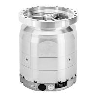
Edwards nEXT1230H Instruction Manual (137 pages)
Turbomolecular pumps
Brand:
Edwards
| Category:
Water Pump
| Size: 6 MB
Table of Contents
Table of Contents
4
Safety and Compliance
10
Definition of Warnings and Cautions
10
Safety Symbols
11
Trained Personnel
11
Important Safety Information
12
Mechanical Hazards
12
Electrical Hazards
13
Thermal Hazards
13
Danger through Materials and Substances
13
Dangers in Connection with Safety-Related Measures and Precautions
14
Overview
15
Ordering Information
15
Figure 1 Next Model Overview
16
Motor Controller
17
Operational Features
17
Power Limit Setting
18
Standby Speed
18
Timer
18
Analogue Output
18
Automatic Vent Options
19
Normal Speed Setting
19
Electronic Braking
20
Bearing Monitoring
20
Logic Interface
20
USB Interface
21
Parallel Control and Monitoring
21
Serial Control and Monitoring
21
Serial Control with Parallel Monitoring
22
Parallel Control with Serial Monitoring or Serial Configuration
22
CAN Interface
22
Motor Controller Configuration (Serial Configuration)
22
Technical Data
24
Operating and Storage Conditions
24
General Technical Data
24
Pumping Speed Curves
30
Figure 2 Pumping Speed Curves for Next730H
30
Figure 3 Pumping Speed Curves for Next730Q/730D
30
Figure 4 Pumping Speed Curves for Next930Q/930D
31
Figure 5 Pumping Speed Curves for Next1230H
31
Figure 6 Dimensional Drawing for Next730/930
32
Figure 7 Dimensional Drawing for Next1230H
33
Pumping Media
34
Vent Gas Specification and Vent Control Data
35
Materials Exposed to Gases Pumped
35
Figure 8 Maximum Allowed Rate of Pressure Rise During Venting: Pressure against Time
35
Purge Gas Specification
36
Water Cooling
36
Figure 9 Maximum Relative Humidity to Avoid Condensation with Water Cooling
37
Figure 10 Cooling Requirements for Nitrogen for Next730H
38
Figure 11 Cooling Requirements for Argon for Next730H
38
Figure 12 Cooling Requirements for Nitrogen for Next730Q/930Q
39
Figure 13 Cooling Requirements for Argon for Next730Q/930Q
39
Figure 14 Cooling Requirements for Nitrogen for Next730D/930D
40
Figure 15 Cooling Requirements for Argon for Next730D/930D
40
Electrical Data
41
Figure 16 Cooling Requirements for Nitrogen for Next1230H
41
Figure 17 Cooling Requirements for Argon for Next1230H
41
Logic Interface Connector
42
Serial Protocol
44
Figure 18 Interface Circuits for Next Turbo Pump Controllers
44
Command Set
46
Multi-Drop Operation
53
Figure 19 Conceptual Diagram for Multi-Drop Connection Using RS232 Interface
53
Motor Controller Auxiliary Connector Socket
54
Figure 20 RS485 Multi-Drop Connection
54
Indicator Leds
55
Figure 21 Valve Connector
55
Installation
57
Unpack and Inspect
57
Connect to the Vacuum System
58
Figure 22 Typical Pumping System with a Next Pump
58
Remove and Replace the Inlet Screen
59
Figure 23 Connections and Controls
59
Mounting Orientation
60
Figure 24 Mounting Orientation for Next1230H
60
Figure 25 Mounting Orientation for Next1230H INV
60
Mount the Pump
61
Figure 26 Mounting High Vacuum ISO-F Flange Connection with Clearance Hole
63
Figure 27 Mounting High Vacuum ISO-F Flange Connection with Blind Hole Thread
64
Figure 28 Mounting High Vacuum Flange ISO-K Flange at ISO-F Flange with Collar Flange
65
Figure 29 Mounting High Vacuum Flange ISO-K Flange at ISO-K Flange
66
Figure 30 Mounting High Vacuum Flange ISO-K Flange at ISO-F Flange with Claws
67
Figure 31 Mounting High Vacuum CF Flange Connection with Clearance Hole
68
Backing Port Connection
69
Figure 32 Mounting High Vacuum CF Flange Connection with Blind Hole Thread
69
Purge Gas Connection
70
Recommended Purge Gas Flow
70
Connect the Purge Gas
70
Electrical Installation
70
Earth (Ground) Connections
71
TIC or TAG Logic Interface Connections
71
Connect the Logic Interface to Control Equipment
71
Figure 33 Controller View
71
Connect the Electrical Supply
72
Connect the Parallel Control and Monitoring
73
Figure 34 Power Supply Connector
73
Connection for Serial Control and Monitoring
74
Figure 35 Logic Interface Connections - Parallel Control
74
Figure 36 Simplified Logic Interface Connections - Parallel Control
74
Connect the Serial Interface to the Customer Control Equipment
75
Serial Enable
76
Figure 37 Logic Interface Connections - RS232 Serial Control
76
Figure 38 Logic Interface Connections - RS485 Serial Control
76
Connection for Mixed Parallel and Serial Operation
77
Cooling
78
Cooling Requirements
78
Figure 39 Logic Interface Connection - Mixed Parallel and Serial Operation
78
Forced Air Cooling
79
Water Cooling
79
Configuration
81
Configure the Pump Using Serial Commands
81
Message Structure
82
Command and Reply Table Definitions
82
Power Limit Setting
83
Powering a Fan from the Motor Controller
84
Controlled Venting Options
84
Standby Speed Setting
85
Normal Speed Setting
85
Timer Setting and Options
86
Analogue Signal Options
87
Electronic Braking Options
87
Factory Settings
88
Assigning a Multi-Drop Address
88
Configure the Pump Using a TIC
89
Operation
90
Before Starting the Pump
90
Close the Vent Valve
90
Pre-Start Sequence
90
Vent Options, Vent Valve Connection and Control
91
Manual Vent Valve
91
TAV5 or TAV6 Solenoid Vent Valve
91
Vent Valve Control
92
Alternative Valve Connected to the Vacuum System
94
Operation with Parallel Control and Monitoring
94
Start the Pump with Parallel Control
94
Run the Pump at Standby Speed with Parallel Control
94
Stop the Pump with Parallel Monitoring
95
Parallel Monitoring
95
Operation with Serial Control and Monitoring
95
Delayed Start with Serial Control
95
Start the Pump with Serial Control
96
Run the Pump at Standby Speed with Serial Control
96
Stop the Pump with Serial Control
97
Monitor Temperature Readings with Serial Control
97
Monitor Link Parameter Readings with Serial Control
97
Monitor Measured Motor Speed with Serial Control
97
Mixed Parallel and Serial Operation
98
Operation with a TIC or TAG
99
Decelerating and Venting
99
Operation at Extreme Conditions
100
Operation with High Inlet Pressure
100
Operation at High Temperatures
100
Protection against Over-Speed
101
Electrical Supply Failure
101
Bakeout
102
Shut down the Pump Manually
103
Maintenance
104
Bearing Maintenance
104
Rotor Life
105
Cleaning the Pump
105
Decoding Service Status Words
105
Controller Run Time
107
Pump Run Time
107
Pump Cycles
107
Bearing Run Time
108
Storage
109
Disposal
110
Fault Finding
111
Command Set Error Codes
114
Flashing Service Codes
115
Flashing Error Codes
115
Flashing Inactivity Service Codes (Blue Bearing LED)
116
Decoding System Status Words
117
Service Information
119
Service
120
Return the Equipment or Components for Service
120
Bearing Monitoring and Conditioning System
121
Bearing On-Site Maintenance
121
Bearing Run in Mode
122
Service Counter Reset
122
Spares
123
Inlet Screen
123
Inlet Flange Seals and Integrated Inlet Screens
123
Accessories
124
Air Cooler
124
Water Cooler
125
Flange Heater
125
TAV5 and TAV6 Vent Valves
125
VRX Vent Restrictor
126
Vent Port Adaptor
126
PRX Purge Restrictor
126
Interface Cable
127
Nst2 PC Program
127
Auxiliary Connector
127
Auxiliary Extension Cable
127
Auxiliary 'Y' Cable Adaptor
128
EPS 800 Power Supply
128
Advertisement
Edwards nEXT1230H Instruction Manual (120 pages)
Turbomolecular pumps
Brand:
Edwards
| Category:
Water Pump
| Size: 2 MB
Table of Contents
Table of Contents
3
Safety and Compliance
8
Definition of Warnings and Cautions
8
Safety Symbols
9
Trained Personnel
9
Important Safety Information
10
Mechanical Hazards
10
Electrical Hazards
11
Thermal Hazards
11
Danger through Materials and Substances
11
Dangers in Connection with Safety-Related Measures and Precautions
12
Overview
13
Ordering Information
13
Figure 1 Next Model Overview
14
Motor Controller
14
Operational Features
15
Power Limit Setting
15
Standby Speed
16
Timer
16
Analogue Output
16
Automatic Vent Options
17
Normal Speed Setting
17
Electronic Braking
17
Bearing Monitoring
18
Logic Interface
18
Serial Control and Monitoring
19
USB Interface
19
Parallel Control and Monitoring
19
Serial Control with Parallel Monitoring
20
Parallel Control with Serial Monitoring or Serial Configuration
20
CAN Interface
20
Motor Controller Configuration (Serial Configuration)
20
Technical Data
22
Operating and Storage Conditions
22
General Technical Data
22
Pumping Speed Curves
25
Figure 2 Pumping Speed Curves for Next730D
25
Figure 3 Pumping Speed Curves for Next930D
26
Figure 4 Pumping Speed Curves for Next1230H
26
Figure 5 Dimensional Drawing for Next730-930D
27
Figure 6 Dimensional Drawing for Next1230H
28
Pumping Media
29
Vent Gas Specification and Vent Control Data
30
Materials Exposed to Gases Pumped
30
Figure 7 Maximum Allowed Rate of Pressure Rise During Venting: Pressure against Time
30
Purge Gas Specification
31
Water Cooling
31
Figure 8 Maximum Relative Humidity to Avoid Condensation with Water Cooling
32
Figure 9 Cooling Requirements for Next730D/930D
33
Electrical Data
34
Figure 10 Cooling Requirements for Next1230H
34
Logic Interface Connector
35
Serial Protocol
37
Figure 11 Interface Circuits for Next Turbo Pump Controllers
37
Command Set
39
Multi-Drop Operation
46
Figure 12 Conceptual Diagram for Multi-Drop Connection Using RS232 Interface
46
Motor Controller Auxiliary Connector Socket
47
Figure 13 RS485 Multi-Drop Connection
47
Indicator Leds
48
Figure 14 Valve Connector
48
Installation
50
Unpack and Inspect
50
Figure 15 Typical Pumping System with a Next Pump
51
Connect to the Vacuum System
51
Remove and Replace the Inlet Screen
52
Figure 16 Connections and Controls
52
Mounting Orientation
53
Figure 17 Mounting Orientation for Next1230H
53
Figure 18 Mounting Orientation for Next1230H INV
53
Mount the Pump
54
Backing Port Connection
55
Purge Gas Connection
55
Recommended Purge Gas Flow
55
Connect the Purge Gas
55
Electrical Installation
55
Figure 19 Controller View
56
TIC or TAG Logic Interface Connections
56
Earth (Ground) Connections
56
Connect the Logic Interface to Control Equipment
57
Connect the Electrical Supply
57
Connect the Parallel Control and Monitoring
58
Figure 20 Power Supply Connector
58
Connection for Serial Control and Monitoring
59
Figure 21 Logic Interface Connections - Parallel Control
59
Figure 22 Simplified Logic Interface Connections - Parallel Control
59
Connect the Serial Interface to the Customer Control Equipment
60
Serial Enable
61
Figure 23 Logic Interface Connections - RS232 Serial Control
61
Figure 24 Logic Interface Connections - RS485 Serial Control
61
Connection for Mixed Parallel and Serial Operation
62
Cooling
63
Cooling Requirements
63
Figure 25 Logic Interface Connection - Mixed Parallel and Serial Operation
63
Forced Air Cooling
64
Water Cooling
64
Figure 26 Attaching the Water Cooling
64
Configuration
66
Configure the Pump Using Serial Commands
66
Message Structure
67
Command and Reply Table Definitions
67
Power Limit Setting
68
Controlled Venting Options
69
Powering a Fan from the Motor Controller
69
Standby Speed Setting
70
Normal Speed Setting
70
Timer Setting and Options
71
Analogue Signal Options
72
Electronic Braking Options
72
Factory Settings
73
Assigning a Multi-Drop Address
73
Configure the Pump Using a Tic
74
Before Starting the Pump
75
Close the Vent Valve
75
Operation
75
Pre-Start Sequence
75
Manual Vent Valve
76
TAV5 or TAV6 Solenoid Vent Valve
76
Vent Options, Vent Valve Connection and Control
76
Vent Valve Control
77
Alternative Valve Connected to the Vacuum System
79
Operation with Parallel Control and Monitoring
79
Start the Pump with Parallel Control
79
Command
80
Delayed Start with Serial Control
80
Operation with Serial Control and Monitoring
80
Parallel Monitoring
80
Reply Sp Cr
80
Run the Pump at Standby Speed with Parallel Control
80
Stop the Pump with Parallel Monitoring
80
Run the Pump at Standby Speed with Serial Control
81
Start the Pump with Serial Control
81
Command Sp Cr
82
Monitor Link Parameter Readings with Serial Control
82
Monitor Measured Motor Speed with Serial Control
82
Monitor Temperature Readings with Serial Control
82
Reply
82
Reply Sp D Cr
82
Stop the Pump with Serial Control
82
Mixed Parallel and Serial Operation
83
Note
83
Decelerating and Venting
84
Figure 27 Serial and Parallel Control Flowchart
84
Operation with a TIC or TAG
84
Operation at Extreme Conditions
85
Operation at High Temperatures
85
Operation with High Inlet Pressure
85
Electrical Supply Failure
86
Protection against Over-Speed
86
Bakeout
87
Shut down the Pump Manually
88
Bearing Maintenance
89
Maintenance
89
Cleaning the Pump
90
Decoding Service Status Words
90
Rotor Life
90
Controller Run Time
92
Pump Cycles
92
Pump Run Time
92
Bearing Run Time
93
Storage
94
Disposal
95
Fault Finding
96
The Green Normal LED Does Not Light or the Pump Is Not Rotating at Full Speed or the Pump Fails Whilst Running
97
The Pump Does Not Respond in Multi- Drop Mode
97
Ultimate Pressure Cannot be Reached
97
Fail Signal or Standby Signal Not Working
98
No Serial Comms
98
The Pump Is very Noisy or There Is Excessive Vibration or both
98
Any Other Problems
99
Blue Bearing LED Is Flashing a Repeated Sequence
99
Blue Bearing LED Is Lit
99
Cause
99
Command Set Error Codes
99
Fault
99
Pump Is Not Accelerating to Full Speed
99
The Red Alarm LED Is Flashing
99
The Red Alarm LED Is on
99
Yellow Service LED Is Flashing a Repeated Sequence
99
Flashing Error Codes
100
Flashing Service Codes
100
Flashing Inactivity Service Codes (Blue Bearing LED)
101
Decoding System Status Words
102
Service Information
104
Return the Equipment or Components for Service
105
Service
105
Bearing Monitoring and Conditioning System
106
Bearing On-Site Maintenance
106
Bearing Run in Mode
107
Service Counter Reset
107
Inlet Flange Seals and Integrated Inlet Screens
108
Inlet Screen
108
Spares
108
Accessories
109
Air Cooler
109
Flange Heater
110
TAV5 and TAV6 Vent Valves
110
Water Cooler
110
PRX Purge Restrictor
111
Vent Port Adaptor
111
VRX Vent Restrictor
111
Auxiliary Connector
112
Auxiliary Extension Cable
112
Interface Cable
112
Nst2 PC Program
112
Auxiliary 'Y' Cable Adaptor
113
EPS 800 Power Supply
113
Advertisement
Related Products
Edwards nEXT1230
Edwards nEXT series
Edwards nEXT400
Edwards nEXT400D
Edwards nEXT300D
Edwards nEXT400T
Edwards nEXT240D
Edwards nEXT200200
Edwards nEXT730D
Edwards nEXT930D
Edwards Categories
Water Pump
Control Unit
Industrial Equipment
Measuring Instruments
Controller
More Edwards Manuals
Login
Sign In
OR
Sign in with Facebook
Sign in with Google
Upload manual
Upload from disk
Upload from URL