Table of Contents
Advertisement
Quick Links
Description
nXDS6i
nXDS10i
nXDS15i
nXDS20i
nXDS6iC
nXDS10iC
nXDS15iC
nXDS20iC
nXDS6iR
nXDS10iR
nXDS15iR
nXDS20iR
Instruction Manual
nXDS Scroll Pump
A735-01-880
Issue C Original
Item Number
A735-01-983
A736-01-983
A737-01-983
A738-01-983
A735-02-983
A736-02-983
A737-02-983
A738-02-983
A735-03-983
A736-03-983
A737-03-983
A738-03-983
Advertisement
Table of Contents

Related Manuals for Edwards nXDS series


Summary of Contents for Edwards nXDS series
- Page 1 A735-01-880 Issue C Original Instruction Manual nXDS Scroll Pump Description Item Number nXDS6i A735-01-983 nXDS10i A736-01-983 nXDS15i A737-01-983 nXDS20i A738-01-983 nXDS6iC A735-02-983 nXDS10iC A736-02-983 nXDS15iC A737-02-983 nXDS20iC A738-02-983 nXDS6iR A735-03-983 nXDS10iR A736-03-983 nXDS15iR A737-03-983 nXDS20iR A738-03-983...
-
Page 2: Declaration Of Conformity
Declaration of Conformity Edwards Limited, Crawley Business Quarter, Manor Royal, Crawley, West Sussex, RH10 9LW, UK declare under our sole responsibility, as manufacturer and person within the EU authorised to assemble the technical file, that the product(s) nXDS6i scroll pump... - Page 3 P200-10-019 Issue C Material Declaration In accordance with the requirements of the Chinese regulatory requirement on the Management Methods for the Restriction of the Use of Hazardous Substances in Electrical and Electronic Products Order No. 32 (also known as ‘China RoHS2’) and SJ/T 11364 Marking for the Restricted Use of Hazardous Substances in Electronic and Electrical Products: Product Labels Product...
- Page 4 This page intentionally blank.
-
Page 5: Table Of Contents
Gas ballast control ..................... 26 Start up procedure ..................... 26 To achieve ultimate vacuum..................27 To pump condensable vapours ..................27 4.10 Shut down........................ 27 © Edwards Limited 2017. All rights reserved. Page i Edwards and the Edwards logo are trademarks of Edwards Limited. - Page 6 Exhaust and ballast valve kit ..................44 For return of equipment, complete the HS Forms at the end of this manual. Page ii © Edwards Limited 2017. All rights reserved. Edwards and the Edwards logo are trademarks of Edwards Limited.
- Page 7 Chemical resistance conversion kit ................... 42 Electrical cables ......................42 Pump-to-controller cables .....................42 Tip-seal kit........................ 43 Cooling fan........................ 43 Gas ballast knob ......................43 Silencer spares kit .......................43 © Edwards Limited 2017. All rights reserved. Page iii Edwards and the Edwards logo are trademarks of Edwards Limited.
- Page 8 Exhaust and ballast valve kit ..................44 Associated publications Publication title Publication number Vacuum Pump and Vacuum System Safety P400-40-100 nXDS Serial Comms Interface Instruction Manual A735-01-860 Page iv © Edwards Limited 2017. All rights reserved. Edwards and the Edwards logo are trademarks of Edwards Limited.
-
Page 9: Introduction
Introduction Scope of this manual This manual provides installation, operation and maintenance instructions for the Edwards nXDS series of scroll pump. The pump must be used as specified in this manual. Read this manual before installing and operating the pump. -
Page 10: Atex Directive Implication
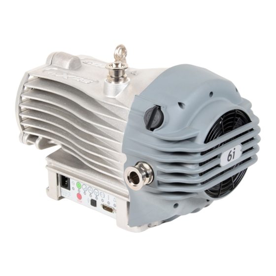
Do not allow air to enter the equipment. Ensure the system is leak tight. Further details can be obtained by contacting Edwards. Refer to the address page at the back of this instruction manual. General description The nXDS pump is shown in... -
Page 11: Logic Interface
For serial control either RS232 or RS485 can be selected. For Control Modes refer to Table For Logic interface data refer to Section 2.5. © Edwards Limited 2017. All rights reserved. Page 3 Edwards and the Edwards logo are trademarks of Edwards Limited. -
Page 12: Gas Ballast Control
Refer to Section Page 4 © Edwards Limited 2017. All rights reserved. Edwards and the Edwards logo are trademarks of Edwards Limited. -
Page 13: Quick Start Guide (Manual Control Mode)
The pump will re-start automatically after the power has BUTTON (>8 sec) function been restored. The pump is set to 30 Hz rotational full speed (factory default) © Edwards Limited 2017. All rights reserved. Page 5 Edwards and the Edwards logo are trademarks of Edwards Limited. - Page 14 Interface Note: Table 1 shows additional Edwards products, such as DX / nEXT Turbo pumps and active gauges that can be controlled at the same time using the various control methods displayed above. Page 6 © Edwards Limited 2017. All rights reserved.
-
Page 15: Technical Data
If the pump is operated outside the specified limits, then the pump housing may become hot; the controller may reduce the motor speed; and tip seal wear rate will be increased. © Edwards Limited 2017. All rights reserved. Page 7 Edwards and the Edwards logo are trademarks of Edwards Limited. -
Page 16: Pumping Media
The pump can be used to pump water vapour. Caution must be taken to ensure that vapour does not condense inside the pump. Refer to Section 4.6.1 on how to prevent condensation of water vapour in the pump. If pumping a vapour or gas not in the list above, contact Edwards for advice. 2.2.3 Performance characteristics The position of the gas ballast control defines the performance characteristics of the pump. -
Page 17: Nxds6I Performance Characteristics
A735-01-880 Issue C Figure 3 - nXDS6i Performance characteristics Figure 4 - nXDS10i Performance characteristics © Edwards Limited 2017. All rights reserved. Page 9 Edwards and the Edwards logo are trademarks of Edwards Limited. -
Page 18: Nxds15I Performance Characteristics
A735-01-880 Issue C Figure 5 - nXDS15i Performance characteristics Figure 6 - nXDS20i Performance characteristics Page 10 © Edwards Limited 2017. All rights reserved. Edwards and the Edwards logo are trademarks of Edwards Limited. -
Page 19: Mechanical Data
100 V 13 A, 250 V a.c. rms Note: Time-lag fuses should be used, as current transients can exceed the rated values. © Edwards Limited 2017. All rights reserved. Page 11 Edwards and the Edwards logo are trademarks of Edwards Limited. -
Page 20: Logic Interface Data
(Figure 1, item 7). The logic interface connector can be plugged directly into the Edwards 200W Turbo Instrument Controller (TIC) or turbo controller, or Turbo and Active Gauge controller (TAG). A suitable connector mating half must be used (not supplied) to connect the nXDS pump to the customer control system. Refer to... - Page 21 Connect to Pin 2 (0 V) to enable remote control via Parallel or Serial control modes. NORMAL – Status output Logic LOW when the pump rotational speed is at normal speed or above. © Edwards Limited 2017. All rights reserved. Page 13 Edwards and the Edwards logo are trademarks of Edwards Limited.
-
Page 22: Led Indicators
Indicates that a service interval has been reached. Refer to Service indicator Section 5.10. Alarm indicator Indicates an Alarm has been triggered. Refer to Section 5.11.6. Page 14 © Edwards Limited 2017. All rights reserved. Edwards and the Edwards logo are trademarks of Edwards Limited. -
Page 23: Installation
Ensure that the pump is suitable for the application. If in doubt, refer to the Edwards guidelines on vacuum pump and vacuum system safety (see associated publications at the end of the contents list at the front of this manual). -
Page 24: Installation Drawing
A735-01-880 Issue C Figure 8 - Installation drawing Note: All dimensions in mm. External dimensions are the same for all variants. Page 16 © Edwards Limited 2017. All rights reserved. Edwards and the Edwards logo are trademarks of Edwards Limited. -
Page 25: Unpack And Inspect
3.4.1 Mechanical fixing Note: The pump can be secured by using the four holes located on each corner of the pump base. Edwards recommends using M8 bolts. Connect to the vacuum system WARNING If pumping dangerous gases or vapours, connect the exhaust to a suitable treatment plant to prevent the discharge of dangerous gases and vapours to the surrounding atmosphere. -
Page 26: Electrical Installation
Ensure that the sealing surfaces are clean and scratch-free. Edwards recommends using an exhaust extraction system suitable for use with all process gases that will be pumped. Ensure that the exhaust extraction system cannot become blocked or obstructed when the pump is operating. -
Page 27: Electrical Supply Connection
IEC60320 connector. Edwards recommends fitting a separate earth to the pump using a non-insulated braid or a separate insulated green/ yellow conductor. The conductor must be a minimum of 14 AWG. Use the M5 x 10 screw and shake proof washer... - Page 28 A735-01-880 Issue C This page has been intentionally left blank. Page 20 © Edwards Limited 2017. All rights reserved. Edwards and the Edwards logo are trademarks of Edwards Limited.
-
Page 29: Operation
Manual operation The pump control functions of the user interface panel are detailed in Figure © Edwards Limited 2017. All rights reserved. Page 21 Edwards and the Edwards logo are trademarks of Edwards Limited. -
Page 30: Start And Stop
1%/sec. Once adjusted, the pump will return to this new user-defined speed each time standby speed is selected. The Standby button must be pressed to return to normal run speed. Page 22 © Edwards Limited 2017. All rights reserved. Edwards and the Edwards logo are trademarks of Edwards Limited. -
Page 31: Parallel Control And Monitoring
The output can be used to control other devices in the pumping system. The output can drive a low power relay of up to 24 V coil rating (up to 10 mA). © Edwards Limited 2017. All rights reserved. Page 23 Edwards and the Edwards logo are trademarks of Edwards Limited. -
Page 32: Analogue Speed Control
1. Start switch 2. Analogue control switch 3. nXDS pump logic interface ≡ Note: 0.1 V 1% of Default Run Speed Page 24 © Edwards Limited 2017. All rights reserved. Edwards and the Edwards logo are trademarks of Edwards Limited. -
Page 33: Hardware Configuration
The maximum running speed provided by the Analogue Speed control source is clamped by the maximum Standby Speed Setting, that is, 100% of the default run speed of 30 Hz. © Edwards Limited 2017. All rights reserved. Page 25 Edwards and the Edwards logo are trademarks of Edwards Limited. -
Page 34: Auto-Run
11, pin 3) in parallel control mode or a Start command in serial control mode. 5. Open the vacuum system isolation valve, if fitted. Page 26 © Edwards Limited 2017. All rights reserved. Edwards and the Edwards logo are trademarks of Edwards Limited. -
Page 35: To Achieve Ultimate Vacuum
4. Vent the nXDS pump system using the gas ballast control or the valve on the inlet. 5. Isolate the Mains supply. © Edwards Limited 2017. All rights reserved. Page 27 Edwards and the Edwards logo are trademarks of Edwards Limited. - Page 36 A735-01-880 Issue C This page has been intentionally left blank. Page 28 © Edwards Limited 2017. All rights reserved. Edwards and the Edwards logo are trademarks of Edwards Limited.
-
Page 37: Maintenance
In order to maintain the ATEX certification, all maintenance work has to be carried out in accordance with this nXDS instruction manual, the nXDS Replacement Tip Seal manual and the nXDS maintenance manual, using only genuine Edwards spare parts. WARNING Disconnect the pump and other components from the electrical supply to prevent accidental operation. -
Page 38: Maintenance Plan
The service indicator will flash to indicate that a tip-seal change may be required (based on typical tip-seal life). If after checking, the pump is no longer achieving the required performance, Edwards recommends carrying out a tip- seal replacement (refer to Section 5.10). -
Page 39: Replace The Tip-Seals
Edwards has developed a detailed maintenance manual and instructional video (Edwards part number A73501713) that will enable an experienced technician to undertake this work. If required Edwards can also provide face to face training. Please contact Edwards for more information or to purchase this training. -
Page 40: Service Indicator Codes
There is high pressure or a blockage in the exhaust line. The pump contains traces of process vapours; run 12 hours with gas ballast. Page 32 © Edwards Limited 2017. All rights reserved. Edwards and the Edwards logo are trademarks of Edwards Limited. -
Page 41: The Pump Has Poor Ultimate Vacuum
The cooling fan is not running. The process gas is too hot or the maximum continuous operating pressure has been exceeded. © Edwards Limited 2017. All rights reserved. Page 33 Edwards and the Edwards logo are trademarks of Edwards Limited. -
Page 42: Alarm Indicator Codes
In this case, try cycling the power. If cycling the power does not clear the indication, a software download may be required. In this situation, contact the supplier or Edwards. If the alarm indicator is flashing, identify the error flash code and consult Table There is a sufficient off period between each subsequent cycle repetition to clearly mark the start of a new flash sequence. - Page 43 If it does, contact the supplier or Edwards. sssssL Serial Control Mode Interlock. Re-activate serial enable and send a serial command to clear the error code. © Edwards Limited 2017. All rights reserved. Page 35 Edwards and the Edwards logo are trademarks of Edwards Limited.
- Page 44 A735-01-880 Issue C This page has been intentionally left blank. Page 36 © Edwards Limited 2017. All rights reserved. Edwards and the Edwards logo are trademarks of Edwards Limited.
-
Page 45: Storage And Disposal
Particular care must be taken with components which have been contaminated with dangerous process substances. Do not incinerate fluoroelastomer seals and O-rings. © Edwards Limited 2017. All rights reserved. Page 37 Edwards and the Edwards logo are trademarks of Edwards Limited. - Page 46 A735-01-880 Issue C This page has been intentionally left blank. Page 38 © Edwards Limited 2017. All rights reserved. Edwards and the Edwards logo are trademarks of Edwards Limited.
-
Page 47: Spares And Accessories
The majority of these centres employ Service Engineers who have undergone comprehensive Edwards training courses. Order spare parts and accessories from the nearest Edwards company or distributor. When ordering, state for each part required: Model and item number of your equipment ... -
Page 48: Accessories
2. Gas ballast adaptor 6. Vibration isolators 3a+b.Inlet/exhaust filter 7. Chemical resistance conversion kit 4. Silencer 8. Pump-to-controller cable (not shown) Page 40 © Edwards Limited 2017. All rights reserved. Edwards and the Edwards logo are trademarks of Edwards Limited. -
Page 49: Silencer
Table 20 - Inlet/exhaust filter Product description Ordering information Inlet/exhaust filter NW25/NW25 A505-97-805 © Edwards Limited 2017. All rights reserved. Page 41 Edwards and the Edwards logo are trademarks of Edwards Limited. -
Page 50: Exhaust Nozzle
Lead Assembly, 10 A, C13, No Plug A505-08-000 7.2.9 Pump-to-controller cable Use the control cable to control the nXDS pump using an Edwards Turbo Instrument Controller (TIC) or TIC Turbo Controller, or a (TAG) Active Gauge controller. Table 24 - Pump-to-controller cables Product description... -
Page 51: Spares
Replacement elements for the inlet/exhaust filter A505-97-805. Table 29 - Inlet/exhaust filter spares Product description Ordering information 5 micron element A505-97-802 1 micron element A505-97-803 © Edwards Limited 2017. All rights reserved. Page 43 Edwards and the Edwards logo are trademarks of Edwards Limited. -
Page 52: Bearing Replacement Kit (Not Field Serviceable)
Exhaust and ballast valve kit (C versions only) A735-01-804 Note: nXDS20i, nXDS20iR and nXDS20iC versions require two service kits per pump. Page 44 © Edwards Limited 2017. All rights reserved. Edwards and the Edwards logo are trademarks of Edwards Limited.
Need help?
Do you have a question about the nXDS series and is the answer not in the manual?
Questions and answers