
Related Manuals for Edwards nEXT300


Summary of Contents for Edwards nEXT300
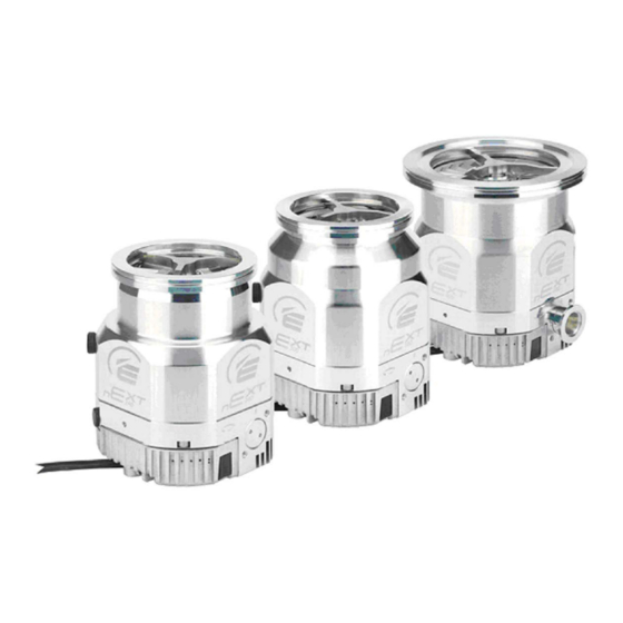
- Page 1 Turbomolecular Pumps nEXT240, nEXT300 and nEXT400 INSTRUCTION MANUAL edwardsvacuum.com B80000880_G Original instructions...
- Page 2 Copyright notice ©Edwards Limited 2022. All rights reserved. Trademark credit Edwards and the Edwards logo are trademarks of Edwards Limited, Innovation Drive, Burgess Hill, West Sussex RH15 9TW. Disclaimer The content of this manual may change from time to time without notice. We accept no liability for any errors that may appear in this manual nor do we make any expressed or implied warranties regarding the content.
-
Page 3: Table Of Contents
4.3.1 Inlet screen (installed on CF only)......39 B80000880_G Page 3 04/2022 - ©Edwards Limited... - Page 4 5.2 Configuring the nEXT pump using a TIC......68 B80000880_G Page 4 04/2022 - ©Edwards Limited...
- Page 5 8.10 Useful service information........91 B80000880_G Page 5 04/2022 - ©Edwards Limited...
- Page 6 13.11 TIC PC program..........103 B80000880_G Page 6 04/2022 - ©Edwards Limited...
- Page 7 Figure 3: nEXT300 performance curve........
-
Page 8: Safety And Compliance
Information about properties or instructions for an action which, if ignored, will cause damage to the equipment. We reserve the right to change the design and the stated data. The illustrations are not binding. Keep the instructions for future use. B80000880_G Page 8 04/2022 - ©Edwards Limited... -
Page 9: Safety Symbols
Earth point for radio equipment or antenna. 1.3 Trained personnel “Trained personnel” for the operation of this pump are ▪ skilled workers with knowledge in the fields of mechanics, electrical engineering and vacuum technology and B80000880_G Page 9 04/2022 - ©Edwards Limited... - Page 10 B80000880_G - Safety and compliance ▪ personnel specially trained for the operation of vacuum pumps. B80000880_G Page 10 04/2022 - ©Edwards Limited...
-
Page 11: Introduction
An 'iD' or 'iT' interstage variant gives an interstage port between the turbomolecular blades and drag mechanism. For SEM and TEM applications, an 'L' variant is available which offers lower vibration and stray magnetic field emissions. B80000880_G Page 11 04/2022 - ©Edwards Limited... -
Page 12: Pump Model Description
▪ The electronics constantly monitors the temperature in the controller and the temperature of the motor in the pump. If the controller or the motor gets too hot, B80000880_G Page 12 04/2022 - ©Edwards Limited... -
Page 13: Operational Features
In standby mode, the pump rotational speed is lower than the full rotational speed. The default setting for standby speed is 70% of the full speed. To operate the pump at standby speed, it must be in the start condition. B80000880_G Page 13 04/2022 - ©Edwards Limited... -
Page 14: Timer
The analogue output can monitor only one system parameter at a time. You can configure the controller to monitor different system parameter. Refer to Analogue signal options on page 67. B80000880_G Page 14 04/2022 - ©Edwards Limited... -
Page 15: Automatic Vent Options
You can plug the logic interface into the manufacturer's TIC Turbo Controller or TIC Turbo Instrument Controller and then use the given functionality. The logic interface can be connected to the customer control system as an alternative. B80000880_G Page 15 04/2022 - ©Edwards Limited... -
Page 16: Parallel Control And Monitoring
2.5.3 Serial control with parallel monitoring Normal and analogue signals stay available when using serial control. You can control the pump through the serial link while monitoring the normal and analogue signals in the parallel interface. B80000880_G Page 16 04/2022 - ©Edwards Limited... -
Page 17: Parallel Control With Serial Monitoring Or Serial Configuration
ASCII message protocol given in Connection for serial control and monitoring on page 47. The TIC PC program can save number of pump configurations which can be downloaded to the other pumps. B80000880_G Page 17 04/2022 - ©Edwards Limited... -
Page 18: Technical Data
Table: nEXT 240 pumps technical data, Table: nEXT 300 pumps technical da- Table: nEXT 400 pumps technical Performance data, Figure: nEXT240 performance curve, Figure: nEXT300 performance curve Figure: nEXT400 performance curve. Refer to Figure: nEXT 240 dimensions Dimensions (mm), Figure: nEXT 300 dimensions (mm) Figure: nEXT 400 dimensions (mm). - Page 19 >1 x 10 >1 x 10 >1 x 10 1 x 10 1 x 10 3 x 10 3 x 10 5 x 10 5 x 10 1 x 10 1 x 10 B80000880_G Page 19 04/2022 - ©Edwards Limited...
- Page 20 1 x 10 1 x 10 Interstage pumping speed 13 l/s 13 l/s 13 l/s 13 l/s 13 l/s 13 l/s 13 l/s 13 l/s 11 l/s 11 l/s 11 l/s 11 l/s B80000880_G Page 20 04/2022 - ©Edwards Limited...
- Page 21 Water cooling (40 °C Ambient) 4.75 mbar 2.75 mbar 6 mbar 3.75 mbar 6.5 mbar 4 mbar Force air cooling (35 °C Ambi- 3 mbar 1.5 mbar 6.5 mbar 7 mbar 6.5 mbar 8 mbar ent) B80000880_G Page 21 04/2022 - ©Edwards Limited...
-
Page 22: Figure 2 Next240 Performance Curve
57 for cooling conditions. At pressures above these, the rotational speed decreases below nominal. † Cooling water temperature 15 °C at a flow rate of 30 l hr Figure 2 nEXT240 performance curve B80000880_G Page 22 04/2022 - ©Edwards Limited... -
Page 23: Figure 3 Next300 Performance Curve
B80000880_G - Technical data Figure 3 nEXT300 performance curve Figure 4 nEXT400 performance curve B80000880_G Page 23 04/2022 - ©Edwards Limited... -
Page 24: Figure 5 Next 240 Dimensions (Mm)
10. Body purge port 10. Body purge port 11. Electrical drive unit 11. Electrical drive unit 12. Envelope vent port ⅛ inch BSP 12. Envelope vent port ⅛ inch BSP 13. Envelope vent 13. Envelope vent B80000880_G Page 24 04/2022 - ©Edwards Limited... -
Page 25: Figure 6 Next 300 Dimensions (Mm)
10. Body purge port 10. Body purge port 11. Electrical drive unit 11. Electrical drive unit 12. Envelope vent port ⅛ inch BSP 12. Envelope vent port ⅛ inch BSP 13. Envelope vent 13. Envelope vent B80000880_G Page 25 04/2022 - ©Edwards Limited... -
Page 26: Figure 7 Next 400 Dimensions (Mm)
10. Body purge port 10. Body purge port 11. Electrical drive unit 11. Electrical drive unit 12. Envelope vent port ⅛ inch BSP 12. Envelope vent port ⅛ inch BSP 13. Envelope vent 13. Envelope vent B80000880_G Page 26 04/2022 - ©Edwards Limited... -
Page 27: Operation And Storage Environment
> 15 seconds to reach 50% Refer to Figure: Maximum allowed rate Maximum permitted rate of increase of of increase in pressure during venting: pressure pressure against time (pump initially at full speed). B80000880_G Page 27 04/2022 - ©Edwards Limited... -
Page 28: Purge Gas Specification
Table 9 Cooling water specification Cooling water specification Reference data Mechanically clean and optically clear Quality with no deposits or turbidity B80000880_G Page 28 04/2022 - ©Edwards Limited... -
Page 29: Electrical Data
Risk of explosion. Do not use the nEXT pump to pump pyrophoric or explosive gas mixtures as the pump is not applicable for this purpose. The pump and its connections are not designed to contain an explosion. B80000880_G Page 29 04/2022 - ©Edwards Limited... - Page 30 The pump is not applicable for pumping aggressive or corrosive gases. The pump can be used to pump the oxygen and water vapour, with the conditions that follows: B80000880_G Page 30 04/2022 - ©Edwards Limited...
-
Page 31: Materials Exposed To Gases Pumped
Logic interface item Connector* 15‑way D‑type male nEXT pumps electrical supply: Permitted voltage range 24 ‑ 48 V d.c. +5%, -10% (21.6 to 50.4 V d.c.) (with ripple) Maximum voltage ripple 0.5 V r.m.s. B80000880_G Page 31 04/2022 - ©Edwards Limited... - Page 32 Figure: Interface circuits for nEXT tur- bo pump controllers. Fail Off (3.3 kW pull up to 12 V d.c.) On (< 0.1 V d.c. sinking 1.7 mA, < 0.8 V d.c. sinking 20 mA) B80000880_G Page 32 04/2022 - ©Edwards Limited...
- Page 33 NORMAL status output the pump is at normal speed or above the normal speed 8, 13, 14 Electrical supply: 0 V 1, 6, 11 Electrical supply: 24 V - Positive 48 V d.c. B80000880_G Page 33 04/2022 - ©Edwards Limited...
-
Page 34: Controller Connector Socket
3‑way controller connector is concealed with a black protective cover. Before you use the 3‑way controller connector, remove the black protective cover with the help of a screwdriver. The mating plug for the 3‑way controller connector is supplied with the pump. B80000880_G Page 34 04/2022 - ©Edwards Limited... -
Page 35: Indicator Led's
Table 13 Indicator LED’s Description The green LED stays when the rotational speed of the pump is more Normal LED than the normal speed setting, irrespective of the acceleration or de- celeration of the pump. B80000880_G Page 35 04/2022 - ©Edwards Limited... - Page 36 The error codes can be used for the fault finding as given in Fault find‐ on page 82. Note: If an external electrical load is connected to the normal output line, the Normal LED can come on. B80000880_G Page 36 04/2022 - ©Edwards Limited...
-
Page 37: Installation
If the pump is not to be used immediately, store the pump in conditions as given in Storage on page 93. Table 14 Checklist of components Quantity Description Check ( ü ) nEXT pump with inlet screen fitted (installed to CF pumps on- B80000880_G Page 37 04/2022 - ©Edwards Limited... -
Page 38: Typical Installation
Failure to do so can cause injury to people while installation. We recommend you to do a leak test of the system after the installation is completed. B80000880_G Page 38 04/2022 - ©Edwards Limited... -
Page 39: Inlet Screen (Installed On Cf Only)
CAUTION: INLET SCREEN Risk of damage to equipment. The inlet screen prevents the contamination of the pump. Do not remove the inlet screen until the pump is prepared to be mounted onto the system. B80000880_G Page 39 04/2022 - ©Edwards Limited... -
Page 40: Mechanical Fixing
If installation of the pump is not possible because of the nature of the vacuum system, install the base of the pump at a firm support. Refer to Base mounting page 42 for instructions on base mounting the pump. B80000880_G Page 40 04/2022 - ©Edwards Limited... -
Page 41: Inlet Connection And Orientation
Use all supplied bolts with the rotatable collar. ▪ If the pump has a VG flange, use all supplied bolts of 8 x M10 and washers to connect the pump to the vacuum system. Flange installation bolts must have B80000880_G Page 41 04/2022 - ©Edwards Limited... -
Page 42: Base Mounting
Pa). Lower backing pressures increases the evaporation rate of the lubrication oil and can decrease the life of the bearings. Note: Make sure that the ducting is done at the backing line if oil mist or hazardous substances are available. B80000880_G Page 42 04/2022 - ©Edwards Limited... -
Page 43: Interstage Connection (Variants Only)
Make sure that the electrical installation of the pump is in accordance with the regional and local codes and conforms to local and national safety requirements. The pump must be connected to an applicable power supply unit with an applicable earth (ground) point. B80000880_G Page 43 04/2022 - ©Edwards Limited... -
Page 44: Ground The Connections
Connection for serial control and monitoring on page 47. The logic interface gives the facility to work with a mixture of parallel and serial control. Refer to Connection for mixed parallel and serial operation on page 56. B80000880_G Page 44 04/2022 - ©Edwards Limited... -
Page 45: Connect The Electrical Supply
If there is no connection available between 0 V and ground, make the connection at the power supply. Other electrical equipment connected to the system can make a connection between 0 V and ground, for example a personal computer or a measuring equipment. B80000880_G Page 45 04/2022 - ©Edwards Limited... -
Page 46: Connect The Parallel Control And Monitoring
To stop the pump, remove the connection between the pin 3 and pin 2. To put the pump in standby, connect the pin 4 (Standby) and pin 3 (Start / Stop) to pin 2 (0 V reference). B80000880_G Page 46 04/2022 - ©Edwards Limited... -
Page 47: Connection For Serial Control And Monitoring
Move the switch to the right to enable RS232 serial interface. Move the switch to the left to enable RS485 serial interface. The default setting of the motor controller is RS232 serial interface. B80000880_G Page 47 04/2022 - ©Edwards Limited... -
Page 48: Figure 14 Controller Status Information
When the RS232 option is selected, more hardware is necessary to link number of pump units to a single serial link master. A concept drawing of one possible arrangement is shown in Figure: Conceptual diagram for multi‐drop connection using B80000880_G Page 48 04/2022 - ©Edwards Limited... -
Page 49: Serial Enable
Serial enable operates as an interlock for the start commands sent over the serial interface. If the pump operates in serial control mode (having been sent a serial start command) and the serial enable becomes inactive, the pump will trigger a fail condition B80000880_G Page 49 04/2022 - ©Edwards Limited... -
Page 50: Serial Protocol
Refer to Multi‐drop operation on page 55 for more information about how to operate the pumps in the multi‑drop mode. B80000880_G Page 50 04/2022 - ©Edwards Limited... -
Page 51: Figure 17 Conceptual Diagram For Multi-Drop Connection Using Rs232 Interface
Figure 17 Conceptual diagram for multi-drop connection using RS232 interface 1. RS232 interface on control equipment 1. RS232 interface on control equipment 2. Buffer 2. Buffer 3. pump 3. pump 4. OR gate 4. OR gate B80000880_G Page 51 04/2022 - ©Edwards Limited... -
Page 52: Message Structure
4.7.5 Command set Refer to Table: Summary of commands that can be sent to the nEXT pump for the summary of the full set of commands available to control and monitor the pump. B80000880_G Page 52 04/2022 - ©Edwards Limited... - Page 53 ?S854 low 50% Power limit !S855 50.200 decimal Watts Link power maximum setting ?S855 Normal !S856 50.100 decimal Normal speed as a percentage speed setting of full speed ?S856 B80000880_G Page 53 04/2022 - ©Edwards Limited...
- Page 54 Hours run by pump time 0..999999 decimal hours Hours until pump service due Pump cycles ?V884 0..65535 decimal cycles Cycles run by pump 0..65535 decimal cycles Cycles until pump service due B80000880_G Page 54 04/2022 - ©Edwards Limited...
-
Page 55: Multi-Drop Operation
Each pump must be assigned its own individual address before it can be installed in a multi‑drop system. The command to assign the multi‑drop address is sent in standard nEXT message format. Refer to Assigning a multi‐drop address on page 67. B80000880_G Page 55 04/2022 - ©Edwards Limited... -
Page 56: Connection For Mixed Parallel And Serial Operation
To stop the pump, use the parallel stop switch. The serial interface accepts the start or stop commands only when you use the parallel interface switch to stop the pump. B80000880_G Page 56 04/2022 - ©Edwards Limited... -
Page 57: Vent Options, Vent Valve Connection And Control
Maximum allowed rate of increase in pressure during venting: pressure against time (pump initially at full speed)) or open the vent valve only after the pump speed has decreased to 50% of the full rotational speed. B80000880_G Page 57 04/2022 - ©Edwards Limited... -
Page 58: Manual Vent Valve
Refer to Figure: Maximum allowed rate of increase in pressure during venting: pressure against time (pump initially at full speed). B80000880_G Page 58 04/2022 - ©Edwards Limited... -
Page 59: Vent Valve Control
Before the controller operates (shuts) the TAV solenoid valve, the valve will be in the 'open' vent state. If the vacuum system is a large system, let backing pump decrease the pressure in the system to an acceptable level before you start the pump. B80000880_G Page 59 04/2022 - ©Edwards Limited... -
Page 60: Alternative Valve Connected To The Vacuum System
Forced air cooling: The ambient air temperature must be 5 °C to 35 °C when you use the forced air cooling. make sure that there is sufficient supply of cooling air to the pump. B80000880_G Page 60 04/2022 - ©Edwards Limited... -
Page 61: Forced Air Cooling
Push the nylon hose (approximately 10 mm outer diameter) into the ends of the hose connectors of the water cooler at the pump. You can also remove the hose B80000880_G Page 61 04/2022 - ©Edwards Limited... -
Page 62: Figure 20 Maximum Relative Humidity To Avoid Condensation With Water Cooling
To prevent the breaking of the cooling water circuit when you remove the pump for the maintenance, remove the two M6 screws. Remove the water cooler from the pump. Figure 20 Maximum relative humidity to avoid condensation with water cooling B80000880_G Page 62 04/2022 - ©Edwards Limited... -
Page 63: Configuration
200 W 50 W 160 W* * This is the most common settings. Some specific customer pump options may have a different value. Refer to Pump model description on page 12 for details. B80000880_G Page 63 04/2022 - ©Edwards Limited... -
Page 64: Power Supply To The Fan From The Controller
To set a vent option, send the command that follows, (character 'd' refers to the option number shown in Table: Vent options): Command The reply as follows: Reply The venting option is now stored in the memory of the pump. B80000880_G Page 64 04/2022 - ©Edwards Limited... -
Page 65: Standby Speed Setting
Command The reply is as follows: Reply The normal speed is now stored in the memory of the pump. To check what normal speed is set, send a query as follows: B80000880_G Page 65 04/2022 - ©Edwards Limited... -
Page 66: Timer Setting And Options
The reply will be as follows: Reply To check if the timer is enabled or disabled, send the query that follows: Command The reply will be as follows (where d=0 means disabled and d=1 means enabled): Reply B80000880_G Page 66 04/2022 - ©Edwards Limited... -
Page 67: Analogue Signal Options
When the pump is shipped, multi-drop mode is disabled by default. To assign a multi‑drop address, send the command that follows (where the 'd' characters represent the address): B80000880_G Page 67 04/2022 - ©Edwards Limited... -
Page 68: Configuring The Next Pump Using A Tic
The parameters of the pump that can be set using the TIC are: ▪ Power limit setting ▪ Controlled venting options, including operating a fan from the controller ▪ Standby speed setting B80000880_G Page 68 04/2022 - ©Edwards Limited... - Page 69 ▪ configuration of the analogue output options ▪ assignment of a multi‑drop address. Refer to the TIC PC program Instruction Manual for more information. B80000880_G Page 69 04/2022 - ©Edwards Limited...
-
Page 70: Operation
0.5 seconds and then extinguish. Refer to Fault finding on page 82 if: ▪ LEDs does not illuminate ▪ Red or yellow LEDs flashes in a repeated sequence ▪ Red LED is illuminated. B80000880_G Page 70 04/2022 - ©Edwards Limited... -
Page 71: Operation With Parallel Control And Monitoring
This allows the backing pump to decrease the pressure in the vacuum system. To close the vent valve, send the command that follows: Command The reply is as follows: Reply B80000880_G Page 71 04/2022 - ©Edwards Limited... -
Page 72: Start The Pump
When the stop command is received, the pump rotor will decelerate and stop. To stop the pump, send the command (over the serial communications link) that follows: Command The reply is as follows: Reply B80000880_G Page 72 04/2022 - ©Edwards Limited... -
Page 73: Temperature Readings
The second return number is a 32‑bit system status word (set of 8 hexadecimal characters) which is useful for fault finding. Refer to Decoding system status words page 89 to decode the system status word. B80000880_G Page 73 04/2022 - ©Edwards Limited... -
Page 74: Mixed Parallel And Serial Operation
This interlock function only operates with serial start commands and in serial control mode only. In serial control mode, the pump cannot be commanded to standby speed by the standby line, instead a serial standby command must be used. B80000880_G Page 74 04/2022 - ©Edwards Limited... -
Page 75: Operation With A Tic
50%, otherwise the rate of increase in pressure can be too high, which can damage the pump. In an emergency, open the vent valve quickly to decelerate the pump rotor in the shortest possible time. B80000880_G Page 75 04/2022 - ©Edwards Limited... -
Page 76: Operation At Extreme Conditions
The motor controller signals a fail condition if over‑speed is detected. If the pump is operating at over‑speed, set the pump to off and contact us or the supplier. B80000880_G Page 76 04/2022 - ©Edwards Limited... -
Page 77: Electrical Supply Failure
Use the pumps with CF flanges for bakeout. When baking the pump to more than 70 °C at the inlet flange, the pump must be water cooled to prevent the damage to the bearing lubricant. B80000880_G Page 77 04/2022 - ©Edwards Limited... - Page 78 Parallel or serial control mode power failure. The pump will creases below 50% speed up to designated speed af- ter the power has been restored. B80000880_G Page 78 04/2022 - ©Edwards Limited...
- Page 79 The fail signals caused during the regen- erative power period are lost when the power is restored. B80000880_G Page 79 04/2022 - ©Edwards Limited...
-
Page 80: Maintenance
As a precautionary measure, we recommend you to return the pumps for a major service (rotor replacement) after 20,000 cycles of acceleration to full speed and back to a stop, or after ten years of use, whichever occurs first. B80000880_G Page 80 04/2022 - ©Edwards Limited... -
Page 81: Clean The External Surfaces Of The Pump
Only small amount of a cleaning solution is necessary to clean the pump surface. For environmental reasons, keep wastage of cleaning solutions and solvents to a minimum. B80000880_G Page 81 04/2022 - ©Edwards Limited... -
Page 82: Fault Finding
If there is a fail signal, check if the red alarm LED is flashing. If yes, refer to Flashing error codes on page 88. If the power is supplied and fail signal is not given, but the rotor does not rotate, the fault is in the pump. B80000880_G Page 82 04/2022 - ©Edwards Limited... - Page 83 The backing pressure is more than 10 mbar (1x10 Pa). Remedy The backing pressure can be too high. Check for backing pipeline leaks. If the throughput is high, a larger backing pump can be necessary. B80000880_G Page 83 04/2022 - ©Edwards Limited...
- Page 84 ▪ Left for RS485, right for RS232. ▪ Right for parallel control and monitoring. Cause Incorrect baud rate and node address. Remedy Check baud rate and, if operating in multi-drop mode, the node address matches those of the pump. B80000880_G Page 84 04/2022 - ©Edwards Limited...
-
Page 85: Flashing Service Codes
When a service is necessary, the standard once per revolution flash on the yellow status LED is changed to a service flash code. Refer to Table: Flashing service codes for the service flash codes. B80000880_G Page 85 04/2022 - ©Edwards Limited... -
Page 86: Decoding Service Status Words
Set when hours until pump service due = 0 Pump service due or cycles until pump service due = 0 Set when hours until controller service due = Controller service due Reserved Reserved B80000880_G Page 86 04/2022 - ©Edwards Limited... -
Page 87: Controller Run Time
Send the query that follows: Command The reply is as follows (where, first number is the start-stop cycles completed by the pump and second is the number of start-stop cycles until service is recommended): B80000880_G Page 87 04/2022 - ©Edwards Limited... -
Page 88: Bearing Run Time
Timer disa- high. bled. Restart the system. If the er- Controller internal software Lsssss ror code is not cleared, con- mismatch tact us or the supplier. B80000880_G Page 88 04/2022 - ©Edwards Limited... -
Page 89: Decoding System Status Words
0 0 1 0 0 0 1 0 1 0 0 0 0 0 1 1 0 0 0 0 0 0 0 0 0 0 1 0 0 0 1 0 Refer to Table: Hexadecimal conversion table for more information. Table 28 Hexadecimal conversion table Hexadecimal Binary Decimal 0000 B80000880_G Page 89 04/2022 - ©Edwards Limited... - Page 90 Start command active Serial enable Serial enable active Standby Standby active Half full speed Above 50% full rotational speed Parallel control mode Exclusive control mode selection Serial control mode Exclusive control mode selection B80000880_G Page 90 04/2022 - ©Edwards Limited...
-
Page 91: Useful Service Information
This information is useful for the service personnel to select the model of the pump. Send the query that follows to find out the pump type: B80000880_G Page 91 04/2022 - ©Edwards Limited... - Page 92 String 3 Send the query that follows to find out the boot loader software version: Command The reply is as follows (where, string 1 is the boot loader software version number): Reply String 1 B80000880_G Page 92 04/2022 - ©Edwards Limited...
-
Page 93: Storage
When necessary, prepare and install the pump as given in Installation on page 37. Always keep the pump upright to prevent the drainage of oil from the bearing reservoir. B80000880_G Page 93 04/2022 - ©Edwards Limited... -
Page 94: Disposal
Do not the inhale the particulates which can be in the pump. Do not incinerate the pump. The pump contains phenolic and fluorosilicone materials that can decompose to very dangerous substances when heated to high temperatures. B80000880_G Page 94 04/2022 - ©Edwards Limited... -
Page 95: Service
HS1, fill in the electronic HS2 form, print it, sign it, and return the signed copy to us. NOTICE: If we do not receive a completed HS2 form, your equipment cannot be serviced. B80000880_G Page 95 04/2022 - ©Edwards Limited... -
Page 96: Bearing And Oil Cartridge On-Site Maintenance
Bearing tool kit B80000805 Table 32 Service kits Service kit Item number Oil cartridge B80000811 Bearing and oil cartridge B80000810 Note: The oil cartridge and bearing tool kits are necessary when changing a pump bearing. B80000880_G Page 96 04/2022 - ©Edwards Limited... -
Page 97: Spares
Inlet flange seal Item number DN100ISO‑K ISO100 trapped O‑ring with integrated coarse inlet B81000808 screen DN100ISO‑K ISO100 trapped O‑ring with integrated fine inlet B81000809 screen DN160ISO‑K ISO160 trapped O‑ring with integrated coarse inlet B80000825 screen B80000880_G Page 97 04/2022 - ©Edwards Limited... -
Page 98: Nw16 And Nw25 Ports
12.4 NW16 and NW25 Ports The pumps are supplied with NW25 exhaust and booster ports. The item numbers of replacement ports are as follows. Table 36 NW16 and NW25 ports Port Item Number NW25 B80000809 NW16 B80000806 B80000880_G Page 98 04/2022 - ©Edwards Limited... -
Page 99: Accessories
1. BX 250 bake out band (DN100CF 2. BX 250 bake out band position 2. BX 250 bake out band position envelope shown) envelope shown) 3. WCX water cooling accessory 3. WCX water cooling accessory B80000880_G Page 99 04/2022 - ©Edwards Limited... -
Page 100: Acx Air Cooler
ACX nEXT radial fan 135 mA B58053175 ACX nEXT axial fan 135 mA B58053185 ACX nEXT radial fan (with Phoenix connec- 135 mA B58053170 tor) ACX nEXT axial fan (with Phoenix connec- 135 mA B58053180 tor) B80000880_G Page 100 04/2022 - ©Edwards Limited... -
Page 101: Wcx Water Cooler
Use a VRX installed orifice vent restrictor to restrict flow of vent gas into the pump. A VRX vent restrictor can be installed to the inlet of a TAV5 or TAV6 vent valve or to a PRX10 purge restrictor. Refer to Table: Vent restrictor orifice diameter (with atmospheric B80000880_G Page 101 04/2022 - ©Edwards Limited... -
Page 102: Vent Port Adaptor
The tool kit and parts that follows are available. Table 44 C-clamp adaptor tool kit Tool kit Item Number Port removal and insertion tool B80000807 Table 45 C-clamp adaptor port kit Port kit Item Number C‑clamp and NW25 flange adaptor B80000813 B80000880_G Page 102 04/2022 - ©Edwards Limited... -
Page 103: Interface Cable
The TIC PC program is a PC‑based software that can be used to retrieve and set the user configurable parameters in the pump. TIC PC program enables monitoring and data logging of the pumping system. B80000880_G Page 103 04/2022 - ©Edwards Limited... - Page 104 Czech Republic RH15 9TW T: +42(0) 580 582 728 documentation@edwardsvacuum.com The products specified and listed below • nEXT Turbo Molecular Pump B81XXXXXX nEXT240 variants B82XXXXXX nEXT300 variants B83XXXXXX nEXT400 variants B84XXXXXX nEXT200100 variants B85XXXXXX nEXT200200 variants B86XXXXXX nEXT240 variants B87XXXXXX...
- Page 105 You must retain the signed legal declaration for future reference This declaration becomes invalid if modifications are made to the product without prior agreement. Signed for and on behalf of Edwards Ltd Petr Šmérek – Engineering Manager Jan Večeřa – General Manager Scientific Vacuum Division, Lutín, CZ...
- Page 106 ADDITIONAL LEGISLATION AND COMPLIANCE INFORMATION EMC (EU, UK): Class B Industrial equipment Caution: This equipment is not intended for use in residential environments and may not provide adequate protection to radio reception in such environments. RoHS (EU, UK): Material Exemption Information This product is compliant with no Exemptions REACH (EU, UK) This product is a complex article which is not designed for intentional substance release.
- Page 107 This page has been intentionally left blank.
- Page 108 edwardsvacuum.com...
Need help?
Do you have a question about the nEXT300 and is the answer not in the manual?
Questions and answers