Veripos LD6 Operation Manual
Version 8 & version 50
Hide thumbs
Also See for LD6:
- Installation manual (62 pages) ,
- Operation manual (88 pages) ,
- Quick manual (2 pages)
Table of Contents
Advertisement
Quick Links
Advertisement
Table of Contents

Related Manuals for Veripos LD6


Summary of Contents for Veripos LD6
- Page 1 LD6 Operation Manual Version 8 & Version 50 VERIPOS...
-
Page 2: Table Of Contents
NMEA ..................45 2.10 A ....................46 CTIONS 2.10.1 Log off ..................46 2.10.2 Reboot ..................46 2.10.3 Shutdown ................46 2.10.4 Factory Reset ................. 46 2.10.5 Display Config ................ 47 LD6 Operation Manual (Version 8 & Version 50) 2(85) - Page 3 OVERAGE LD6 M ................72 ENU STRUCTURE ..................77 SER BEAM NMEA S ................. 79 ENTENCES CONTACT INFORMATION ............... 86 VERIPOS H ................86 ELPDESK VERIPOS O ..............86 FFICE OCATIONS LD6 Operation Manual (Version 8 & Version 50) 3(85)
-
Page 4: Introduction
00520). Throughout this manual reference will be made to the VERIPOS Helpdesk. The Helpdesk is provided by VERIPOS and the first point of contact for technical enquiries and assistance. It is manned 24 hours per day, 365 days per year. -
Page 5: Terms And Abbreviations
Veripos Single Frequency DGPS System Space Vehicle Ultra Veripos PPP GNSS Service Universal Serial Bus Coordinated Universal Time VDOP Vertical Dilution of Precision VERIPOS Global DGPS service provider VOSS VERIPOS Online Support System LD6 (Version 8 & Version 50) Operations Manual 4(85) - Page 6 Introduction Watt WAAS Wide Area Augmentation System WEEE Waste Electrical and Electronic Equipment Word Error Rate LD6 (Version 8 & Version 50) Operations Manual 5(85)
-
Page 7: Document Conventions
VERIPOS encourage all users to promptly report problems or operating queries to the Helpdesk so that they may receive assistance. The VERIPOS Helpdesk is the first point of contact for technical enquiries and fault reports. It is manned 24 hours per day, 365 days per year. -
Page 8: Veripos Online Support (Voss)
Access to VERIPOS Correction Services requires a valid subscription before they can be activated on the LD6. To activate VERIPOS services on the LD6, the user must send a service activation request (containing the unit User Code, Vessel Name, SAL number and services required) to the VERIPOS Helpdesk. -
Page 9: Waste Electrical And Electronic Equipment
RoHS (Restriction of Hazardous Substances) complements the WEEE directive by banning the presence of specific hazardous substances in the products at the design phase. The WEEE directive covers all VERIPOS products imported into the EU as of August 13 2005. EU-based manufacturers, distributors, retailers and importers... -
Page 10: Disclaimer
Manual or its contents has been permitted by VERIPOS in accordance with this disclaimer, then no changes in the Manual or deletion of any kind to the Manual may be made. You acknowledge that you do not acquire any ownership rights by accessing, viewing or utilising this Manual and agree that you shall not hold itself out to any third party as having any ownership rights to this Manual. -
Page 11: Ld6 Operation
NOTE Only one GNSS receiver card may be fitted to the LD6. The LD6 must have at least 2Gb RAM installed before use with Verify QC on - board. The LD6 unit supports all VERIPOS position augmentation data services. Up to three simultaneous position solutions can be calculated (depending on VERIPOS services enabled). - Page 12 NMEA format (V3). For timing a ZDA message can be output for use with 1PPS output. The LD6 supports RS 232 and 422 output from galvanic isolated ports and output to LAN. Some of the features discussed in this manual are only available in the latest system software version.
-
Page 13: Versions
LD6 systems with UHF module** installed allow the LD6 to receive corrections by UHF broadcast (where available). *An on-screen icon for each receiver card will be shown when the LD6 has that particular receiver card installed. LD6 (Version 8 & Version 50) Operations Manual... -
Page 14: Satellite Constellations
COM ports. DON’Ts • Do not load software onto the LD6 not issued from VERIPOS e.g. as part of the LD6 build. Doing so could seriously compromise system performance. • Do not insert USB memory device unless first scanned with up to date virus scanning software •... -
Page 15: Views And Controls
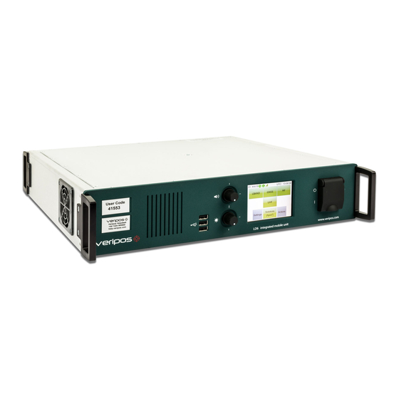
LD6 Operation 2.3 Views and controls Figure 2 LD6 Figure 3 LD6 Front Panel Controls NOTE Audio is not implemented on the LD6. Figure 4 LD6 Rear Panel Connectors LD6 (Version 8 & Version 50) Operations Manual 14(85) - Page 16 Previously, a GA-530 GNSS antenna may have been supplied if Glonass was not required. The V460 is the standard antenna currently supplied for GNSS signals on an LD6 regardless of whether Glonass is required or not. The Video out connection is only used with Verify-QC and Orion software If using a combined L-Band / GNSS antenna (e.g.
-
Page 17: Ld6 Start Up
Wait a few minutes while a self-test is performed. Following successful test you will see the main or home screen. The LD6 is disabled when first started. Before a beam is selected and the unit is enabled the L-Band icon will be red. - Page 18 NMEA output selection Settings –Set up of position output ports, reference stations and network configuration Figure 6 shows an enabled LD6 touch screen. Four of the six rear bays are equipped with receiver cards. Two bays are for future use.
-
Page 19: L-Band Receiver Configuration
Antenna power must be toggled on (Home/ LBand/ Antenna is off) when the L-Band card is directly connected to an L-Band antenna. The Antenna power should be toggled off where the LD6 is connected to a powered signal splitter or other external equipment. 2.5.2... - Page 20 LD6 Operation After turning on the LD6, touch the LBAND button. The L-Band screen is displayed: To select a Beam to receive VERIPOS Corrections – Refer to the L-band Coverage Map and select the correct satellite beam for your area.
- Page 21 The ‘S’ (Sync) icon will turn from red to green when a usable beam is correctly selected and signals are received. To view overall L-Band signal status and confirm a beam is being received - select Home/ LBAND/ Status. LD6 (Version 8 & Version 50) Operations Manual 20(85)
-
Page 22: Custom Entry Of User Beam Frequency
User Beams should only be selected under direction from VERIPOS. User Beams are not used during normal LD6 operation. Custom entry of a user Beam is provided to allow the user to manually configure a Beam frequency and bit rate for reception of Veripos L-Band corrections. -
Page 23: View And Edit Reference Stations
The LD6 L-Band card outputs two data streams of RTCM corrections:- RTCMa and RTCMb. These may be configured independently and both may be selected for output on the LD6 COM or LAN ports RTCMa is additionally used internally, providing correction information to the LD6 internal position computation. - Page 24 LD6 Operation Recommendation On the RTCMa data stream all reference stations should be set to enabled. The LD6 internal calculations will determine automatically the best stations for use. Use RTCMb to provide output of corrections to third party equipment. Depending on the application it may be desirable for the user to select the appropriate stations for this equipment.
-
Page 25: View L-Band Station Status
Reference stations on RTCMa are used internally and are also available for output to other devices. Veripos recommend in most cases that all stations are enabled. The LD6 will use up to a maximum of eight reference stations for VERIPOS Standard solutions, depending on user’s location and LD6 variant. -
Page 26: Gnss Receiver Config And Status
Antenna power must be toggled On (Home/ GNSS/ Antenna is off) when the GNSS card is directly connected to a GNSS antenna. The Antenna power should be toggled off where the LD6 is connected to a powered signal splitter or other external equipment. LD6 (Version 8 & Version 50) Operations Manual... -
Page 27: Gnss Status
2.6.2.1 GLONASS Constellation Where the screen entry “GLO SV’s tracked” shows 0 (zero), VERIPOS services using GLONASS will not be available. The GNSS receiver can, (as an option), be provided with the capability to receive position information from the GLONASS satellite constellation. When GLONASS SV’s are being tracked by the Septentrio AsteRx card, the number of SV’s tracked... -
Page 28: Gnss Config
Menus for PPS polarity profile settings and information on Event Markers. 2.6.3.1 NMEA Config NOTE If using Veripos Services, the output message settings for Veripos Solutions are set in Solutions/ Config/ NMEA. The GNSS/ Config/ NMEA Config page within is used when: •... - Page 29 Touch Close when finished. 2.6.3.2 PPS Settings Use the Edit button, arrow keys and Enter button to amend settings of pulse polarity characteristics between Low-to-High and High-to-Low. Touch Close when finished. LD6 (Version 8 & Version 50) Operations Manual 28(85)
-
Page 30: Module Reboot
The event marker function is not implemented on the LD6. 2.6.4 Module Reboot This will perform a reboot on the GNSS module without rebooting other modules and the full LD6 system. If using this function it will then lead to all position calculations being reset. 2.6.5 Factory Reset Use only under instruction from a VERIPOS engineer. -
Page 31: Mf Receiver Sbx-4
LD6 Operation 2.7 MF Receiver SBX-4 The MF SBX-4 card (where fitted) allows for reception of non-VERIPOS MF Marine Beacon and IALA differential corrections Access from Home/ MF to configure for use. When required, toggle the Antenna power button to Antenna is on (default is off). -
Page 32: Status
Frequency of the received station Rate: Data baud rate of the received transmission The signal strength received in dB µV/m SNR: The current signal to noise ratio in dB/Hz WER: The word error rate LD6 (Version 8 & Version 50) Operations Manual 31(85) -
Page 33: Mf Config
AUTOMATIC Searches for strongest signal AUTODISTANCE Configures for closest MF reference station Selects only from stations in the LD6 database NOTE: not available when in QC Mode. MANUAL User entered frequency and bit rate To change operating mode, touch the Edit button to amend the card channel setting. - Page 34 Next use the Manual Tuning arrow on the right to Edit the Frequency and then the Bitrate for the channel required. When the Bitrate is entered press Update button then touch Close. LD6 (Version 8 & Version 50) Operations Manual 33(85)
-
Page 35: Uhf Receiver
Channels 10 to 12 are available for user configuration. Touch the onscreen UHF button to display Status and Config options. The Module Reboot will perform a reboot to the module and save a full LD6 reboot. The Factory Reset button should only be used under direction from VERIPOS. - Page 36 Signal Strength SNR = Signal to Noise Ratio 2.8.1.2 Tuning Summary UHF/ Status/ then use arrow keys Displays the Channel number used, Frequency entered, baud rate, protocol, Modulation, FEC and Sensitivity. LD6 (Version 8 & Version 50) Operations Manual 35(85)
-
Page 37: Configuration
Where the UHF RTCM signal is lost the time will increment up to 300 seconds then show >300 s. 2.8.2 Configuration Configuration is accessed from Home/UHF/Config. NOTE When amending the UHF receiver card configuration the output of UHF RTCM data is interrupted. LD6 (Version 8 & Version 50) Operations Manual 36(85) - Page 38 Manual Frequency entry To manually enter details for a UHF frequency: Home/ UHF/ Config/ Yes/ Tune/ Edit Select using the Arrows to show the required Channel number then press the Edit button. LD6 (Version 8 & Version 50) Operations Manual 37(85)
- Page 39 Forward Error Correction on or off • Switch Sensitivity between Low, Medium and High. When finished entering information return to the Status section (Home/ UHF/ Status) to review the RTCM data delay and channel settings applied. LD6 (Version 8 & Version 50) Operations Manual 38(85)
- Page 40 Only use when the UHF module is not operating correctly. UHF – Factory Reset 2.8.2.4 This function should only be used under direction of a VERIPOS representative. All user configurations are deleted. LD6 (Version 8 & Version 50) Operations Manual...
-
Page 41: Ld6 Solutions
LD6 Operation 2.9 LD6 Solutions Depending on the services enabled by the VERIPOS service code (Access code), the LD6 processor and software will simultaneously compute up to three different position solutions. Only ONE of these may be a PPP solution. -
Page 42: Solutions
• NMEA – these message streams can be selected as part of the output from the LD6 to ships system and allows the setup of up to three message streams (Out 1, 2 and 3) using the following message types: GGA, GGX, VTG, GLL, GSA, GRS, GSV, GST, RMC, ZDA Up to three message streams can be classified as ‘Best’, ‘Std²’... -
Page 43: Config
You can edit the elevation mask of all DGNSS services such as Standard and Standard². For PPP services such as Ultra or Apex – the Elevation mask cannot be configured (default 7°). LD6 (Version 8 & Version 50) Operations Manual 42(85) - Page 44 Touch the Enter button when finished. Solutions / Config/ Correction Input/ Edit This menu option is used in LD6 units when fitted with MF and/or UHF receivers. Use this menu to Enable or Disable the Receiver card(s). LD6 (Version 8 & Version 50) Operations Manual...
- Page 45 This section allows users to switch between High accuracy PPP services. NOTE The LD6 will only compute and output ONE PPP solution. Users can switch between High Accuracy PPP solutions but must allow for service convergence time before high accuracy position output.
-
Page 46: Nmea
When all messages required for that solution are selected, touch the Finish arrow. The LD6 will confirm that you wish to reset the output port. NOTE During change there may be no output of position data. -
Page 47: Actions
2.10.3 Shutdown To shut down the LD6 go to Actions/ Shutdown/ Yes. 2.10.4 Factory Reset Touch to perform a Factory Reset of the LD6. Use under guidance from a Veripos Technician. LD6 (Version 8 & Version 50) Operations Manual 46(85) -
Page 48: Display Config
2.10.5.1 Display Select The Display Select menu is only relevant when a touch-screen enabled external monitor is connected to the LD6. This setting allows the correct drivers to be installed. The supported touch-screen monitors are Hatteland and Norco. Contact VERIPOS for further advice for use of other external touch-screen monitors. - Page 49 Icon is greyed out if already in use or another application is launched. Exit the application that is being used to make the launch button available. For details in the use of this software refer to the Verify QC for LD6 manual. LD6 (Version 8 & Version 50) Operations Manual...
-
Page 50: Calibrate Screens 1/2
A mouse can be used to control both screen 1 and screen 2. To move the mouse from the LD6 screen on to the external monitor, drag the mouse to the right. To mouse the mouse from the external monitor to the LD6 screen, drag the mouse to the top left of the monitor. -
Page 51: Settings
2.11.1 Day/Night Mode Day / Night display (toggle) Day/night toggle setting of the LD6 screen, press the yellow “dot” button to switch screen display between night and day setting. When in night mode the yellow “dot” appears further away (smaller) and a darker shade. -
Page 52: Status
LD6 Operation 2.11.2 Status This provides access to overall system status for the LD6; use the right hand side arrow keys to review: • Application system version • Fan speeds • Temperature sensor readings • System resource 2.11.3 I/O - Input/output COM port setup... - Page 53 The same RTCM data is supplied to the LD6 internal calculations Veripos recommend that all reference stations are enabled on RTCMa. All Veripos algorithms are designed to automatically select the optimum stations for use in the calculation. COM2 – NMEA Solution 1 Position Output Solution 1 is the primary NMEA position output and is used to provide position data to the users’...
- Page 54 The corrections may be output to be used by Verify QC or third party equipment. (This option is designed to support the Petrobras UHF chain in Brazil. Users considering other applications should consult the VERIPOS Helpdesk for advice.) Further details for all ports are given in Section 4.
- Page 55 NMEA position data output 2 Solutions 3 NMEA NMEA position data output 3 Gyro heading input, for use with Orion. Gyro Input Head Must be in NMEA HDT or THS format. LD6 (Version 8 & Version 50) Operations Manual 54(85)
- Page 56 2.11.3.4 Multiple Data Stream Outputs Users can output the identical messages to different ports. First select an unassigned LD6 COM port e.g. COM14. Settings/ I/O and the use the Arrows to highlight the port: LD6 (Version 8 & Version 50) Operations Manual...
- Page 57 Press Next and use the Arrows to select the data streams to output to this port. Where multiple LD6 outputs of the same device/data stream are required, it is only necessary to assign the same data stream to ports. Each port may use a different protocol.
- Page 58 • 1 start bit • 8 data bits • No parity • 1 stop bit This information may be required when interfacing to ships systems using RS-232/422 standards. The LD6 is the transmitting device. LD6 (Version 8 & Version 50) Operations Manual 57(85)
-
Page 59: Network
There are two RJ45 LAN ports mounted under the power connector on the extreme left of the rear panel labelled “Ethernet”. The upper port is LAN1, the lower port is LAN2. To view the LAN Port status: LD6 (Version 8 & Version 50) Operations Manual 58(85) - Page 60 The static IP is displayed followed by “(fallback)” [this is usually an indication of a fault] Mode: Shows the mode selected in Config (either Static or DHCP) 2.11.4.3 Network / Config From the LAN menu touch the Config button to open the configuration page: LD6 (Version 8 & Version 50) Operations Manual 59(85)
- Page 61 The factory LAN DEFAULT SETTINGS are as follows: Mode: STATIC Static IP (LAN1): 192.168.002.002 Static IP (LAN2): 192.168.003.003 Subnet Mask: 255.255.255.000 Gateway Address (LAN1): 192.168.002.001 Gateway Address (LAN2) 192.168.003.001 LD6 (Version 8 & Version 50) Operations Manual 60(85)
-
Page 62: Ip Ports
[e.g. for GNSS Raw]. All I/O signals which are available on the COM ports can also be interfaced via the LAN. 2.11.5 IP Ports The LD6 IP port assignments are listed below. Data Stream IP Socket LBAND: LBR1 –... -
Page 63: Archiving Data
GNSS and RTCM data in a VERIPOS proprietary format. These files can then be sent to VERIPOS for analysis in order to determine the cause of any issues. To archive LD6 data, insert a USB memory stick into an available LD6 USB socket. The screen below will appear: Select Archive Log Files to commence archiving the raw logged data to the USB memory stick. -
Page 64: Ld6 Configuration Backup
2.13 LD6 Configuration Backup The LD6 configuration settings can be backed up onto an external USB drive if required. This allows for configurations to be saved and restored after a factory reset. This also allows for the transfer of configuration settings from one LD6 to another. -
Page 65: Use Of External Touchscreen Monitors
LD6 Operation For information relating to restoring LD6 configuration files on to an LD6, please contact the VERIPOS Helpdesk. Configuration backups can only be restored on an LD6 running on the same software version as that which the backup configuration was created from. -
Page 66: Veripos Software Compatibility
2.0.2.74 & above Verify QC (On-Board LD6) 1.12A Verify QC (on PC) 1.20 LD6 IMU’s running software version 50.2.0.2 and below are NOT compatible with the following VERIPOS software: • Quantum LD6 (Version 8 & Version 50) Operations Manual 65(85) -
Page 67: Troubleshooting
4 Troubleshooting 4.1 Overview of troubleshooting The LD6 uses a touch screen to access an embedded Windows XP operating system. The system contains no user-serviceable parts. The cover should not be removed except under the guidance of a VERIPOS engineer, first ensuring that the unit is isolated from all AC and DC power supplies. -
Page 68: Enable/Disable Faults
This can occur when the vessel is in port and/or alongside a large structure. Blockage can also be caused by the vessel’s own superstructure. This may be eliminated by changing the heading. LD6 (Version 8 & Version 50) Operations Manual 67(85) - Page 69 For Verify QC, consult the Verify QC Operations Manual for guidance on its’ use where provided in conjunction with the LD6. For problems relating to antennas or cables, see the LD6 Installation manual (AB-V- MA-00520) and the Antennas & Coaxial Cable Installation guide (GD-GL-VER- EQP- 001) before installing replacement equipment and for a general guide to equipment installation.
-
Page 70: Veripos Helpdesk
VERIPOS Online support system, VOSS at: https://help.veripos.com The VERIPOS Helpdesk is the first point of contact for technical enquiries and fault reports. It is manned 24 hours per day, 365 days per year. Helpdesk contact details are in the Contact information chapter. -
Page 71: Reference Information
(SAL). This takes the form of a contract which is agreed between the user's company and the VERIPOS Operations department. The equipment cannot be used until an enable code is obtained from the VERIPOS Helpdesk. The Helpdesk is not authorised to issue a code unless an active SAL exists, and its number can be determined. -
Page 72: L-Band Coverage Map
Reference information 5.2 L-band Coverage Map An up-to-date VERIPOS L-band Coverage Map can be found on the VERIPOS Online support system at https://help.veripos.com. -
Page 73: Ld6 Menu Structure
Reference information 5.3 LD6 Menu structure Overall Menu Structure of the LD6 L-Band Menu Structure of the LD6 LD6 (Version 8 & Version 50) Operations Manual 72(85) - Page 74 Reference information GNSS Menu Structure of the LD6 MF Menu Structure of the LD6 LD6 (Version 8 & Version 50) Operations Manual 73(85)
- Page 75 Reference information UHF Menu Structure of the LD6 Solutions Menu Structure of the LD6 LD6 (Version 8 & Version 50) Operations Manual 74(85)
- Page 76 Reference information Actions Menu Structure of the LD6 (Software version 8.2.0.3) Actions Menu Structure of the LD6 (Software version 50.2.0.2) LD6 (Version 8 & Version 50) Operations Manual 75(85)
- Page 77 Reference information Settings Menu Structure of the LD6 LD6 (Version 8 & Version 50) Operations Manual 76(85)
-
Page 78: Add User Beam
The ‘User Beam’ facility is provided for the manual entry of new satellite beams to receive VERIPOS corrections. Use this channel for your work region ONLY when advised by VERIPOS. Go to LBand/Config/Beams User Beams/Edit Use the Arrow buttons to Select from preset names, ‘User 1-3’. - Page 79 Reference information LD6 (Version 8 & Version 50) Operations Manual 78(85)
-
Page 80: Nmea Sentences
GGX is similar to GGA but the latitude and longitude are specified with increased accuracy (7 decimal places instead of 5). Because of the increased message length, some systems may not be able to decode it. LD6 (Version 8 & Version 50) Operations Manual 79(85) - Page 81 (A = data valid ; V = data not valid) mode indicator (A = Autonomous, D = Differential, E = Estimated, M = Manual, S = Simulator, N = data Not valid) *cc<CR><LF> checksum, carriage return and line feed LD6 (Version 8 & Version 50) Operations Manual 80(85)
- Page 82 64+satellite slot number. The slot numbers are 1 through 24 for the full GLONASS constellation of 24 satellites, this gives a range of 65 through 88. The numbers 89 through 96 are available if slot numbers above 24 are allocated to on-orbit spares. LD6 (Version 8 & Version 50) Operations Manual 81(85)
- Page 83 3) When multiple GRS sentences are being sent then their order of transmission must match the order of corresponding GSA sentences. Listeners shall keep track of pairs of GSA and GRS sentences and discard data if pairs are incomplete. LD6 (Version 8 & Version 50) Operations Manual 82(85)
- Page 84 64+satellite slot number. The slot numbers are 1 through 24 for the full GLONASS constellation of 24 satellites, this gives a range of 65 through 88. The numbers 89 through 96 are available if slot numbers above 24 are allocated to on-orbit spares. LD6 (Version 8 & Version 50) Operations Manual 83(85)
- Page 85 Note that, as of the 2.3 release of NMEA, there is a new field in the RMC sentence at the end just prior to the checksum. For more information on this field. LD6 (Version 8 & Version 50) Operations Manual 84(85)
- Page 86 UTC time in hours, minutes, seconds of the GPS position dd,mm,yyy Day,Month,Year (UTC) local zone hours (00 to +/-13 hrs) local zone minutes (00 to 59) *hh<CR><LF> checksum, carriage return and line feed LD6 (Version 8 & Version 50) Operations Manual 85(85)
-
Page 87: Contact Information
Contact information Contact information All initial contacts regarding technical or support issues should be initially addressed to the VERIPOS Helpdesk. Where appropriate, the Helpdesk will refer issues to the regional operations and engineering teams. 6.1 VERIPOS Helpdesk Helpdesk telephone +44 (0)1224 965900 Helpdesk e-mail helpdesk@veripos.com...