Veripos LD6 Installation Manual
Integrated mobile unit
Hide thumbs
Also See for LD6:
- Operation manual (88 pages) ,
- Quick manual (2 pages) ,
- Operation manual (87 pages)
Table of Contents
Advertisement
Quick Links
Download this manual
See also:
Operating Manual
Advertisement
Table of Contents

Subscribe to Our Youtube Channel
Related Manuals for Veripos LD6


Summary of Contents for Veripos LD6
- Page 1 Installation Manual VERIPOS...
-
Page 2: Document No. Ab-V-Ma
Document title: LD6 Installation Manual Document No. AB-V-MA-00520 Variant table updated. 03/04/17 Changes to cable termination section Info relating to new LD6 06/01/17 variants added GNSS Module tracking 20/04/16 specification updated Safety warning info 21/12/15 updated V460 antenna phase 19/08/15... -
Page 3: Table Of Contents
Front Panel ............................17 2.3.2 Rear Panel ............................17 INSTALLATION ................................. 18 INSTALLATION ............................... 18 LD6 Installation – Schematic Example 1 ................... 18 3.1.1 LD6 Installation – Schematic Example 2 ................... 19 3.1.2 SITING THE LD6 RECEIVER ..........................20 3.2.1 Ventilation Requirements ........................ - Page 4 Document title: LD6 Installation Manual Document No. AB-V-MA-00520 EQUIPMENT RACK ..............................36 Rack Installed LD6 Variant – Guidance on Installation ..............36 3.7.1 POWER AND CABLING ............................37 REFERENCE INFORMATION ............................38 TECHNICAL SPECIFICATIONS ..........................38 4.1.1 Mechanical ............................38 4.1.2...
-
Page 5: Introduction
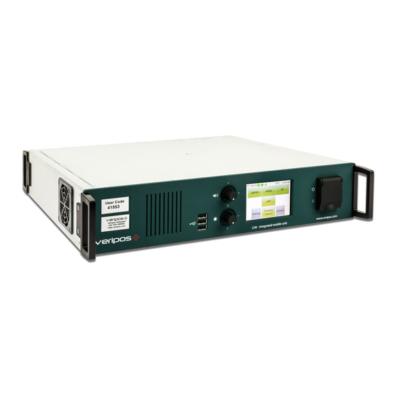
LD6 INTEGRATED MOBILE UNIT Figure 1. The VERIPOS LD6 Receiver The VERIPOS LD6 is easy to install and operate. It is an effective, flexible unit that ensures reliable reception of VERIPOS services with superior positioning from metre to decimetre level accuracy. -
Page 6: Scope
LD6 Installation Manual Document No. AB-V-MA-00520 The LD6 has a 3.5” (9 cm) colour VGA touchscreen that allows quick and easy user setup. In addition to calculating position, the LD6 can output all received data in standard formats such as RTCM and NMEA. -
Page 7: Terms And Abbreviations
Document title: LD6 Installation Manual Document No. AB-V-MA-00520 TERMS AND ABBREVIATIONS Ampere Alternating Current Apex Veripos PPP DGNSS service Antenna Reference Point American Wire Gauge Below Deck Equipment BeiDou Chinese GNSS constellation Bit Error Rate Bits Per Second Course Over Ground... - Page 8 Standard Deviation Signal to Noise Ratio Spotbeam High Power L-Band Signal Space Vehicle Ultra High Frequency Ultra Veripos High Accuracy Positioning Systems Universal Serial Bus Coordinated Universal Time Volt VDOP Vertical Dilution of Precision VERIPOS Precise navigation and positioning solutions service provider...
-
Page 9: Ld6 Safety Summary
Ensure adequate air circulation to ventilate the unit especially to the sides to avoid heat build-up. Only connect to an earthed power supply. The LD6 unit is class 1 construction and must be earthed. Connect only to a power supply with a voltage corresponding to that marked on the unit. -
Page 10: Installation
1.5.7 Fault diagnosis Follow the guidance in this document to correctly install the LD6. Where the LD6 does not perform as indicated please first check all connections before contacting your supplier or VERIPOS for assistance (contact details in the Reference information chapter). -
Page 11: Document Conventions
Please read this manual and refer to the following information where required: Antenna & Coaxial Cable Installation manual. LD6 Operations manual. Ensure manual is valid for LD6 variant in-use! LD6 Quick Guide. Information is available at VERIPOS Online Support System (VOSS): http://help.veripos.com... -
Page 12: Waste Electrical And Electronic Equipment
Replacement of Battery Risk of explosion if battery is replaced by an incorrect type. Where replacement of the battery unit in the LD6 is required, please carefully dispose of the LD6 battery as hazardous waste in line with local regulations that apply. -
Page 13: Disclaimer
Where Veripos’ intellectual property rights are alleged to be infringed by the end user, Veripos will seek to enforce its intellectual property rights in the civil courts to the fullest extent possible. Where reproduction, copying, re-engineering, adaption,... - Page 14 Document title: LD6 Installation Manual Document No. AB-V-MA-00520 This page is intentionally left blank. Rev No: Page 14 Date: 03.04.2017 LD6 Installation Manual...
-
Page 15: System Description
Controls, Connectors and I/O Ports LD6 RECEIVER OVERVIEW The VERIPOS LD6 receiver is a multi-purpose unit built on a modular design. A touchscreen colour control panel is used to set up the unit and display information. Various combinations of modules can be installed. Contact VERIPOS for further information. -
Page 16: Examples Of Ld6 Variants
OEM617D cards, which are capable of tracking up to 5 GNSS constellations. The menu structure and general operation may vary depending on the LD6 software version. Refer to the relevant LD6 Operations Manual for the software version running on your LD6. Rev No:... -
Page 17: Controls, Connectors And I/O Ports
CONTROLS, CONNECTORS AND I/O PORTS The controls etc. are detailed in this chapter. 2.3.1 Front Panel Figure 3. LD6 Front Panel 1. Labels with Unit ID (above) and phone number to Helpdesk (below) 2. Front panel speaker 3. 3 x USB 2.0 sockets 4. -
Page 18: Installation
LD6 Installation Manual Document No. AB-V-MA-00520 INSTALLATION This section provides guidance on the installation of the LD6 receiver variants. Contact your supplier or VERIPOS with questions or for advice when installing this equipment. INSTALLATION Installation work for the LD6 varies for: ... -
Page 19: Ld6 Installation - Schematic Example 2
LD6 Installation – Schematic Example 2 3.1.2 Figure 6. Example of an Installation Drawing for an LD6 – Shared L-Band & MF antenna The splitter used in the Figure 6 configuration will be supplied by VERIPOS. Normal GNSS splitters will not allow MF signals to pass through. -
Page 20: Siting The Ld6 Receiver
Document No. AB-V-MA-00520 SITING THE LD6 RECEIVER The LD6 (2U) unit is recommended to be housed in a 19" rack with suitable ventilation. 3.2.1 Ventilation Requirements The unit is designed to be ventilated at the sides. Each side of the unit should have > 55 mm clearance. - Page 21 AB-V-MA-00520 3.2.2.1 General Guidance on Rack Cable Installation Run power cabling to the LD6 up the opposite side of the rack from that used for coaxial cables. Data cables should not be run next to the power cable.
-
Page 22: Antenna Installation
Receives non-VERIPOS corrections from local UHF radio transmitters * The V460 and V86 (and optionally FUC/6) antennas are the models currently supplied by VERIPOS. The other antenna models shown are some of those which may have previously been supplied with the LD6. V460*... -
Page 23: Gnss Antenna
3.3.2 GNSS antenna The GNSS antenna receives transmissions from multiple GNSS satellites. This section describes best practice when positioning and installing your GNSS antenna. For more details please refer to VERIPOS “Antenna & Coaxial Cable Installation Manual”. 3.3.2.1 General The GNSS antenna is used for vessel positioning and therefore its mounting location is of high importance to the system. - Page 24 Document title: LD6 Installation Manual Document No. AB-V-MA-00520 Figure 11. Good installation – GNSS antennas installed on top of the mast, minor signal masking from mast light at low elevations If antennas cannot be installed directly at the top of the mast/ships structure, it is essential that the mounting point is sufficiently strong for this purpose.
-
Page 25: L-Band Antenna
Form cable below the antenna into a small loop, approximately150–220 mm (6 to 8in) in diameter. Attach the loop to the mounting pole under the antenna to provide strain relief from the cable. For more detailed guidance please refer to the VERIPOS document “Antenna and Coaxial Cable Installation Guide” (GD-GL-VER-EQP-801). 3.3.3 L-Band Antenna Figure 14. - Page 26 Refer to the ‘Scope of Supply’ and ‘Equipment Packing List’ documentation for details where variants make use of this way of delivering L-band correction signals to the LD6. Where a vessel is fitted with an Inmarsat Communications system, this may be used to receive the VERIPOS L-band correction signals in place of an Omni-directional (SPOT) antenna.
-
Page 27: Mf Beacon Antenna
Damage may occur if the L-Band antenna voltage is set to “ON” in the MMI when connected to an Inmarsat Communications system. The voltage on the L-Band connection can be turned off using the LD6 MMI. Follow instructions in the LD6 Operations manual (AB-V-MA-00521) to disable voltage output in software. -
Page 28: Coaxial Cable Installation
LDF4-50 130m / 425 ft 110m / 360 ft 210m / 700 ft 350m / 1148 ft Longer cable runs may be achievable with the use of in-line amplifiers. Contact VERIPOS for guidance. 3.4.4 General • VERIPOS recommended cable for the antenna runs is LMR 400. - Page 29 1. The total length of the cable run does not exceed the supplied cable length for this installation. Contact your supplier or VERIPOS if this is the case. 2. The cable does not cross or run parallel with any single phase or three phase mains cable (110 VAC, 220 VAC or 440 VAC) or any high power RF cables leading to transmitting devices such as Inmarsat B and VSAT domes.
-
Page 30: Coaxial Connections To Ld6 Modules
*) Other antenna types are available. The antenna types listed are those currently supplied with the LD6 as standard. The LD6 will not function correctly if the antenna connections for GNSS and L-Band are reversed. Confirm the GNSS antenna is connected to the GNSS port and the Spotbeam/Inmarsat Interface is connected to the L-Band port. -
Page 31: Combined L-Band/ Gnss Antenna Variant
3.5.2 Combined L-Band/ GNSS Antenna Variant There is an option to use a combined GNSS and L-band antenna with the LD6 unit. To utilise this option the combined GNSS/ L-Band antenna is connected to the L-Band Input. A short coaxial cable terminated with TNC Plugs is then connected between the L- Band module RF Output and the GNSS module RF Input (as shown below). -
Page 32: Interface
The LD6 has 14 serial Com ports (RJ45 female connectors RS-232/422 protocol) on rear panel, COM 1 to COM 14. Pin-outs are detailed in the Reference information chapter. The LD6 ports may be configured in software to perform various functions. Use of ports and external equipment interfaced is specific to each installation. -
Page 33: 1Pps Output Option
See the Reference information chapter for pin-out details and contact VERIPOS for advice where required. 3.6.3 1PPS Output Option Some LD6 variants provide a facility for output of a 1PPS (one pulse per second) signal, used by external equipment for accurate time synchronisation to navigation systems or multi-beam sonar. 3.6.4 Ethernet Interface Two Ethernet RJ45 connectors are fitted on the LD6 rear panel. - Page 34 LD6 Internal solution. NMEAa 19017 GNSS NMEAb LD6 Internal solution. NMEAb 19018 GNSS NMEAc LD6 Internal solution. NMEAc *LD6’s on software version 103.0.0.8 and above are not compatible with Verify QC. Rev No: Page 34 Date: 03.04.2017 LD6 Installation Manual...
- Page 35 This section details the types of data cables connected to systems and used by systems on the vessel. Data interface cables from the LD6 will use RJ45 connectors. The data interface cabling attaches to the LD6 ports for input and output of data. Cables and adapters supplied: RJ45 –DB9 female serial converters (Qty. supplied...
-
Page 36: Equipment Rack
Ventilation slots and apertures must not be obscured. Earth connection on the rear of the LD6 must be connected to ship’s ground. The rack frame and base plate should be individually grounded. Power supply for the units should be taken from a clean-power source as detailed in the ‘Scope of Supply’... -
Page 37: Power And Cabling
Units are supplied as standard with an IEC C13 rewireable AC power cable. See the Reference information chapter for details. Where a DC power supply is to be used on LD6 units running software version 50.0.0.2 or above, an external DC filter unit should be used. Contact VERIPOS if a DC filter unit is required. -
Page 38: Reference Information
4.1.2.1 Safety Considerations Although the test conditions for the LD6 units provide for a maximum operating temperature of 55 °C, continuous operation of all electronic components should if possible take place at ambient temperatures of only 25 °C. This is a prerequisite for long life and low service costs. -
Page 39: Electrical
Document title: LD6 Installation Manual Document No. AB-V-MA-00520 4.1.3 Electrical AC power input 100–240 VAC DC power input 12–24 VDC Power consumption 100 W max. AC power connector IEC Connector C13, rewireable, straight (see the Reference information chapter for details) -
Page 40: Antennas
One external rear-mounted VGA/SVGA/XVGA/SXVGA video port. 4.1.4.5 Power Supplies LD6 can operate from 110/240 VAC and / or 12/24 VDC supply. The LD6 can run on an AC or DC supply or both. If both are used this provides redundancy in case one supply fails. -
Page 41: Summary Specification Of Antennas
Document title: LD6 Installation Manual Document No. AB-V-MA-00520 4.1.6 Summary Specification of Antennas 4.1.6.1 V460 L-Band GPS L1 / L2 / L5 GLONASS L1 / L2 Galileo E1 / E5 BeiDou B1 / B2 QZSS L1C / L2L Fitted with a narrow band filter for interference rejection... - Page 42 Document title: LD6 Installation Manual Document No. AB-V-MA-00520 4.1.6.2 V460 Phase Centre Details The diagram below shows the antenna reference point (ARP) from which the phase centre values are measured. It also shows the V460 vertical (Up) phase centre values...
- Page 43 Document title: LD6 Installation Manual Document No. AB-V-MA-00520 4.1.6.3 A gain 36dB DC Voltage input 5.0 to 15.0V Fitted with a narrow band filter for interference rejection RF input connector N-type female Material Weather proof polymer plastic Standard land survey 5/8” tripod thread connector...
-
Page 44: Legacy Antennas
Document title: LD6 Installation Manual Document No. AB-V-MA-00520 4.1.7 Legacy Antennas 4.1.7.1 AD491 Features Combined L1/L2 GNSS and DGPS antenna with interdigital filters Ruggedized marine antenna Omni-directional Patch antenna Integrated cavity filter for interference rejection Technical specifications Antenna radiation pattern... - Page 45 Document title: LD6 Installation Manual Document No. AB-V-MA-00520 4.1.7.2 Main 283.5 – 325 kHz MF Beacon frequency range Beacon LNA gain 30 dB Options 1.555 – 1.585 GHz (L1) L-Band frequency range L-Band LNA gain 30 dB GNSS reception GPS, GNSS frequency 1.575 GHz (L1)
- Page 46 Document No. AB-V-MA-00520 4.1.7.3 90984 Features Ruggedized marine antenna Omni-directional helical antenna gives good performance in Veripos spot beam coverage Integrated cavity filter for interference rejection - Output at L-band (no downconverter) Technical specifications Antenna radiation pattern Omni-directional Antenna polarisation Antenna frequency 1525–1559 MHz...
-
Page 47: Antenna Cables - Specifications
Antenna Cables – Specifications 4.1.8 Typically VERIPOS provide with the system pre-terminated cables and tails for use with both L-band and GNSS/GPS antennas (see the ‘Equipment Packing List’). VERIPOS recommend use of Times Microwave coaxial LMR cable for installation of all antennas. - Page 48 Document title: LD6 Installation Manual Document No. AB-V-MA-00520 4.1.9.2 GNSS Module (AsteRx2) Product Features: Dual-frequency L1/L2 code/carrier tracking of GPS and GLONASS signals 48 hardware channels for simultaneous tracking of all visible satellites in GPS and GLONASS constellations A ‘Posteriori Multipath Estimator’ technique (APME)
- Page 49 Document title: LD6 Installation Manual Document No. AB-V-MA-00520 4.1.9.3 GNSS Module AsteRx2e Product features: Dual-frequency L1/L2 code/carrier tracking of GPS and GLONASS signals 136 hardware channels for simultaneous tracking of all visible satellites in GPS and GLONASS constellations ...
- Page 50 Document title: LD6 Installation Manual Document No. AB-V-MA-00520 4.1.9.4 GNSS Module (Novatel OEM615) Product features: Dual frequency L1/L2 tracking of GPS & GLONASS signals Multipath mitigating technology 120 channels SBAS Tracking Novatel ASCII and binary logging Technical Specifications: Operating Temperature -40 to +85°C...
- Page 51 Hot Start <35sec Signal Reacquisition <0.5sec (Avg) <1sec (Avg) Time Accuracy 20ns RMS *Galileo tracking is not currently supported on the LD6 but will be added in a future software release. Rev No: Page 51 Date: 03.04.2017 LD6 Installation Manual...
- Page 52 LD6 Installation Manual Document No. AB-V-MA-00520 4.1.9.6 MF Module (MF Module SBX-4) The LD6 variant may optionally have this card installed. A two channel MF demodulator compatible with third party MF beacon transmissions. Operating specifications Channels 2-channel parallel tracking Frequency range 283.5 to 325.0 kHz...
- Page 53 Document title: LD6 Installation Manual Document No. AB-V-MA-00520 4.1.9.7 UHF Module ADL Foundation Optional single channel data receiver module. Operating specifications Power External 6.0–30.0 VDC ±0.50 VDC During Rx 0.6 W nominal During Tx 6 W nominal @ 1 W output...
-
Page 54: Cabling And Connectors
This section contains details on the AC and DC power connectors and the cable termination used for connection to antennas. When working with these connectors and power, please refer to section 1.5 LD6 Safety summary. VERIPOS recommend that prefabricated main cables and coaxial tails are used for connection of antenna to the VERIPOS below decks equipment. - Page 55 Document title: LD6 Installation Manual Document No. AB-V-MA-00520 Material, housing Thermoplastic, black, UL 94V-0 Power cable Conform to IEC 60950-1 *) Figure 26. AC power cable installation *) Use PVC flexible cord in accordance with IEC 60227 (H03VV-F or H03VVH2-F). The temperature rating of the cord is 60 °C or higher and core conductor area of 0.5 mm2 is required...
-
Page 56: Dc Power Connector
AB-V-MA-00520 4.2.2 DC Power Connector If using an LD6 running software version 50.0.0.2 or above, a DC filter unit must be used. Refer to section 4.2.2.1 for further information. The DC power connector is a Neutrik NL4FX. Details on this connector including its termination are below. Alternatively you may use a Switchcraft HPCC4F connector. - Page 57 DC power source. Please contact VERIPOS if a DC filter unit is required. The DC filter unit should be connected to the vessel Earth point and to the LD6 chassis, as shown in Fig. 29 (below): Figure 29. DC Filter Unit...
-
Page 58: Times Lmr 400 Coaxial Cable
Document title: LD6 Installation Manual Document No. AB-V-MA-00520 4.2.3 Times LMR 400 Coaxial Cable 4.2.3.1 Electrical Specifications Performance Units (Metric) Property Velocity of propagation Dielectric constant 1.38 Time delay nS/ft (nS/m) 1.20 (3.92) Impedance ohms Capacitance pF/ft (pF/m) 23.9 (78.4) -
Page 59: Times Lmr 240 Coaxial Cable
Document title: LD6 Installation Manual Document No. AB-V-MA-00520 4.2.4 Times LMR 240 Coaxial Cable 4.2.4.1 Electrical Specifications Performance Property Units (Metric) Velocity of propagation Dielectric constant 1.42 Time delay nS/ft (nS/m) 1.21 (3.97) Impedance Ohms Capacitance pF/ft (pF/m) 24.2 (79.4) -
Page 60: Lmr 400 - Times Microwave Tc-400-Nm N-Type Male Connector
AB-V-MA-00520 LMR 400 – Times Microwave TC-400-NM N-Type Male Connector 4.2.5 The below connectors are those most commonly used by VERIPOS. For further information, such as connector termination instructions, please refer to the “Antenna and Coaxial Cable Installation Manual”. LMR400 Connectors ... -
Page 61: Interface And Serial Port Information
LD6 Installation Manual Document No. AB-V-MA-00520 INTERFACE AND SERIAL PORT INFORMATION This details the pin out details for the LD6 receiver connections. Ports COM 1 to COM 14 on the rear panel are 8 pin RJ45 female connectors. 4.3.1 LD6 COM Ports Default configuration for each COM port is: ... -
Page 62: Contact Information
Document No. AB-V-MA-00520 CONTACT INFORMATION All initial contacts regarding technical or support issues should be initially addressed to the VERIPOS Helpdesk. Where appropriate, the Helpdesk will refer issues to the regional operations and engineering teams. VERIPOS HELPDESK Helpdesk telephone +44 (0)1224 965900 Helpdesk email helpdesk@veripos.com...
Need help?
Do you have a question about the LD6 and is the answer not in the manual?
Questions and answers