Veripos LD6 Operation Manual
Hide thumbs
Also See for LD6:
- Installation manual (62 pages) ,
- Quick manual (2 pages) ,
- Operation manual (87 pages)
Table of Contents
Advertisement
Quick Links
Advertisement
Table of Contents

Related Manuals for Veripos LD6


Summary of Contents for Veripos LD6
- Page 1 LD6 Operations Manual B Variant VERIPOS Date: 21.12.2017...
- Page 2 Procedure Title: LD6 Operations Manual (B Variant) File Ref.: AB-V-MA-00589 21.12.2017 Update for new release version Variant table updated. 30.03.2017 Touchscreen section added VERIPOS Software 11.01.2017 Compatibility section added Touchscreen options added. QC 04.08.2016 Mode removed from settings 08.03.2016 Approved for release 07.01.2016...
-
Page 3: Table Of Contents
VERIPOS ONLINE SUPPORT SYSTEM (VOSS) ................9 DISCLAIMER ............................10 WASTE ELECTRICAL AND ELECTRONIC EQUIPMENT ..............11 LD6 OPERATION ............................12 VARIANTS ............................13 DO’S AND DON’TS FOR LD6 ......................14 FRONT AND REAR PANEL OVERVIEW ..................15 2.3.1 Front Panel ........................15 2.3.2 Rear Panel ........................ - Page 4 Actions .......................... 71 ADD USER BEAM ..........................72 COM AND LAN PORT INFORMATION ..................... 73 5.5.1 LD6 Serial Cable Wiring ....................73 VERIPOS REFERENCE STATIONS ....................74 QUALITY STANDARDS ........................76 NMEA SENTENCES .......................... 80 VERIPOS CONTACT INFORMATION ......................88...
-
Page 5: Introduction
Throughout this manual reference will be made to the VERIPOS Helpdesk. The Helpdesk is provided by VERIPOS and is the first point of contact for technical enquiries and assistance. It is manned 24 hours per day, 365 days per year. -
Page 6: Terms And Abbreviations
Procedure Title: LD6 Operations Manual (B Variant) File Ref.: AB-V-MA-00589 TERMS AND ABBREVIATIONS Apex VERIPOS PPP GNSS service Bit Error Rate Course over Ground Carriage Return Central Reference Point DGNSS Differential GNSS DGPS Differential GPS Dilution of Precision Dynamic Positioning... - Page 7 Procedure Title: LD6 Operations Manual (B Variant) File Ref.: AB-V-MA-00589 Coordinated Universal Time VDOP Vertical Dilution of Precision Video Graphic Array VOSS VERIPOS Online Support System WAAS Wide Area Augmentation System WEEE Waste Electrical and Electronic Equipment Word Error Rate...
-
Page 8: Document Conventions
Procedure Title: LD6 Operations Manual (B Variant) File Ref.: AB-V-MA-00589 DOCUMENT CONVENTIONS 1.4.1 Typographical Conventions Italic or bold text is used to emphasize certain parts of the information. Italic is also used in cross-reference to other parts of the document. -
Page 9: Veripos Helpdesk
VERIPOS encourage all users to promptly report problems or operating queries to the Helpdesk so that they may receive assistance. The VERIPOS Helpdesk is the first point of contact for technical enquiries and fault reports. It is manned 24 hours per day, 365 days per year. -
Page 10: Disclaimer
(including legal costs), expenses and liabilities of any kind and nature, invoked against Veripos by any third party, for or arising out of, any alleged infringement of any patent or proprietary or protected right arising out of or in... -
Page 11: Waste Electrical And Electronic Equipment
RoHS (Restriction of Hazardous Substances) complements the WEEE directive by banning the presence of specific hazardous substances in the products at the design phase. The WEEE directive covers all VERIPOS products imported into the EU as of August 13 2005. EU-based manufacturers, distributors, retailers and importers are obliged to finance the costs of recovery from municipal collection points, reuse, and recycling of specified percentages per the requirements contained in the WEEE Directive. -
Page 12: Ld6 Operation
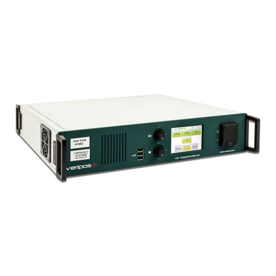
LD6 Operations Manual (B Variant) File Ref.: AB-V-MA-00589 LD6 OPERATION The controls for working with the LD6 are all available via the touch screen front panel. Use the LD6 touch screen to configure the unit. LD6 IMU Description The LD6 Integrated Mobile Unit (IMU) is used offshore on vessels to provide high precision Satellite Positioning Services from VERIPOS. -
Page 13: Variants
LD6’s will be capable of computing GPS+GLONASS solutions (provided the LD6 is enabled on an appropriate VERIPOS service). Variants with an MF module installed allow the LD6 to be capable of receiving third party corrections directly from local reference stations (where available). -
Page 14: Do's And Don'ts For Ld6
LAN port. The adapter wiring is not compatible with serial COM ports. Do connect external monitor (where required) to the rear VGA connector prior to switching on the LD6. If a monitor is connected after LD6 is switched on, it will not be detected. DON’TS ... -
Page 15: Front And Rear Panel Overview
Procedure Title: LD6 Operations Manual (B Variant) File Ref.: AB-V-MA-00589 FRONT AND REAR PANEL OVERVIEW 2.3.1 Front Panel Fig.3 LD6 IMU LD6 front panel controls There is currently no audio features enabled on the LD6. Rev No: Page 15... -
Page 16: Rear Panel
BAND receiver card. Remove the terminator from the RF out of the L-BAND card and link the GNSS card RF in to the L-BAND RF out connector, using the lead which is supplied. LD6 antenna connection using a combined GNSS & LBAND antenna Rev No:... -
Page 17: Ld6 Start-Up
Wait a few minutes while a self-test is performed. Following successful test you will see the main or home screen. The LD6 is disabled when first started. Before a beam is selected and the unit is enabled the LBAND icon will be red. - Page 18 10. Settings –Set up of position output ports, network configuration and provides general status information. The above Home Screen shows an enabled LD6 touch screen. Four of the six rear bays are equipped with receiver cards. Two bays are for future use.
-
Page 19: L-Band Receiver
Procedure Title: LD6 Operations Manual (B Variant) File Ref.: AB-V-MA-00589 L-BAND RECEIVER This section describes how to view L-Band status information and configure L-Band settings as required. 2.5.1 Status – L-Band To view L-Band status, from the Home screen, press LBAND / Status: Confirm ‘Frame Sync’, ‘Signal Lock’... -
Page 20: L-Band Configuration
2.5.1.1 Module Info – L-Band From the L-Band Status page, press Module Info: The Module Info screen shows: Slot – Indicates which LD6 module bay the L-Band card is physically installed in. Variant – Details of the L-Band card model installed. ... - Page 21 Up to date copies and service update information available on VERIPOS online support system (VOSS) at: http://help.veripos.com You need to know the VERIPOS beam(s) that cover the general area of operation for the vessel. To ensure correct beam selection when configuring the LD6 use the VeriChart program.
- Page 22 User Beams should only be selected under direction from VERIPOS. User Beams are not used during normal LD6 operation. Custom entry of a user Beam is provided to allow the user to manually configure a Beam frequency and bit rate for reception of VERIPOS L-BAND corrections.
- Page 23 The LD6 L-BAND card outputs two data streams of RTCM corrections:- RTCMa and RTCMb. These may be configured independently and both may be selected for output on the LD6 COM or LAN ports. RTCMa is additionally used internally, providing correction information to the LD6 internal position computation.
- Page 24 Reference stations on RTCMa are used internally and are also available for output to other devices. VERIPOS recommend in most cases that all stations are enabled. The LD6 will use the closest six (maximum) stations provided they are within 1500km of the users current location.
-
Page 25: Access Info - L-Band
The Access Info page shows details of the VERIPOS services which the LD6 is currently enabled for. This page is accessible from Home/ LBAND/ Access Info: If the LD6 is disabled, the Access State field will say “Disabled”. Disabled units will list the services which the LD6 was last enabled for. -
Page 26: Enable For Veripos Corrections
The Helpdesk will enable the requested services for the LD6 over the air. If after requesting the LD6 to be enabled the Access Info page still shows Disabled, confirm the LD6 still has Sync (S on the Home screen) and contact the VERIPOS Helpdesk. -
Page 27: Gnss Receiver
LD6 Operations Manual (B Variant) File Ref.: AB-V-MA-00589 GNSS RECEIVER The LD6 GNSS menu is used to check GNSS status and to configure position calculations etc. 2.6.1 GNSS Receiver Status The GNSS Status menu is accessed via Home/ GNSS/ Status. - Page 28 Example screen shows a GNSS card which has capability to receive both GPS and GLONASS satellite signals. All LD6 receivers with NovAtel GNSS cards fitted are capable of tracking both GPS and GLONASS. Touch View SV Info to view each satellite in the constellation(s) in turn.
- Page 29 The Pos Info page displays the following information regarding the solution being calculated by the LD6: Status – States the solution currently calculated by the LD6 e.g. Apex, Ultra. Latitude – In DD° MM’ SS.SSSS” format (WGS84) ...
-
Page 30: Config - Gnss
AB-V-MA-00589 2.6.1.5 Masks Displays the following LD6 elevation masks: Tracking Elevation Mask – The LD6 will track all available satellites down to this elevation. DGNSS Elevation Mask – The LD6 will only use available satellites above this elevation in any DGNSS solutions e.g. VERIPOS Standard. - Page 31 Touch Edit then use the arrow icons to select the desired PPP solution. Press Enter to confirm the selection and then Close. The LD6 will need to be enabled for the correct access code in order to be able to output the selected solution.
- Page 32 The LD6 will always output the best available position, for example, if the LD6 is configured to calculate an Apex solution and Apex fails, the output will automatically output the next best available position e.g.
- Page 33 If the PPP DQI setting is set to 5 on this page, the DQI value in the GGA output will be 2 for all Differential solutions (e.g. VERIPOS Standard, 3 Party) but will be 5 for PPP solutions.
- Page 34 Procedure Title: LD6 Operations Manual (B Variant) File Ref.: AB-V-MA-00589 Use the Up/ Down arrows to change the values and the Right arrow to change between the Precision and PPP DQI fields. Press Enter to confirm the changes then Close.
-
Page 35: Antenna Voltage - Gnss
Antenna power must be toggled On (Home/GNSS/Antenna is off) when the GNSS card is directly connected to a GNSS antenna. The Antenna power should be toggled off where the LD6 is connected to a powered signal splitter. 2.6.4 Module Reboot - GNSS The Module Reboot option with the GNSS menu will perform a reboot of the GNSS card only (not the entire LD6 receiver). -
Page 36: Mf Reciever
LD6 Operations Manual (B Variant) File Ref.: AB-V-MA-00589 MF RECIEVER The MF SBX-4 card (where fitted) allows for reception of non-VERIPOS MF Marine Beacon and IALA differential corrections. Access from Home/ MF: 2.7.1 Status - MF Touch the Status icon. This shows the device status screens for the MF card (MF-SBX4) and gives access to MF card Module info and available channels for correction data. - Page 37 Procedure Title: LD6 Operations Manual (B Variant) File Ref.: AB-V-MA-00589 The RTCM entry shows the correction age in seconds. In normal use this will correct every few seconds. If the MF RTCM signal is lost the time will increment up to 300 seconds then show >300 s.
-
Page 38: Config - Mf
File Ref.: AB-V-MA-00589 2.7.2 Config - MF Use Home/ MF/ Config to edit the operating mode of the SBX-4 card between Automatic and Manual. VERIPOS recommend the use of AUTOMATIC mode. Operating mode options: AUTOMATIC Searches for strongest signal MANUAL User entered frequency and bit rate To change operating mode, touch the Edit button to amend the card channel setting. -
Page 39: Antenna Voltage - Mf
Antenna power must be toggled On (Home/ MF/ Antenna is off) when the MF card is directly connected to an MF antenna. The Antenna power should be toggled off where the LD6 is connected to a powered signal splitter. 2.7.4 Module Reboot - MF The Module Reboot option with the MF menu will perform a reboot of the MF card only (not the entire LD6 receiver). -
Page 40: Uhf Receiver
Procedure Title: LD6 Operations Manual (B Variant) File Ref.: AB-V-MA-00589 UHF RECEIVER The UHF receiver card is an optional receiver. The card comes preconfigured for use with Petrobras systems. Channels 1 to 9 have channels as specified by Petrobras but can be reconfigured if required. - Page 41 Procedure Title: LD6 Operations Manual (B Variant) File Ref.: AB-V-MA-00589 2.8.1.3 Tuning Summary Displays the Channel number used, Frequency entered, baud rate, protocol, Modulation, FEC and Sensitivity. 2.8.1.4 Device Status Displays the time in seconds elapsed from the last RTCM string received.
-
Page 42: Configuration
Procedure Title: LD6 Operations Manual (B Variant) File Ref.: AB-V-MA-00589 2.8.2 Configuration Configuration is accessed from Home/ UHF/ Config. When amending the UHF receiver card configuration the output of UHF RTCM data is interrupted. Amend the Frequency, Channel, Forward Error Correction, Sensitivity and Link Speed using the onscreen arrows and buttons. - Page 43 Procedure Title: LD6 Operations Manual (B Variant) File Ref.: AB-V-MA-00589 2.8.2.1 Manual Frequency Entry To manually enter details for a UHF frequency: Home/ UHF/ Config/ Yes/ Tune/ Edit Select using the Arrows to show the required Channel number then press the Edit button.
-
Page 44: Module Reboot - Uhf
The module reboot will reboot the UHF module without disruption to the other receiver cards. Only use when the UHF module is not operating correctly. 2.8.4 Factory Reset - UHF This function should only be used under direction of a VERIPOS representative. 2.8.5 Hints – UHF Provides advice where available. Rev No:... -
Page 45: Settings
View and configure IP Network settings Day / Night screen toggle 2.9.1 Day / Night Mode Day/ Night toggle setting of the LD6 screen, press the yellow “dot” button to switch screen display between night and day settings. Rev No: Page 45... -
Page 46: Status
Procedure Title: LD6 Operations Manual (B Variant) File Ref.: AB-V-MA-00589 2.9.2 Status This provides access to overall system status for the LD6; use the right hand side arrow keys to review: LD6 system version Fan speeds Temperature sensor readings ... - Page 47 The choice of NMEA messages are configured using the GNSS/ Config menu. By default, the NMEA GGA message is configured. If no NMEA messages are enabled on NMEAa, the GNSS icon on the LD6 Home screen will be red. COM3 – GNSS Raw Output The GNSS Raw output is only used when connecting the LD6 to VERIPOS Verify QC software running on a separate PC.
- Page 48 All available reference stations are enabled by default however the user can enable/disable only the reference station(s) required if necessary. Unlike RTCMa, RTCMb is not used internally by the LD6 therefore disabling stations on RTCMb do not affect any NMEA position outputs from the LD6.
- Page 49 Procedure Title: LD6 Operations Manual (B Variant) File Ref.: AB-V-MA-00589 2.9.3.3 NMEA Position Output – Via COM Before configuring any output of an NMEA position, you must have first selected which NMEA message types are required by the receiving system.
- Page 50 Touch Next then select the required baud rate, data bit, stop bit and parity settings using the arrow icons. Finally, touch Finish. A summary of the I/O port settings will be displayed. Touch Yes to apply settings. For details of LD6 COM pin-outs, refer to Section 4. Rev No: Page 50...
-
Page 51: Network
AB-V-MA-00589 2.9.3.4 External RTCM Inputs As detailed in Section 2.9.3.2, it is possible to input RTCM correction data to the LD6 from external sources. It is possible to configure up to two Ext RTCM inputs. Only one RTCM data source will be used at any one time. - Page 52 Procedure Title: LD6 Operations Manual (B Variant) File Ref.: AB-V-MA-00589 2.9.4.1 LD6 LAN Ports There are two RJ45 LAN ports mounted under the power connector on the extreme left of the rear panel labelled “Ethernet”. The upper port is LAN1, the lower port is LAN2.
- Page 53 Procedure Title: LD6 Operations Manual (B Variant) File Ref.: AB-V-MA-00589 2.9.4.3 Network Configuration From the Network menu touch the Config button to open the configuration page. Use the Up/Down arrows to switch between LAN1 and LAN2. The display shows the port name, current IP and current mode.
- Page 54 Procedure Title: LD6 Operations Manual (B Variant) File Ref.: AB-V-MA-00589 2.9.4.6 LAN Interface – TCP Port Numbers All I/O signals which are available on the COM ports can also be interfaced via the LAN. The table below shows the TCP port number which outputs and inputs are available on:...
-
Page 55: Actions
From the Home page select Actions. This displays the menu below The Apps icon will only be displayed if an external monitor has been connected to the LD6. Certain actions, e.g. Factory Reset, should only be undertaken under instruction from a VERIPOS technician. -
Page 56: Display Config
A mouse can be used to control both screen 1 and screen 2. To move the mouse from the LD6 screen on to the external monitor, drag the mouse to the right. To move the mouse from the external monitor to the LD6 screen, drag the mouse to the top left of the monitor. -
Page 57: Apps
Please refer to the Verify QC for LD6 Operations manual for further information regarding the use of Verify QC on-board LD6. This manual is available at http://help.veripos.com. An enabled Verify QC dongle must be installed in one of the LD6 USB ports before Verify QC will launch. -
Page 58: Archiving Data
The last 72 hours of data will be retained, then the oldest data will be overwritten. Always perform a virus scan on the USB memory stick before inserting into the LD6. To archive LD6 data, insert a USB memory stick into an available LD6 USB socket. The screen below will appear: Select Archive Log Files to commence archiving the raw logged data to the USB memory stick. -
Page 59: Use Of External Touchscreen Monitors
2.12 USE OF EXTERNAL TOUCHSCREEN MONITORS A touchscreen monitor can be connected to the LD6. The VERIPOS Orion software can then be operated using the touchscreen monitor. Verify QC is not designed to be operated via touchscreen therefore a keyboard and mouse will be required for operation and configuration of Verify QC. -
Page 60: Veripos Software Compatibility
LD6 IMU’s running software version 101.02.0.01 are NOT compatible with the following VERIPOS software: Quantum Verify QC versions older than 1.20 If using an LD6 on software version 101.0.0.9, Verify QC version 1.13 should be used. Verify QC version 1.20 is NOT compatible with 101.0.0.9. Rev No: Page 60... -
Page 61: Troubleshooting
File Ref.: AB-V-MA-00589 TROUBLESHOOTING The LD6 uses a touch screen to access an embedded Windows XP operating system. The system contains no user-serviceable parts. The cover should not be removed except under the guidance of a VERIPOS engineer, first ensuring that the unit is isolated from all AC and DC power supplies. -
Page 62: Power Faults
Check power connections to the unit for physical and electrical integrity. Fault in AC/DC supply. Disconnect the power supply. Check voltages to and from unit. The LD6 AC is 110/240 V. DC power 12– Screen 24 VDC. blank Reconnect power and allow LD6 to restart. -
Page 63: Enable \ Diasable Faults
Procedure Title: LD6 Operations Manual (B Variant) File Ref.: AB-V-MA-00589 ENABLE \ DIASABLE FAULTS Fault Reason Remedy Enable indicator shows Unit Contact VERIPOS helpdesk for appropriate enable disabled; red. code. Access code Repeat entry of code. Use Quick Guide. incorrect. -
Page 64: Lband Signal Faults
For Verify QC, consult the Verify QC Operations Manual for guidance on its’ use where provided in conjunction with the LD6. For problems relating to antennas or cables, see the LD6 Installation manual and the Antennas & Coaxial Cable Installation guide before installing replacement equipment and for a general guide to equipment installation. -
Page 65: Veripos Helpdesk
VERIPOS Online support system, VOSS at: http://help.veripos.com The VERIPOS Helpdesk is the first point of contact for technical enquiries and fault reports. It is manned 24 hours per day, 365 days per year. Helpdesk contact details are in the Contact information chapter. VERIPOS recommend initial contact is made by email. -
Page 66: Reference Information
5.1.2 Service Notification Form In order to enable or disable the equipment, codes must be obtained from the VERIPOS Helpdesk. Requests for enable/disable codes should be made using the Service Notification Form (SNF). This should be submitted, by email, to the VERIPOS Helpdesk helpdesk@veripos.com... -
Page 67: Global Coverage Chart
Procedure Title: LD6 Operations Manual (B Variant) File Ref.: AB-V-MA-00589 GLOBAL COVERAGE CHART An updated VERIPOS Global coverage chart can be found on the VERIPOS Online support system at: http://help.veripos.com. Rev No: Page 67... -
Page 68: Ld6 Menu Structure
Procedure Title: LD6 Operations Manual (B Variant) File Ref.: AB-V-MA-00589 LD6 MENU STRUCTURE 5.3.1 Home Screen 5.3.2 L-BAND Rev No: Page 68... -
Page 69: Gnss
Procedure Title: LD6 Operations Manual (B Variant) File Ref.: AB-V-MA-00589 5.3.3 GNSS 5.3.4 MF Rev No: Page 69... -
Page 70: Uhf
Procedure Title: LD6 Operations Manual (B Variant) File Ref.: AB-V-MA-00589 5.3.5 UHF 5.3.6 Settings Rev No: Page 70... -
Page 71: Actions
Procedure Title: LD6 Operations Manual (B Variant) File Ref.: AB-V-MA-00589 5.3.7 Actions Rev No: Page 71... -
Page 72: Add User Beam
The ‘User Beam’ facility is provided for the manual entry of new satellite beams to receive VERIPOS corrections. Use this channel for your work region ONLY when advised by VERIPOS. Go to LBand/ Config/ Beams User Beams/ Edit Use the Arrow buttons to Select from pre-set names, ‘User 1-3’. -
Page 73: Com And Lan Port Information
RS-232 RS422 Not connected Not connected Tx(-) Rx(+) Not connected Not connected Signal ground Signal Ground Not connected Not connected Not connected Tx(+) Not connected Rx(-) Not connected Not connected The LD6 is the transmitting device. Rev No: Page 73... -
Page 74: Veripos Reference Stations
Procedure Title: LD6 Operations Manual (B Variant) File Ref.: AB-V-MA-00589 VERIPOS REFERENCE STATIONS The latest VERIPOS Station listing can be found on the VERIPOS Online Support System in FAQ’s. via the following URL: http://help.veripos.com Rev No: Page 74... - Page 75 Procedure Title: LD6 Operations Manual (B Variant) File Ref.: AB-V-MA-00589 ID’s VERPOS Ultra, Ultra , Apex and Apex MF / IALA BEACONS: A listing of IALA MF stations is available from the link below: IALA Reference Station List Rev No:...
-
Page 76: Quality Standards
Procedure Title: LD6 Operations Manual (B Variant) File Ref.: AB-V-MA-00589 QUALITY STANDARDS A number of standards offer marine satellite navigation system users DGNSS (DGPS/DGPS+DGLONASS) quality information. The most well-known and frequently referred to standards are: 1. UKOOA 2. NMEA-0183 Each standard is explained in more detail in the following sections. - Page 77 Procedure Title: LD6 Operations Manual (B Variant) File Ref.: AB-V-MA-00589 “It is essential to assess the precision and reliability of each position in order to ensure the quality of the DGPS measurements. Thus is recommends that the following processing steps be implemented: - ...
- Page 78 Procedure Title: LD6 Operations Manual (B Variant) File Ref.: AB-V-MA-00589 NMEA-0183 STANDARD The National Marine Electronics Association (NMEA) has developed a specification defining the interface between various pieces of marine electronic equipment. The standard permits marine electronics to send information to computers and to other marine equipment via a serial interface.
- Page 79 Procedure Title: LD6 Operations Manual (B Variant) File Ref.: AB-V-MA-00589 limit is determined by the specific sentences used and it is easy to overrun the capabilities for rapid sentence response. A cable is required to connect to the GPS receiver output. Data can be output also via Ethernet or wireless connection.
-
Page 80: Nmea Sentences
Procedure Title: LD6 Operations Manual (B Variant) File Ref.: AB-V-MA-00589 NMEA SENTENCES This section describes the message structure of the following LD6 NMEA output messages: VTG* GST* GRS* RMC* *Message talker ID will differ depending on calculation being computed. For example, a GPS only solution such as Ultra will begin GPxxx, whereas a solution utilising more than one constellation (e.g. - Page 81 Procedure Title: LD6 Operations Manual (B Variant) File Ref.: AB-V-MA-00589 NMEA GLL Sentence The NMEA GLL sentence provides 2D position data. Structure and Example: $GPGLL,ddmm.mmmmmmm ,a, dddmm.mmmmmmm ,b,hhmmss.ss,S,I*cc<CR><LF> $GPGLL,5708.7104685,N,00217.1169613,W,062859.00,A,D*72 GLL sentence defined: GLL = Geographic position - Latitude and Longitude ddmm.mmmmmmm latitude of position...
- Page 82 Procedure Title: LD6 Operations Manual (B Variant) File Ref.: AB-V-MA-00589 NMEA ZDA Sentence The NMEA ZDA sentence provides time and time zone information. Structure and Example: $GPZDA,hhmmss.ss,dd,mm,yyyy,xx,yy*hh<CR><LF> $GPZDA,201530.00,04,07,2002,00,00*6E ZDA sentence defined: ZDA = Time & Date hhmmss.ss UTC time in hours, minutes, seconds of the GPS position...
- Page 83 Procedure Title: LD6 Operations Manual (B Variant) File Ref.: AB-V-MA-00589 NMEA GSA Sentence GSA sentence defined: GNSS DOP and Active Satellites GNSS receiver operating mode, satellites used in the navigation solution reported by the GGA or GNS sentence, and DOP values.
- Page 84 Procedure Title: LD6 Operations Manual (B Variant) File Ref.: AB-V-MA-00589 NMEA GSV Sentence GSV sentence defined: GNSS Satellites in View Number of satellites (SV) in view, satellite ID numbers, elevation, azimuth, and SNR value. Four satellites maximum per transmission. Total number of sentences being transmitted and the number of the sentence being transmitted are indicated in the first two fields.
- Page 85 Procedure Title: LD6 Operations Manual (B Variant) File Ref.: AB-V-MA-00589 NMEA GRS Sentence GNSS Range Residuals This sentence is used to support Receiver Autonomous Integrity Monitoring (RAIM). Range residuals can be computed in two ways for this process. The basic measurement integration cycle of most navigation filters generates a set of residuals and uses these to update the position state of the receiver.
- Page 86 Note that, as of the 2.3 release of NMEA, there is a new field in the RMC sentence at the end just prior to the checksum. For more information on this field. NMEA HDT Sentence. The NMEA HDT sentence provides heading information which can be input to the LD6 for displaying on the DP Orion software. $GPHDT,xxx.xx,T*hh<CR><LF>...
- Page 87 Procedure Title: LD6 Operations Manual (B Variant) File Ref.: AB-V-MA-00589 Notes: 1) Mode indicator: A = Autonomous E = Estimated (dead reckoning) M = Manual Input S = Simulator V = Data not valid (including standby) Rev No: Page 87...
-
Page 88: Veripos Contact Information
Helpdesk e-mail helpdesk@veripos.com VERIPOS Online support http://help.veripos.com If shipping equipment back to VERIPOS, please contact the Helpdesk who will provide the current shipping address, according to the user’s area of operations. UK VERIPOS office address (Headquarters): Veripos House 1B Farburn Terrace Dyce, Aberdeen.
Need help?
Do you have a question about the LD6 and is the answer not in the manual?
Questions and answers