Table of Contents
Advertisement
Quick Links
Advertisement
Table of Contents

Related Manuals for HikRobot MV-CL042-91CM


Summary of Contents for HikRobot MV-CL042-91CM
- Page 1 Camera Link Line Scan Camera User Manual...
- Page 2 WITHOUT LIMITATION, MERCHANTABILITY, SATISFACTORY QUALITY, OR FITNESS FOR A PARTICULAR PURPOSE. THE USE OF THE PRODUCT BY YOU IS AT YOUR OWN RISK. IN NO EVENT WILL HIKROBOT BE LIABLE TO YOU FOR ANY SPECIAL, CONSEQUENTIAL, INCIDENTAL, OR INDIRECT DAMAGES,...
- Page 3 TO ANY NUCLEAR EXPLOSIVE OR UNSAFE NUCLEAR FUEL-CYCLE, OR IN SUPPORT OF HUMAN RIGHTS ABUSES. THE PERFORMANCE DATA IN THIS PUBLICATION IS BASED ON HIKROBOT'S INTERNAL RESEARCH/EVALUATION. ACTUAL DATA MAY VARY DEPENDING ON SPECIFIC CONFIGURATIONS AND OPERATING CONDITIONS AND HIKROBOT SHALL NOT BEAR THE CONSEQUENCES ARISING THEREFROM.
- Page 4 Camera Link Line Scan Camera User Manual · dispose of it at designated collection points. For more information see: www.recyclethis.info 2006/66/EC (battery directive): This product contains a battery that cannot be disposed of as unsorted municipal waste in the European Union. See the product documentation for specific battery information.
- Page 5 Camera Link Line Scan Camera User Manual · under electrification. Avoid contact with exposed circuit. When the device is powered on, avoid contact with exposed junctions and parts. Use the power adapter provided by the regular manufacturer. DO NOT connect multiple devices to one power adapter, to avoid over-heating or fire hazards caused by overload.
- Page 6 The basic knowledge and operation skills of low voltage wiring and Low voltage electronic circuit connection. The ability to comprehend the contents of this manual. Contact Information Hangzhou Hikrobot Technology Co., Ltd. No. 399 Danfeng Road, Binjiang District, Hangzhou, 310051, China E-mail: tech_support@hikrobotics.com Website: https://en.hikrobotics.com/...
-
Page 7: Table Of Contents
Camera Link Line Scan Camera User Manual · Table of Contents Chapter 1 Overview ..........................1 1.1 Introduction........................1 1.2 Key Features ........................1 Chapter 2 Appearance ......................... 2 Chapter 3 Interface and Indicator ....................... 5 3.1 Power and I/O Interface ..................... 5 3.1.1 First Type of Pin Definitions .................. - Page 8 Camera Link Line Scan Camera User Manual · 7.6.6 Set Frame Grabber Trigger Control ................. 27 7.6.7 Set Free Trigger ....................... 28 7.7 Trigger Related Parameters ....................28 7.7.1 Acquisition Burst Frame Count................29 7.7.2 Trigger Activation ....................30 7.7.3 Trigger Delay......................32 7.7.4 Frame/Line Trigger Cache ..................
- Page 9 Camera Link Line Scan Camera User Manual · 10.5 Set Test Pattern ......................58 10.6 Set Binning........................60 10.7 Set Exposure Auto ......................60 10.8 Set Gain .......................... 61 10.8.1 Set Analog Gain ..................... 62 10.8.2 Set Digital Gain ...................... 62 10.9 Set Brightness .........................
-
Page 10: Chapter 1 Overview
Camera Link Line Scan Camera User Manual · Chapter 1 Overview 1.1 Introduction The Camera Link line scan camera uses the Camera Link interface to transmit non-compressed images in real time, and it can be set parameters via the client software, the frame grabber software, SDK, etc. -
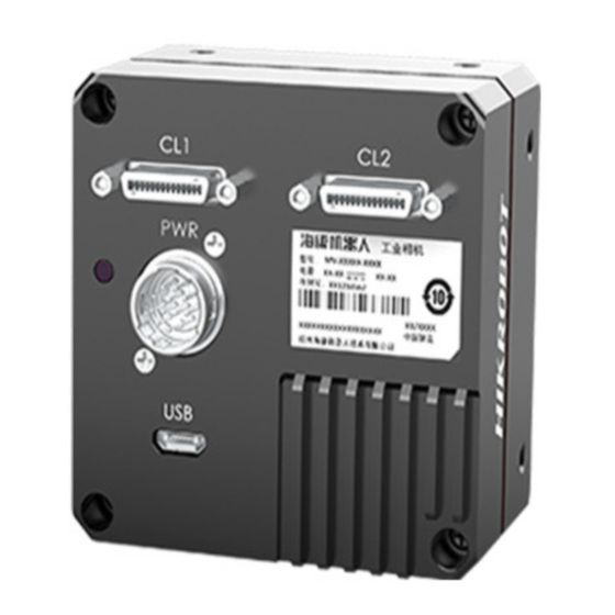
Page 11: Chapter 2 Appearance
Camera Link Line Scan Camera User Manual · Chapter 2 Appearance Appearances here are for reference only. Refer to the camera's specification for detailed dimension and other information. Figure 2-1 Appearance (Type I) Figure 2-2 Appearance (Type II) - Page 12 Camera Link Line Scan Camera User Manual · Figure 2-3 Appearance (Type III) Table 2-1 Component Description Name Description Lens Mount It is used to install lens. It is used to fix the camera to the installation position. Screw Hole ●...
- Page 13 · Refer to the table below for the relation between camera model and camera appearance type. Table 2-2 Camera Model and Appearance Type Camera Model Camera Appearance Type MV-CL042-91CM/CC Type I camera MV-CL084-90CM, MV-CL086-90CC Type II camera MV-CL086-91CC Type III camera...
-
Page 14: Chapter 3 Interface And Indicator
Camera Link Line Scan Camera User Manual · Chapter 3 Interface and Indicator 3.1 Power and I/O Interface All Camera Link line scan cameras have a 12-pin power and I/O interface, as shown below, but their pin definitions are different by camera models. Figure 3-1 12-Pin Power and I/O Interface 3.1.1 First Type of Pin Definitions Regarding type I and type III cameras, read the table below to get their pin definitions. -
Page 15: Second Type Of Pin Definitions
Camera Link Line Scan Camera User Manual · Signal I/O Signal Source Description LINE3_N Line 3- Differential input/output IO 3- LINE4_P Line 4+ Differential input/output IO 4+ LINE1_P Line 1+ Differential input/output IO 1+ LINE1_N Line 1- Differential input/output IO 1- DC_PWR DC power supply positive LINE4_N... -
Page 16: Indicator
Camera Link Line Scan Camera User Manual · Signal I/O Signal Source Description IO_OUT0_N Line 1- Differential output 0- IO_OUT1_P Line 4+ Differential output 1+ IO_OUT1_N Line 4- Differential output 1- 3.2 Indicator The indicator is used to display camera status. Table 3-3 Indicator Description Indicator Color Indicator Status... -
Page 17: Chapter 4 Camera Installation
Camera Link Line Scan Camera User Manual · Chapter 4 Camera Installation 4.1 Installation Preparation You need to prepare following accessories before camera installation. Table 4-1 Accessories Name Quantity Description Power and I/O Cable 1 It refers to the 12-pin power and I/O cable that you need to purchase separately. - Page 18 Camera Link Line Scan Camera User Manual · 3. Connect the camera to a suitable power adapter via the power and I/O cable. The camera interface for connecting Camera Link cable is SDR interface, and you need to select applicable Camera Link cable according to camera interface and frame grabber model you use, and connect camera’s Camera Link interfaces to respective interfaces of the frame grabber.
-
Page 19: Chapter 5 Camera Connection
Camera Link Line Scan Camera User Manual · Chapter 5 Camera Connection 5.1 Install Frame Grabber Software The frame grabber software is used to set frame grabber parameters, view and set camera parameters, and acquire images. Steps: 1. Get the installation package of the frame grabber software and drivers from frame grabber supplier. -
Page 20: Install Mvs Client Software
Camera Link Line Scan Camera User Manual · Table 5-2 Parameters of Matrox Frame Grabber Frame Grabber Parameters Camera Parameters Pixel Clock Frequency Pixel Clock Camera Link config Configuration Mode Taps Tap Number Device Tap Configuration Tap Geometry 5.3 Install MVS Client Software MVS client software is used to connect the camera, set its parameters, etc. -
Page 21: Connect Camera To Client Software
Camera Link Line Scan Camera User Manual · Figure 5-1 Installation Interface 4. Click Start Setup. 5. Set Options according to actual demands. 6. Finish the installation according to prompts. 5.4 Connect Camera to Client Software Steps: 1. Run the MVS client software. 2. -
Page 22: Chapter 6 Quick Started With Mvs
Camera Link Line Scan Camera User Manual · Chapter 6 Quick Started with MVS 6.1 Client Software Layout After connecting to the camera, the client software can read the camera attributes and display them. Figure 6-1 Main Window For specific main window of the client software, please refer to the actual one you got. Table 6-1 Description of Main Window Area Name Description... - Page 23 Camera Link Line Scan Camera User Manual · Area Name Description This area displays the acquisition images in real-time. You can click Display Window different icons to capture and save image, record, etc. You can view and set features of the selected camera, and perform Feature Panel operations such as importing, exporting, and saving features.
-
Page 24: Transport Layer Control
Camera Link Line Scan Camera User Manual · Attribute Description Digital IO Control You can set the different input and output signals. Counter and Timer You can view and set counter and timer related parameters. Control File Access Control You can view and set the device file access control related parameters. Transport Layer You can set the parameters of transport layer of the device. -
Page 25: Serial Port Tool
Camera Link Line Scan Camera User Manual · 6.3 Serial Port Tool Apart from the MVS client software and frame grabber software, the serial port tool can be used to detect camera status, read and set its parameters. You can set camera parameters by connecting Camera Link serial port cable. When accessing the camera or using the terminal in the application software, you are required to set the parameters as follows. - Page 26 Camera Link Line Scan Camera User Manual · Executing the reading or writing command is as follows. Table 6-5 Command for Writing or Reading Command for writing: The following example is to set the exposure as 1000 us. Command: w ExposureTime 1000 <\r> Returned value: Success! <\r>...
-
Page 27: Chapter 7 Image Acquisition
Camera Link Line Scan Camera User Manual · Chapter 7 Image Acquisition 7.1 Set Line Rate Line rate refers to the image line number that is output by the camera per second. The following 4 factors determine the maximum line rate: ... -
Page 28: Set Frame Timeout
Camera Link Line Scan Camera User Manual · Figure 7-2 Set Scan Mode 7.3 Set Frame Timeout The frame timeout function may differ by camera models. If the frame timeout function is disabled, the camera outputs one frame image after its outputted line quantity reaches the configured height value, and the camera will wait line quantity data if the outputted line quantity does not reach the configured height value. -
Page 29: Set Trigger Mode
Camera Link Line Scan Camera User Manual · 7.5 Set Trigger Mode The camera has 4 types of trigger modes, including internal trigger mode, line trigger mode, frame trigger mode, and line + frame trigger mode. Table 7-1 Trigger Mode Principle and Parameter Trigger Mode Parameter Parameter Value Principle... -
Page 30: Set Trigger Source
Camera Link Line Scan Camera User Manual · Trigger Mode Parameter Parameter Value Principle the internal configured value. Only after the frame trigger signal arrives, the line trigger signal will work. 7.6 Set Trigger Source Apart from the internal trigger mode, you need to set the trigger source for line trigger or frame trigger if their trigger signals come from external signals. -
Page 31: Set Software Trigger
Camera Link Line Scan Camera User Manual · Trigger Supported Parameter Parameter Principle Source Trigger Mode Value Frame trigger or Acquisition Anyway Use trigger sources mentioned Free Trigger line trigger Control > above to send trigger signal to the Trigger Source camera to acquire images. -
Page 32: Set Shaft Encoder Control
Camera Link Line Scan Camera User Manual · Steps: 1. Click Acquisition Control > Trigger Selector. 2. Select Line Start or Frame Burst Start as Trigger Selector, and On as Trigger Mode. 3. Select specific lines as Trigger Source according to actual demands. Figure 7-6 Set Hardware Trigger 7.6.3 Set Shaft Encoder Control If the camera enables the line trigger, you can select Encoder Module Out as trigger source. - Page 33 Camera Link Line Scan Camera User Manual · Follow steps below to set shaft encoder control. Steps: 1. Click Encoder Control, and set Encoder Source A and Encoder Source B according to actual demands. 2. Set Encoder Trigger Mode. Any Direction means that both forward and backward direction will trigger. ...
-
Page 34: Set Frequency Converter Control
Camera Link Line Scan Camera User Manual · 5. (Optional) Set Encoder Max Reverse Counter to avoid outputting images if the object moves backward accidently during measurement, and click Execute in Encoder Reverse Counter Reset to let the camera to output images again. 7.6.4 Set Frequency Converter Control If the camera enables the frame trigger or the line trigger, you can select Frequency Converter as trigger source. -
Page 35: View Trigger Line Rate
Camera Link Line Scan Camera User Manual · 4. Click Frequency Converter Control, and select specific line, Encoder Module Out or CC1/CC2/CC3/CC4 as Input Source according to actual demands. N/A means that input source is not used. 5. Set Rising Edge or Falling Edge as Signal Alignment according to actual demands. 6. -
Page 36: Set Frame Grabber Trigger Control
Camera Link Line Scan Camera User Manual · Figure 7-11 View Trigger Line Rate Make sure that line trigger is enabled and input source value of frequency converter control and trigger source value of acquisition control is the same before viewing trigger line rate. 7.6.6 Set Frame Grabber Trigger Control The specific trigger source may differ by camera models. -
Page 37: Set Free Trigger
Camera Link Line Scan Camera User Manual · Figure 7-12 Set Frame Grabber Trigger 7.6.7 Set Free Trigger If the camera enables the frame trigger or line trigger, you can select Anyway as trigger source to enable the free trigger. At this time, the camera can receive signals of all trigger sources. Steps: 1. -
Page 38: Acquisition Burst Frame Count
Camera Link Line Scan Camera User Manual · debouncer. Different trigger modes can set various trigger parameters, and their relation is shown below. If the frame trigger is enabled, the relation between trigger source and trigger related parameters is shown below. Table 7-3 Trigger Source and Trigger Related Parameters Frequency Frame... -
Page 39: Trigger Activation
Camera Link Line Scan Camera User Manual · Figure 7-14 Set Burst Frame Count When Acquisition Burst Frame Count is 1, it is in single frame trigger mode. When Acquisition Burst Frame Count is larger than 1, it is in multi-frame trigger mode. If Acquisition Burst Frame Count is n and when inputting 1 trigger signal, the camera stops acquiring images after exposing n times and outputs n frame images. - Page 40 Camera Link Line Scan Camera User Manual · Trigger Activation Parameter Parameter Value Principle Falling Edge Acquisition Control > Falling Edge The camera receives signal and Trigger Activation triggers when the level signal sent by the external device is in the falling edge.
-
Page 41: Trigger Delay
Camera Link Line Scan Camera User Manual · Figure 7-17 Level Trigger in Frame Trigger Set Trigger Activation in Line Trigger In the line trigger mode, the trigger activation is related with Exposure Mode. When Timed is selected as Exposure Mode, you can select Rising Edge, Falling Edge or Any Edge as Trigger Activation, and Exposure Auto and Exposure Time determine the exposure time. -
Page 42: Frame/Line Trigger Cache
Camera Link Line Scan Camera User Manual · Figure 7-19 Signal Delay Sequence Diagram The sequence diagram above uses rising edge as trigger activation. You can click Acquisition Control > Trigger Delay, and enter Trigger Delay. Figure 7-20 Set Trigger Delay 7.7.4 Frame/Line Trigger Cache The frame/line trigger cache function may differ by camera models. - Page 43 Camera Link Line Scan Camera User Manual · Figure 7-21 Set Trigger Cache in Frame Trigger If the camera receives the 1st trigger signal first, and the camera receives the 2nd trigger signal during processing the 1st trigger signal. Disable Trigger Cache Enable: the 2nd trigger signal will be filtered without processing. Figure 7-22 Second Frame Filtered ...
-
Page 44: Trigger Debouncer
Camera Link Line Scan Camera User Manual · Thus making sure this exposure time is not earlier than the camera’s last frame creation time of the 1st trigger signal. Figure 7-24 Sequence Diagram The three sequence diagrams above use rising edge as trigger activation, and the camera’s height parameter is 4. - Page 45 Camera Link Line Scan Camera User Manual · Figure 7-26 Trigger Debouncer Sequence Diagram Click Digital IO Control > Line Debouncer Time, and set Line Debouncer Time according to actual demands. Figure 7-27 Set Line Debouncer Time When the configured debouncer time is larger than trigger signal time, and the trigger signal will be ignored.
-
Page 46: Chapter 8 I/O Output
Camera Link Line Scan Camera User Manual · Chapter 8 I/O Output 8.1 Select Output Signal The selectable output signal line may differ by camera models. Type I and Type III Cameras Type I and type III cameras has four signal lines (Line 0/1/3/4) that can be set as input or output, and you can set them as output as shown below. -
Page 47: Set Output Signal
Camera Link Line Scan Camera User Manual · Figure 8-2 Select Output Signal (Type II Camera) 8.2 Set Output Signal The output signal of the camera is switch signal, which is used to control external devices such as alarm light, light source and PLC. There are two ways to achieve output signal, including line inverter and strobe signal. - Page 48 Camera Link Line Scan Camera User Manual · The event source may differ by camera models. The strobe signal is used to directly output signal to external devices when the camera’s event source occurs. When selected event sources occur, one event information will be created, and the camera will output one strobe signal at the same time.
- Page 49 Camera Link Line Scan Camera User Manual · Parameter Read/Write Description Counter Reset Source Read and write It selects the signal source of resetting counter. Software is available only. It is disabled by default. Counter Reset Write is available It resets counter and it can be executed when under certain selecting Software as Counter Reset Source.
- Page 50 Camera Link Line Scan Camera User Manual · Figure 8-5 Set Frame Mode If you need to let the camera output signals when event sources occur that are corresponding to each line image, follow steps below to set it. Steps: 1.
- Page 51 Camera Link Line Scan Camera User Manual · Set Strobe Line Duration After enabling strobe signal, you can set its duration. Click Digital IO Control > Strobe Line Duration, and enter Strobe Line Duration. Figure 8-7 Set Strobe Line Duration When the Strobe Line Duration value is 0, the strobe duration is equal to the exposure time.
- Page 52 Camera Link Line Scan Camera User Manual · Figure 8-9 Sequence Diagram of Strobe Line Delay The camera’s height parameter is 4 in the sequence diagram above. Set Strobe Line Pre Delay The camera also supports the function of strobe line pre delay, which means that the strobe signal takes effect early than exposure.
- Page 53 Camera Link Line Scan Camera User Manual · Figure 8-11 Sequence Diagram of Strobe Line Pre Delay The camera’s height parameter is 4 in the sequence diagram above.
-
Page 54: Chapter 9 I/O Electrical Feature And Wiring
Camera Link Line Scan Camera User Manual · Chapter 9 I/O Electrical Feature and Wiring 9.1 I/O Introduction The I/O signals of type I and type III cameras are four configurable input or output signals (Line 0/1/3/4). The Line 0/1/3/4 can be set as differential input or differential output according to actual demands. -
Page 55: Differential Output Circuit
Camera Link Line Scan Camera User Manual · receiver and the bus should be as short as possible. The bus must have a 120 Ω terminal resistance. When the camera is the last receiver on the bus structure, the camera's terminal resistance needs to be enabled, and the rest camera's terminal resistance need to be disabled. -
Page 56: Input Wiring For Type I And Type Iii Cameras
Camera Link Line Scan Camera User Manual · RS-644 Standard Output The camera adopting RS-422 standard output signal cannot directly connect to RS-644 standard. When connecting RS-644 standard output, it is required to add a resistance network in camera’s output location. - Page 57 Camera Link Line Scan Camera User Manual · Signal Source Power Camera Power PNP Single- Hang Line*P Ended Signal Line*N Signal Line Source Signal Source Power Ground Camera Power Ground Figure 9-4 PNP Single-Ended Input Wiring without Pull-Down Resistor Signal Source Power Camera Power Line*_P PNP Single-...
-
Page 58: Output Wiring For Type I And Type Iii Cameras
Camera Link Line Scan Camera User Manual · 9.4 Output Wiring for Type I and Type III Cameras The I/O signal of type I and type III cameras can be configured as output to trigger other devices. Here we take the type I camera as an example for introducing the output wiring. 9.4.1 Differential Output Singal If the camera’s I/O signal is set as the differential output signal, and the wiring is shown below. -
Page 59: Input Wiring For Type Ii Camera
Camera Link Line Scan Camera User Manual · Camera Power Line*P Signal Line Triggered Device Hang Line*N Triggered Device Camera Power Ground Power Ground Figure 9-9 Single-Ended Output Wiring with Pull-Up Resistor The voltage of the VCC should be matched with the trigger voltage. 9.5 Input Wiring for Type II Camera Type II camera receives input signals via Line 0/3 to trigger and acquire images. -
Page 60: Single-Ended Signal
Camera Link Line Scan Camera User Manual · Camera Power Signal Source Power Differential Input Positive OUT A Differential OUT Ã Signal Differential Input Negative Source Camera Power Ground Figure 9-11 12 V and 24 V Differential Signal Sources Output Differential Signal With different voltages of differential signal sources, the respective resistance values in wiring are also different, as shown below. -
Page 61: Line Trigger Wiring
Camera Link Line Scan Camera User Manual · PNP Single-Ended Signal Source When the PNP single-ended signal source provides signal, and the camera’s differential input is used as single-ended input. The VCC of PNP single-ended signal source is 5 V, 12 V or 24 V. Signal Source Power Camera Power Differential Input Positive... -
Page 62: Frame Trigger Wiring
Camera Link Line Scan Camera User Manual · VCC=5 V Encoder Power Camera Power Differential Input 0 Positive OUT A Differential Input 0 Negative Encoder OUT Ã Signal Differential Input 1 Positive OUT O Differential Input 1 Negative OUT Õ Camera Power Ground Encoder Power Ground Figure 9-15 Line Trigger Wiring... - Page 63 Camera Link Line Scan Camera User Manual · Encoder Power Camera Power Differential Input 0 Positive OUT A Differential Input 0 Negative Encoder OUT Ã Signal Differential Input 1 Positive OUT O Differential Input 1 Negative OUT Õ Camera Power Ground Encoder Power Ground Figure 9-17 Line + Frame Trigger Wiring (I) The wiring of using the frame grabber to have a frame trigger and using 12 V or 24 V encoder...
- Page 64 Camera Link Line Scan Camera User Manual · 12 V or 24 V Encoder Power Camera Power Differential Input 0 Positive OUT A Differential Input 0 Negative Encoder Hang Signal Differential Input 1 Positive OUT O Differential Input 1 Negative Hang Encoder Power Ground Camera Power Ground...
-
Page 65: Chapter 10 Image Parameter
Camera Link Line Scan Camera User Manual · Chapter 10 Image Parameter 10.1 View Resolution Click Image Format Control, and view Width Max and Height Max. Width Max stands for the max. pixels per inch in width direction and Height Max stands for the max. pixels per inch in height direction. -
Page 66: Set Image Reverse
Camera Link Line Scan Camera User Manual · Figure 10-2 Set ROI 10.3 Set Image Reverse The camera supports horizontal reverse image output. You can click Image Format Control, and enable Reverse X according to actual demands. Figure 10-3 Set Image Reverse For different models of cameras, the image reverse function may differ, and the actual product you purchased shall prevail. -
Page 67: Set Pixel Format
Camera Link Line Scan Camera User Manual · 10.4 Set Pixel Format The camera supports many pixel formats. For specific pixel formats that the camera supports, please refer to the specifications of the camera. The default output data format of color camera is RGB, and the default output data format of mono camera is Mono 8. - Page 68 Camera Link Line Scan Camera User Manual · By default, the test pattern is Off. For different models of cameras, the test pattern may differ, and the actual product you purchased shall prevail. Click Image Format Control > Test Pattern, and set Test Pattern according to actual demands. Figure 10-5 Test Pattern of Mono Camera The mono camera offers 4 test patterns, including Mono Bar, Checkboard, Oblique Mono Bar and Gradual Mono Bar.
-
Page 69: Set Binning
Camera Link Line Scan Camera User Manual · Figure 10-10 Vertical Color Bar Test Pattern Figure 10-11 Horizontal Color Bar Test Pattern 10.6 Set Binning The binning function may differ by camera models. The purpose of setting binning is to enhance sensibility. With binning, multiple sensor pixels are combined as a single pixel to reduce resolution and improve image brightness. -
Page 70: Set Gain
Camera Link Line Scan Camera User Manual · Table 10-2 Exposure Method and Principle Exposure Method Principle The camera exposures according to the value configured by user in Exposure Time. Once Adjust the exposure time automatically according to the image brightness. After adjusting, it will switch to Off Mode. Continuous Adjust the exposure time continuously according to the image brightness. -
Page 71: Set Analog Gain
Camera Link Line Scan Camera User Manual · 10.8.1 Set Analog Gain For different models of the camera, the analog gain range may be different, please refer to the actual one you got. Click Analog Control > Preamp Gain, and select Preamp Gain according to actual demands. Figure 10-14 Set Analog Gain 10.8.2 Set Digital Gain Apart from analog gain, the camera also supports digital gain function. -
Page 72: Set Black Level
Camera Link Line Scan Camera User Manual · Figure 10-16 Set Brightness After setting brightness, the camera will automatically adjust exposure time to let image brightness reach target one. Under Once or Continuous exposure mode, or Once or Continuous gain, the higher the brightness value, the brighter the image will be. - Page 73 Camera Link Line Scan Camera User Manual · Click Analog Control > Balance White Auto, and select Balance White Auto according to actual demands. Table 10-3 White Balance Status Description White Balance Description Mode You need to set the R, G, B value manually, between 1 and 4095.
-
Page 74: Set Gamma Correction
Camera Link Line Scan Camera User Manual · 2. Find corresponding R/G/B channel in Balance Ratio Selector. Here we take Green as an example. 3. Find camera’s R/G/B value. 4. Take Green as correction standard, and manually adjust other two channels (R channel and B channel) to let these three channels have same value. -
Page 75: Set Aoi
Camera Link Line Scan Camera User Manual · Steps: 1. Click Analog Control > Gamma Selector. 2. Select User as Gamma Selector. 3. Enable Gamma Enable. 4. Enter Gamma according to actual demands, and its range is from 0 to 4. Figure 10-20 Set User Mode You can set sRGB mode as shown below. -
Page 76: Set Color Transformation Control
Camera Link Line Scan Camera User Manual · AOI1 1 is used to adjust the image brightness, and AOI 2 is used to adjust the white balance for color cameras. 2. Enter Auto Function AOI Width, Auto Function AOI Height, Auto Function AOI Offset X, and Auto Function AOI Offset Y according to actual demands. -
Page 77: Set Hue
Camera Link Line Scan Camera User Manual · Figure 10-23 Method 1 Method 2 Steps: 1. Click Color Transformation Control, and enable CCM Enable. 2. Enable Color Transformation Enable. 3. Set Hue and Saturation to adjust Color Transformation Value. Figure 10-24 Method 2 10.15 Set Hue ... -
Page 78: Set Saturation
Camera Link Line Scan Camera User Manual · Steps: 1. Click Color Transformation Control, and enable CCM Enable. 2. Enable Color Transformation Enable. 3. Enable Hue Enable, and enter Hue according to actual demands. Figure 10-25 Set Hue 10.16 Set Saturation ... -
Page 79: Set Super Palette Control
Camera Link Line Scan Camera User Manual · Figure 10-26 Set Saturation 10.17 Set Super Palette Control This function may differ by camera models. The mono and bayer pixel formats do not support this function The super palette control function allows you to select different color areas in the image to set customized hue and saturation values. -
Page 80: Set Flat Field Correction
Camera Link Line Scan Camera User Manual · You cannot use Gamma correction function and LUT function at the same time. After using the TDI function, you need to set LUT again. Refer to section File Access Control for exporting and importing LUT device feature. Steps: 1. - Page 81 Camera Link Line Scan Camera User Manual · 2. Click Execute in Activate Shading, and enable FPNC User Enable. Figure 10-29 FPNC Correction PRNUC Correction Steps: 1. Click Shading Correction, and select PRNUC Correction as Shading Selector. 2. Select PRNUC User Selector according to actual demands. 3.
- Page 82 Camera Link Line Scan Camera User Manual · Figure 10-30 PRNUC Correction The effect of PRNUC correction is shown blow. Figure 10-31 Before PRNUC Correction...
-
Page 83: Set Space Correction
Camera Link Line Scan Camera User Manual · Figure 10-32 After PRNUC Correction If you want to use PRNUC correction function for specific areas, set PRNUC Width and PRNUC Offset X according to actual demands, and enable PRNUC ROI Enable. Figure 10-33 Set PRNUC Width and Offset X 10.20 Set Space Correction The space correction function may differ by camera models. - Page 84 Camera Link Line Scan Camera User Manual · It is recommended to set line rate ratio as 1 when the camera’s line rate is equal to that of the object. The line rate ratio function is valid only when the camera is in TDI mode. Figure 10-34 Set Line Rate Ratio ...
-
Page 85: Set Color Abnormal Correction
Camera Link Line Scan Camera User Manual · Figure 10-35 Set Parallax Direction and Pixel Shift 10.21 Set Color Abnormal Correction The color abnormal correction function may differ by camera models. The color abnormal correction (CAC) is used to eliminate abnormal color on image edges. Steps: 1. -
Page 86: Chapter 11 Other Functions
Camera Link Line Scan Camera User Manual · Chapter 11 Other Functions 11.1 Device Control In the Device Control attribute, you can view device information, edit device name, etc. Table 11-1 Device Control Parameter Description Parameter Read/Write Description Device Scan Type Read only It is the scan type of the sensor. -
Page 87: Tdi Function
Camera Link Line Scan Camera User Manual · Parameter Read/Write Description It is the period of time when device is powered Device Uptime(s) Read only Board Device Type Read only It is the device type. Device Command Read only It counts the timeout of command. Timeout Device Reset Write only... -
Page 88: Reverse Scan Function
Camera Link Line Scan Camera User Manual · Go to Image Format Control > TDI Mode, and set TDI Mode according to actual demands. Figure 11-1 Set TDI Mode 11.3 Reverse Scan Function The reverse scan function may differ by camera models. ... -
Page 89: File Access Control
Camera Link Line Scan Camera User Manual · 11.4 File Access Control The file access function allows you to export or import the camera’s parameters, LUT and user PRNUC, and user FPNC in the mfa format. Currently, the camera supports User Set 1/2/3, LUT Luminance 1/2/3, User PRNUC 1/2/3, and User FPNC. -
Page 90: Transport Layer Control
Camera Link Line Scan Camera User Manual · The camera has different process approaches when you select different device features. If User Set 1/2/3 is selected as device feature, you need to load the corresponding user set you selected to take effect. Refer to section Save and Load User Set for details. ... - Page 91 Camera Link Line Scan Camera User Manual · When Device Tap Geometry is Geometry_1X, the output order of tap is shown below. Figure 11-6 Geometry_1X When Device Tap Geometry is Geometry_1X2 the output order of tap is shown below. Figure 11-7 Geometry_1X2 When Device Tap Geometry is Geometry_1X4, the output order of tap is shown below.
-
Page 92: Save And Load User Set
Camera Link Line Scan Camera User Manual · 11.6 Save and Load User Set The camera supports 4 sets of parameters, including 1 default set and 3 user sets. The relation among 4 sets of parameters is shown below. Figure 11-9 Parameter Relation You can save parameters, load parameters and set user default as shown below. -
Page 93: Update Firmware
Camera Link Line Scan Camera User Manual · Figure 11-11 Load User Set Loading parameters is available when connecting with camera, but without live view. Set User Default You can also set default parameter by selecting parameter from drop-down list of User Set Default, as shown below. - Page 94 Camera Link Line Scan Camera User Manual · Please use the firmware package of the corresponding camera model for updating. Update Firmware via Camera Link Cable Steps: 1. Click Tool > Firmware Updater to open the update interface. 2. Click to select the camera.
- Page 95 Camera Link Line Scan Camera User Manual · Figure 11-14 Update Firmware via USB Data Cable...
-
Page 96: Chapter 12 Trouble Shooting
Camera Link Line Scan Camera User Manual · Chapter 12 Trouble Shooting Table 12-1 Trouble Shooting No. Trouble Possible Reason Solution Check camera power wiring (observe No camera found when Camera is not started up running the client. normally, or Camera Link the LED indicator). -
Page 97: Chapter 13 Revision History
Camera Link Line Scan Camera User Manual · Chapter 13 Revision History Table 13-1 Revision History Version No. Document No. Date Revision Details Modify section Appearance. V2.0.6 UD25427B Sep. 8, 2021 Modify section Interface and Indicator. Modify section Client Software Layout. ... - Page 98 Camera Link Line Scan Camera User Manual · Add section Set Free Trigger. Modify section Trigger Related Parameters. Modify section Trigger Activation. Modify section Frame/Line Trigger Cache. Modify section Enable Strobe Signal. Add section I/O Introduction. ...
-
Page 99: Appendix Serial Communication Command List
Camera Link Line Scan Camera User Manual · Appendix Serial Communication Command List The commands listed below are common ones only. For other commands, please contact technical support personnel via e-mail: tech_support@hikrobotics.com for detailed information. Table Appendix-1 Command List Parameter Command Value Description... - Page 100 Camera Link Line Scan Camera User Manual · Parameter Command Value Description r OffsetY Read vertical offset from the origin to the region of interest (in pixels). Reverse X w ReverseX x Set image reverse X. 0—disable E.g., w ReverseX 1. 1—enable r ReverseX Read image reverse X.
- Page 101 Camera Link Line Scan Camera User Manual · Parameter Command Value Description 16—GradualMonoBar Read test pattern. r TestPattern Binning w Binning X 0x20004 (2 stands for Read combined pixel vertical and 4 stands number. for horizontal) r Binning X Set combined pixel number.
- Page 102 Camera Link Line Scan Camera User Manual · Parameter Command Value Description Read final (actual) line Resulting r ResultingLineRate rate. LineRate x=read value Read final (actual) line ResultingFrameRate r ResultingFrameRate rate. y=value shown in MVS y= x/10000 ScanMode w ScanMode x Select frame scan mode or line scan mode.
- Page 103 Camera Link Line Scan Camera User Manual · Parameter Command Value Description TriggerSource w TriggerSource+6 x Set the frame trigger source 7—software (frame trigger supported E.g., w TriggerSource+6 7. only) 0—Line0 1—Line1 3—Line3 5—Line4 6—EncoderModuleOu w TriggerSource+9 x Set the line trigger source (line trigger E.g., w TriggerSource+9 3.
- Page 104 Camera Link Line Scan Camera User Manual · Parameter Command Value Description 65—On r TriggerCacheEnable Read trigger cache status. ExposureAuto w ExposureAuto 1—once Set the auto exposure. E.g., w ExposureAuto 2. 2—auto 0—off r ExposureAuto 1—once Read the exposure mode. 2—auto 0—off ExposureTime...
- Page 105 Camera Link Line Scan Camera User Manual · Parameter Command Value Description 1—enable FrameTimeoutEnable 0. Read frame timeout r FrameTimeoutEnable enable. AbnormalLineEnabl 0—disable Enable abnormal line w AbnormalLineEnable 1 function. 1—enable PreampGain Set gain value. w PreampGain x Gain multiple value x E.g., w PreampGain 2700 1000 (set the gain as 2.7 x)
- Page 106 Camera Link Line Scan Camera User Manual · Parameter Command Value Description Read black level. r BlackLevel BlackLevelEnable Set black level enable. w BlackLevelCtrl x 0—disable E.g., w BlackLevelCtrl 1. 1—enable Read black level enable. r BlackLevelCtrl GammaAbsVal w GammaAbsVal x: game value Set Gama value, and x×100+y...
- Page 107 Camera Link Line Scan Camera User Manual · Parameter Command Value Description x: 0 Set the start columnof AutoFunctionAOIOff w AutoAOIOffsetX x auto function AOI. E.g., w setX AutoAOIOffsetX 0. r AutoAOIOffsetX x: 0-4760 Set the start row of auto AutoFunctionAOIOff w AutoAOIOffsetY x function AOI.
- Page 108 Camera Link Line Scan Camera User Manual · Parameter Command Value Description ColorTransformationValu selected Gain factor or Offset inside the Transformation matrix. x: 0-255 Set hue. E.g., w HueAbsVal HueAbsVal w HueAbsVal x 128. Read hue. r HueAbsVal Enable hue or not. E.g., w HueCtrl w HueCtrl x HueCtrl 0x1000000.
- Page 109 Camera Link Line Scan Camera User Manual · Parameter Command Value Description Save selected LUT. E.g., w LUTSave w LUT Save x LUT Save 1 1—save Set encoder source A. Eg: Encoder Source A w EncoderSourceA x w EncoderSourceA 3. 0—Line0 3—Line3 Read encoder source A.
- Page 110 Camera Link Line Scan Camera User Manual · Parameter Command Value Description er 1. Read encoder max. reverse counter. EncoderMaxReverseCou nter x: 1 Reset encoder reverse Encoder Reverse counter. Eg: w Counter Reset EncoderReverseCounterR EncoderReverseCounterRe eset x set 1. Set input source. Input Source w InputSource x 0—Line0...
- Page 111 Camera Link Line Scan Camera User Manual · Parameter Command Value Description Resulting Trigger It refers to the external Line Rate (Hz) trigger frequency cameras ResultingTriggerLin received after the external eRate trigger raw line rate is calculated via frequency converter control. It only involves external trigger signals.
- Page 112 Camera Link Line Scan Camera User Manual · Parameter Command Value Description Enable PRNUC’s user set. PRNUCUserEnable w PRNUCUserEnable x E.g., w PRNUCUserEnable 0—disable 1—enable Read PRNUC’s user set. r PRNUCUserEnable Select PRNUC’s user set. PRNUCUserSelector w PRNUCUserSelector x E.g., w 0—UserPRNUC1 PRNUCUserSelector 0.
- Page 113 Camera Link Line Scan Camera User Manual · Parameter Command Value Description x=y*1024 Read pixel shift. r PixelShift Set the direction of ParallaxDirection w ParallaxDirection x parallax. E.g., w 0—Off ParallaxDirection 0. 1—Red 2—Blue Read the direction of r ParallaxDirection parallax.
- Page 114 Camera Link Line Scan Camera User Manual · Parameter Command Value Description Read LineInverter status. r LineInverter LineStatusAll r LineStatusAll Camera input/output Read the status of signal status: 1 level LineStatusAll high, 0 level low. Input: bit [7:0] Bit[0]: line0 input Bit[1]: line3 input Bit[2]: line6 input Bit[3]: line9 input...
- Page 115 Camera Link Line Scan Camera User Manual · Parameter Command Value Description Bit[25]: line5 output Bit[26]: line8 output Bit[27]: line11 output LineSource w LineSource+ x y Selects which internal acquisition or I/O source 1—Line1 signal to output on the 3—Line3 selected Line.
- Page 116 Camera Link Line Scan Camera User Manual · Parameter Command Value Description y: 0—10000 and the unit is μs. E.g., w StrobeLineDuration +3 200. r StrobeLineDelay+ x Read the delay of strobe. StrobeLinePreDelay w StrobeLinePreDelay+ x x: 3—Line3 Set the value of strobe line pre-delay, and the unit is y: 0—50000 μs.
- Page 117 Camera Link Line Scan Camera User Manual · Parameter Command Value Description 0—read the device. E.g., set read mode, w FileOpenMode 0 1—write Read r FileOpenMode FileOperationSelector on the selected file. Provides the number of PayloadSize r PayloadSize bytes transferred for each data buffer or chunk on the stream channel.
- Page 118 Camera Link Line Scan Camera User Manual · Parameter Command Value Description Range 0 to 255. SuperPaletteSaturati SuperPaletteSaturation+ 0 128 CACEnable w CACEnable 1 Range 0 to 2040. CACEdgeThreshold w CACEdgeThreshold DeviceTapGeometry w DeviceTapGeometry x Set the camera’s transmission mode. Eg: w 0x01020181 DeviceTapGeometry Geometry_1X2...
- Page 119 Camera Link Line Scan Camera User Manual · Parameter Command Value Description 2—userset2 3—userset3 r UserSetSelector Read selected user parameter. 0—default 1—userset1 2—userset2 3—userset3 UserSetLoad w UserSetLoad 1 Execute Load UserSetDefault parameter. UserSetSave w UserSetSave 1 Execute Save parameters setting to UserSetSelector.
- Page 120 UD25427B...
Need help?
Do you have a question about the MV-CL042-91CM and is the answer not in the manual?
Questions and answers