Table of Contents
Advertisement
Advertisement
Table of Contents

Related Manuals for HikRobot SC5000 Series


Summary of Contents for HikRobot SC5000 Series
- Page 1 SC5000 Series Smart Camera Quick Start Guide...
- Page 2 INTERRUPTION, OR LOSS OF DATA, CORRUPTION OF SYSTEMS, OR LOSS OF DOCUMENTATION, WHETHER BASED ON BREACH OF CONTRACT, TORT (INCLUDING NEGLIGENCE), PRODUCT LIABILITY, OR OTHERWISE, IN CONNECTION WITH THE USE OF THE PRODUCT, EVEN IF HIKROBOT HAS BEEN ADVISED OF THE POSSIBILITY OF SUCH DAMAGES OR LOSS.
- Page 3 SC5000 Series Smart Camera Quick Start Guide THE PERFORMANCE DATA IN THIS PUBLICATION IS BASED ON HIKROBOT'S INTERNAL RESEARCH/EVALUATION. ACTUAL DATA MAY VARY DEPENDING ON SPECIFIC CONFIGURATIONS AND OPERATING CONDITIONS AND HIKROBOT SHALL NOT BEAR THE CONSEQUENCES ARISING THEREFROM. IN THE EVENT OF ANY CONFLICTS BETWEEN THIS MANUAL AND THE APPLICABLE LAW, THE LATTER PREVAILS.
- Page 4 Note important points of the main text. Available Model This manual is applicable to the SC5000 Series Smart Camera. Safety Instruction These instructions are intended to ensure that the user can use the device correctly to avoid danger or property loss.
- Page 5 SC5000 Series Smart Camera Quick Start Guide immediately, unplug the power cord, and contact the service center in time. ● To reduce the risk of fire or electric shock, do not expose the device to rain or moisture. ● If the device does not work properly, please contact your dealer or the nearest service center.
- Page 6 SC5000 Series Smart Camera Quick Start Guide components, etc. must share the same ground. ● If the device is powered on and off frequently, it is necessary to strengthen the voltage isolation, and consider adding a DC/DC isolation power supply module between the device and the adapter.
-
Page 7: Table Of Contents
SC5000 Series Smart Camera Quick Start Guide Contents Chapter 1 Overview ..........................1 1.1 Introduction ........................... 1 1.2 Key Feature ..........................1 Chapter 2 Appearance ......................... 2 Chapter 3 12-Pin Interface and Indicator ................... 4 3.1 12-Pin Interface ........................4 3.2 Indicator .......................... - Page 8 SC5000 Series Smart Camera Quick Start Guide 8.3 Why the image is very dark? ....................21 8.4 Why there is no image in live view? ................... 21 8.5 What can I do if I forget the login password? ..............22...
-
Page 9: Chapter 1 Overview
Chapter 1 Overview 1.1 Introduction SC5000 series smart camera uses the sensor and optical components to acquire images, and adopts built-in vision algorithms, logic controls, and vision detection functions. It can be easily configured and operated via the SCMVS client software, and it uses multiple communication methods to output vision tool results and customized results. -
Page 10: Chapter 2 Appearance
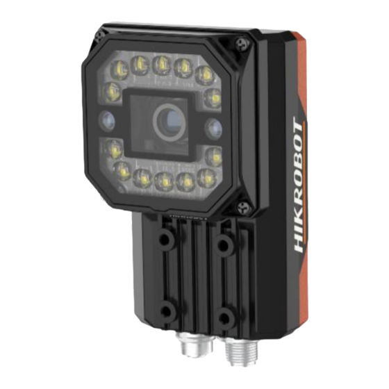
SC5000 Series Smart Camera Quick Start Guide Chapter 2 Appearance Note Appearance here is for reference only. Refer to the device's specification for detailed dimension information. Figure 2-1 Appearance (Type I) Figure 2-2 Appearance (Type II) - Page 11 SC5000 Series Smart Camera Quick Start Guide Table 2-1 Component Description Name Description Lens Cap It can be replaced with other lens cap. It is used to fix the device to the installation position. It is recommended Screw Hole to use supplied M4 screws.
-
Page 12: Chapter 3 12-Pin Interface And Indicator
SC5000 Series Smart Camera Quick Start Guide Chapter 3 12-Pin Interface and Indicator 3.1 12-Pin Interface Read the following section to get definitions of 12-pin M12 interface. Figure 3-1 12-Pin M12 Interface Table 3-1 Pin Definitions Signal I/O Signal Source... -
Page 13: Indicator
SC5000 Series Smart Camera Quick Start Guide Note You should refer to the table above and the label attached to the power and I/O cable to wire the device. 3.2 Indicator The device has five indicators, including PWR, LNK, ACK, U1 and U2 indicators. Read following sections to get the indicator status of the device. -
Page 14: Chapter 4 Installation
SC5000 Series Smart Camera Quick Start Guide Chapter 4 Installation 4.1 Installation Preparation You need to prepare following accessories before installation. Table 4-1 Accessories Name Quantity Description Some models of the device do not have lens. You need to Lens purchase lens separately. - Page 15 SC5000 Series Smart Camera Quick Start Guide Figure 4-1 Rear Installation Figure 4-2 Front Installation 3. Use the GigE network cable with RJ45 aviation connector to connect the device to a switch or a network interface card. Figure 4-3 Network Cable Wiring...
- Page 16 SC5000 Series Smart Camera Quick Start Guide 4. Use the power and I/O cable to connect the device to a DC switch power supply. Figure 4-4 Power and I/O Wiring...
-
Page 17: Chapter 5 Device Connection
SC5000 Series Smart Camera Quick Start Guide Chapter 5 Device Connection Device connection to the client software is required for device’s configuration and remote operations. This section introduces how to install the client software, set PC and device network, connect the device to the client software, etc. -
Page 18: Install Client Software
SC5000 Series Smart Camera Quick Start Guide Note It is recommended to use the static IP address to reduce time for searching the device. 3. Set NIC property. 1) Go to NIC settings page: Control Panel → Hardware and Sound → Device Manager →... -
Page 19: Set Device Network
SC5000 Series Smart Camera Quick Start Guide 5.3 Set Device Network You can set and operate the device in the client software only when the device is in the same network segment with the PC where the client software is installed. - Page 20 SC5000 Series Smart Camera Quick Start Guide Steps 1. Click the device in the device list. 2. Enter password. 3. Click to log in. Figure 5-4 Login Interface 4. (Optional) Check Remember me to remember the password if necessary. Note If you forget password, click Forgot Password in the login interface to view the device’s serial No.,...
-
Page 21: Chapter 6 Client Layout And Operation Flow
SC5000 Series Smart Camera Quick Start Guide Chapter 6 Client Layout and Operation Flow 6.1 Main Window Introduction After logging into the client software, you can see the main window as shown below. Figure 6-1 Main Window Note ● The specific interfaces of the client software may differ by its versions. -
Page 22: Operation Flow
SC5000 Series Smart Camera Quick Start Guide Name Description This area displays operation results of vision tools loaded in projects in real Tool Display Area time. You can click to view specific operation results. This area displays images and results under camera mode and image mode Live View Window in real time. -
Page 23: Chapter 7 Electrical Feature And I/O Wiring
SC5000 Series Smart Camera Quick Start Guide Chapter 7 Electrical Feature and I/O Wiring The device has three opto-isolated inputs (Line 0/1/2), three opto-isolated output (Line 3/4/5), and one RS-232 serial port. 7.1 Input Signal The device's Line 0/1/2 is opto-isolated input, and their internal circuit is as follows. -
Page 24: Output Signal
SC5000 Series Smart Camera Quick Start Guide Table 7-1 Input Electrical Feature Parameter Name Parameter Symbol Value Input Logic Level Low 1.5 VDC Input Logic Level High 2 VDC Input Falling Delay 81.6 μs Input Rising Delay 7 μs 7.2 Output Signal The device's Line 3/4/5 is opto-isolated output, and their internal circuit is as follows. -
Page 25: Input Signal Wiring
SC5000 Series Smart Camera Quick Start Guide Table 7-2 Output Electrical Feature Parameter Name Parameter Symbol Value Output Logic Level Low 730 mV Output Logic Level High 3.2 VDC Output Falling Delay 6.3 μs Output Rising Delay 68 μs Output Falling Time 3 μs... -
Page 26: Output Signal Wiring
SC5000 Series Smart Camera Quick Start Guide Device Power Input Signal NPN Device Power ● Ground Device Opto-Isolated Input Signal Line Device Power Ground NPN Power Ground GND of PWR GND of VCC Figure 7-6 Input Signal Connecting to NPN Device without Pull-Up Resistor If the VCC of NPN device is 12 VDC or 24 VDC and 1 KΩ... -
Page 27: Rs-232 Serial Port
SC5000 Series Smart Camera Quick Start Guide NPN Device If the VCC of NPN device is 12 VDC or 24 VDC and pull-up resistor is not used, its wiring is as follows. Device Power Output Signal NPN Device Power ●... -
Page 28: Rs-232 Serial Port Wiring
SC5000 Series Smart Camera Quick Start Guide Figure 7-12 25-Pin Male Connector Table 7-3 Pin Definitions Serial Port Type Pin No. Name Function Receive data 9-Pin Male Connector Send data Signal ground Send data 25-Pin Male Connector Receive data Signal ground 7.5.2 RS-232 Serial Port Wiring... -
Page 29: Chapter 8 Faq (Frequently Asked Question)
SC5000 Series Smart Camera Quick Start Guide Chapter 8 FAQ (Frequently Asked Question) 8.1 Why the client software cannot list devices? Reason ● Device is not started up normally. ● Network connection exception occurs. Solution ● Check device power wiring (observe PWR indicator). - Page 30 SC5000 Series Smart Camera Quick Start Guide Solution Send trigger signal to the device, or disable trigger mode. 8.5 What can I do if I forget the login password? Solution Click Forgot Password in the login interface to view the device serial No., and mail it to the technical support personnel or call them to get the corresponding resetting file.
- Page 31 UD26897B...
Need help?
Do you have a question about the SC5000 Series and is the answer not in the manual?
Questions and answers