Table of Contents
Advertisement
Quick Links
Advertisement
Table of Contents

Related Manuals for HikRobot CoaXPress


Summary of Contents for HikRobot CoaXPress
- Page 1 CoaXPress Area Scan Camera User Manual...
- Page 2 WITHOUT LIMITATION, MERCHANTABILITY, SATISFACTORY QUALITY, OR FITNESS FOR A PARTICULAR PURPOSE. THE USE OF THE PRODUCT BY YOU IS AT YOUR OWN RISK. IN NO EVENT WILL HIKROBOT BE LIABLE TO YOU FOR ANY SPECIAL, CONSEQUENTIAL, INCIDENTAL, OR INDIRECT DAMAGES,...
- Page 3 TO ANY NUCLEAR EXPLOSIVE OR UNSAFE NUCLEAR FUEL-CYCLE, OR IN SUPPORT OF HUMAN RIGHTS ABUSES. THE PERFORMANCE DATA IN THIS PUBLICATION IS BASED ON HIKROBOT'S INTERNAL RESEARCH/EVALUATION. ACTUAL DATA MAY VARY DEPENDING ON SPECIFIC CONFIGURATIONS AND OPERATING CONDITIONS AND HIKROBOT SHALL NOT BEAR THE CONSEQUENCES ARISING THEREFROM.
- Page 4 Indicates a hazard with a high level of risk, which if not avoided, will result in death or serious injury. Available Model This manual is applicable to the CoaXPress area scan camera. Safety Instructions These instructions are intended to ensure that the user can use the device correctly to avoid danger or property loss.
- Page 5 CoaXPress Area Scan Camera User Manual · Power Supply When wiring or dismounting, make sure that the device power is cut off, and do not operate under electrification. Avoid contact with exposed circuit. When the device is powered on, avoid contact with exposed junctions and parts.
- Page 6 CoaXPress Area Scan Camera User Manual · must be taken. Put electrostatic sensitive components into anti-static bags for protection. It is suggested to place humidifier in dry environment to maintain suitable humidity and reduce static electricity generation. Maintenance ...
-
Page 7: Table Of Contents
3.1.2 Second Type of Pin Definitions .................. 6 3.2 Indicator Description ......................6 3.2.1 Camera Indicator Status .................... 6 3.2.2 CoaXPress Linking Indicator Status ................7 Chapter 4 Installation .......................... 9 4.1 Installation Preparation ...................... 9 4.2 Install Camera and Connect Frame Grabber ..............9 Chapter 5 Camera Connection ...................... - Page 8 CoaXPress Area Scan Camera User Manual · 8.4.4 Set Counter Trigger....................23 8.4.5 Set Link Trigger ......................25 8.4.6 Set Free Trigger ....................... 26 8.5 Trigger Related Parameters ....................26 8.5.1 Set Burst Frame Count .................... 27 8.5.2 Set Trigger Delay...................... 28 8.5.3 Set Trigger Cache Enable ..................
- Page 9 12.2 File Access Control ......................75 12.3 Save and Load User Set ....................76 12.4 Transport Layer Control ....................78 12.5 CoaXPress Parameters ....................78 12.6 Update Firmware......................80 Chapter 13 FAQ ..........................82 13.1 Why the client software is stuck when listing cameras?..........82 13.2 Why the client software turns to the blue screen?............
- Page 10 CoaXPress Area Scan Camera User Manual · Appendix A Camera Parameter Index ....................85...
-
Page 11: Chapter 1 Overview
· Chapter 1 Overview 1.1 Introduction The CoaXPress (CXP) area scan camera uses CoaXPress interface to transmit non-compressed images in real time, and it acquires images and sets parameters via client software or SDK based on CoaXPress frame grabber. 1.2 Key Feature ... -
Page 12: Chapter 2 Appearance
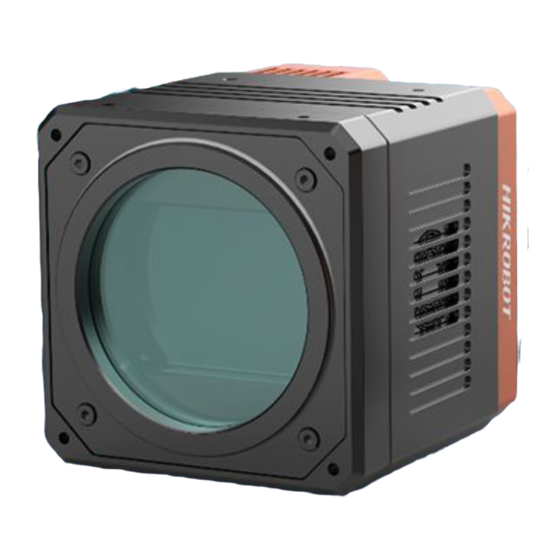
CoaXPress Area Scan Camera User Manual · Chapter 2 Appearance TEC stands for Thermo-Electric Cooler that is able to keep the camera's sensor temperature around environment temperature to ensure the normal operation of the camera. For specific appearance and dimension, please refer to the camera's specification for details. - Page 13 CoaXPress Area Scan Camera User Manual · Figure 2-4 Appearance (Type IV) Figure 2-5 Appearance (Type V) Figure 2-6 Appearance (Type VI) Figure 2-7 Appearance (Type VII)
- Page 14 P10 Connector) input/output signal, etc. CoaXPress Interface It refers to the 4 CoaXPress interfaces for transmitting data. ● For type I, II, IV, V and VI cameras, they uses fan to cool. Fan or TEC ● For type III camera, it uses TEC (inside the camera) to cool.
-
Page 15: Chapter 3 Interface And Indicator
· Chapter 3 Interface and Indicator 3.1 Interface Description All CoaXPress area scan cameras have the same 12-pin P10 connector, as shown below. However, the specific pin definitions are different by camera models. Figure 3-1 12-Pin P10 Connector 3.1.1 First Type of Pin Definitions Regarding the type I and type II cameras, read the table below to get their pin definitions. -
Page 16: Second Type Of Pin Definitions
The camera has different types of indicator with varied models, including camera indicator and CoaXPress linking indicator. For type I and type II cameras, they have camera indicator only. For other types of cameras, they both have camera indicator and CoaXPress linking indicator. -
Page 17: Coaxpress Linking Indicator Status
3.2.2 CoaXPress Linking Indicator Status The CoaXPress linking indicator is used to display CoaXPress linking connection status via CoaXPress cable. For cameras with CXP-6 interface, refer to the Table 3-4 for the status of CoaXPress linking indicator. When the indicator is flashing rapidly, flashing slowly, or flashing very slowly, its unlit interval is 0.08 s, 1 s, and 2 s respectively. - Page 18 CoaXPress Area Scan Camera User Manual · Status Description This status is not applicable to the camera that supports PoCXP. Solid orange The camera system is starting. Slow flashing orange The camera is acquiring images in trigger mode. Rapid flashing...
-
Page 19: Chapter 4 Installation
Make sure all the related equipment is powered off during the installation. The camera has 4 CoaXPress interfaces, and it can transmit data via 1, 2 or 4 interface(s). If you need to use 1 interface, the corresponding interface number is CXP 1. If 2 interfaces are required, the corresponding interface number is CXP 1 and CXP 2. - Page 20 The specific CXP interface No. may differ by camera models. For example, some cameras may have CXP 0, CXP 1, CXP 2 and CXP 3. It is recommended to install the CoaXPress frame grabber into a free PCIe x 16 slot of the PC. Steps: 1.
-
Page 21: Chapter 5 Camera Connection
This section introduces how to install the client software, connect the camera to the client software, etc. 5.1 Intsall Frame Grabber Software The CoaXPress frame grabber client software is used to view and set camera parameters, and acquire images. Obtain the frame grabber software installation package and driver package from frame grabber supplier, and install the frame grabber software and frame grabber driver accordingly. - Page 22 CoaXPress Area Scan Camera User Manual · Figure 5-1 Installation Interface 4. Click Start Setup. Figure 5-2 Default Settings 5. Keep default settings, and click Next. 6. Finish the installation according to the interface prompts.
-
Page 23: Connect Camera To Mvs Client Software
CoaXPress Area Scan Camera User Manual · 5.3 Connect Camera to MVS Client Software Steps: 1. Double click MVS client software to run it. 2. Click beside GenTL in the device list, and click OK in the popup window. Figure 5-3 Refresh List 3. -
Page 24: Chapter 6 Client Software Layout
CoaXPress Area Scan Camera User Manual · Chapter 6 Client Software Layout After connecting to the camera, the client software can read the camera attributes and display them. Figure 6-1 Main Window For specific main window of the client software, please refer to the actual one you got. - Page 25 You can set the parameters of transport layer of the camera. You can save or load the camera's parameters. You can set the User Set Control default parameter when running the frame grabber client software. CoaXPress You can set CoaXPress related parameters.
-
Page 26: Chapter 7 Camera Features
CoaXPress Area Scan Camera User Manual · Chapter 7 Camera Features 7.1 Global Shutter For camera that supports global shutter, its exposure starts and ends in each line simultaneously. After the exposure, data readout starts line by line. All pixels expose at the same time, then readout at different time. -
Page 27: Sensor Shutter Mode
CoaXPress Area Scan Camera User Manual · 7.3 Sensor Shutter Mode Only some models of cameras with rolling shutter and corresponding firmware support the sensor shutter mode. The actual product you purchased should prevail. Stopping the real-time acquisition is required before setting the sensor shutter mode. -
Page 28: Overlap Exposure
CoaXPress Area Scan Camera User Manual · 7.4 Overlap Exposure Overlap exposure refers to the overlap between the current frame exposure and the previous frame readout. In other words, when the previous frame starts to read out, the current frame starts to expose simultaneously. -
Page 29: Chapter 8 Image Acquisition
CoaXPress Area Scan Camera User Manual · Chapter 8 Image Acquisition 8.1 Set Frame Rate Frame rate refers to the image number that is acquired by the camera per second. The higher frame rate, and shorter time used for image acquisition will be. The following 4 factors determine the camera’s frame rate in real-time. -
Page 30: Set Acquisition Mode
CoaXPress Area Scan Camera User Manual · If the current real-time frame rate is larger than configured frame rate, the camera acquires images according to the configured frame rate. 8.2 Set Acquisition Mode The camera has 2 types of acquisition modes, including SingleFrame mode and Continuous mode. -
Page 31: External Trigger Mode
Principle Source Software Trigger Acquisition Control > Software The software sends trigger signal Trigger Selector > to the camera via CoaXPress Trigger Source interface to acquire images. Hardware Trigger Acquisition Control > Line 0, Line 2 External device connects camera Trigger Selector >... -
Page 32: Set Software Trigger
CoaXPress Area Scan Camera User Manual · Click Trigger Selector > Trigger Source, and select Trigger Source according to actual demands. Figure 8-4 Set External Trigger Source 8.4.2 Set Software Trigger Steps: 1. Click Acquisition Control > Trigger Selector. 2. Select On as Trigger Mode. -
Page 33: Set Counter Trigger
CoaXPress Area Scan Camera User Manual · Steps: 1. Click Digital IO Control. 2. Select Line 2 as Line Selector, and Input as Line Mode to set line 2 as input signal. Figure 8-6 Set Line 2 as Input Signal 3. - Page 34 CoaXPress Area Scan Camera User Manual · Figure 8-8 Set Counter Trigger When using counter trigger, you need to set relevant parameters of Counter And Timer Control. Table 8-2 Description of Counter and Timer Control Parameter Read/Write Description Counter Selector Read and write It selects counter source.
-
Page 35: Set Link Trigger
For different models of camera, the counter trigger function may differ, and the actual device you purchased shall prevail. 8.4.5 Set Link Trigger The camera supports trigger via CoaXPress frame grabber, and you can set related parameters as follows. Steps: 1. -
Page 36: Set Free Trigger
CoaXPress Area Scan Camera User Manual · 8.4.6 Set Free Trigger In the free trigger mode, the camera can receive signals from software trigger, hardware trigger, and link trigger. Free trigger function may differ by camera models. Steps: 1. Click Acquisition Control > Trigger Selector. -
Page 37: Set Burst Frame Count
CoaXPress Area Scan Camera User Manual · Sources Software Hardware Counter Link Trigger Free Trigger Trigger Trigger Trigger Parameters Trigger Activation × √ √ √ √ Trigger Debouncer × √ × × × 8.5.1 Set Burst Frame Count Under external trigger mode, you can set burst frame count. Click Acquisition Control >... -
Page 38: Set Trigger Delay
CoaXPress Area Scan Camera User Manual · 8.5.2 Set Trigger Delay From camera receiving signal and responding, this period is trigger delay. Its sequence diagram is shown below. Figure 8-14 Signal Delay Sequence Diagram Here we take the rising edge as the trigger signal. -
Page 39: Set Trigger Activation
CoaXPress Area Scan Camera User Manual · Figure 8-16 Enable Trigger Cache Enable If the camera receives the 1st trigger signal first, and the camera receives the 2nd trigger signal during processing the 1st trigger signal. Disable Trigger Cache Enable: The 2nd trigger signal will be filtered without processing. -
Page 40: Set Trigger Debouncer
CoaXPress Area Scan Camera User Manual · Trigger Activation Parameter Parameter Value Principle Any Edge Acquisition Control > Any Edge If level signal given by external devices Trigger Activation is in rising or falling edge, the camera receives the trigger signal and starts acquisition. - Page 41 CoaXPress Area Scan Camera User Manual · Figure 8-18 Set Trigger Debouncer...
-
Page 42: Chapter 9 I/O Output
CoaXPress Area Scan Camera User Manual · Chapter 9 I/O Output 9.1 Select Output Signal The camera has 1 opto-isolated output (Line 1), and 1 bi-directional I/O (Line 2) that can be configured as output signal. Here we take Line 2 as an example to introduce how to select output signal. You select Line 1 or Line 2 as line selector according to actual demands. -
Page 43: Enable Strobe Signal
CoaXPress Area Scan Camera User Manual · 9.2.2 Enable Strobe Signal The strobe signal is used to directly output I/O signal to external devices when camera’s event source occurs. Click Digital IO Control, select different output events as Line Source, and enable Strobe Enable. - Page 44 CoaXPress Area Scan Camera User Manual · Name Description Soft Trigger Out It refers to output one I/O edge signal when software trigger acquisition. Hard Trigger Active It refers to output one I/O edge signal when hardware trigger acquisition. Count Active It refers to output one I/O edge signal when counter output is enabled.
- Page 45 CoaXPress Area Scan Camera User Manual · When the Strobe Line Duration value is 0, the strobe duration is equal to the exposure time. When the Strobe Line Duration value is not 0, the strobe duration is equal to Strobe Line Duration value.
- Page 46 CoaXPress Area Scan Camera User Manual · Figure 9-8 Set Strobe Line Pre Delay The sequence diagram of strobe line pre delay is shown below. Trigger_in 3 Trigger_in 2 Trigger_in 1 Trigger Trigger Trigger delay delay delay Duration Strobe Exposure...
-
Page 47: Chapter 10 I/O Electrical Feature And Wiring
CoaXPress Area Scan Camera User Manual · Chapter 10 I/O Electrical Feature and Wiring 10.1 I/O Electrical Feature 10.1.1 Line 0 Opto-isolated Input Circuit The Line 0 opto-isolated input circuit in camera I/O control is shown below. Figure 10-1 Line 0 Internal Circuit The maximum input current of Line 0 is 25 mA. -
Page 48: Line 1 Opto-Isolated Output Circuit
CoaXPress Area Scan Camera User Manual · Table 10-1 Input Electrical Feature Parameter Name Parameter Symbol Value Input Logic Level Low 0 VDC to 1 VDC Input Logic Level High VH 3.3 VDC to 24 VDC Input Rising Delay 1.8 μs to 4.6 μs Input Falling Delay 16.8 μs to 22 μs... -
Page 49: Line 2 Bi-Direction I/O Circuit
CoaXPress Area Scan Camera User Manual · When the external voltage is 3.3 VDC and the external resistance is 1 KΩ, opto-isolated output electric feature is shown in below Table 10-2 Output Electric Feature Parameter Name Parameter Symbol Value Output Logic Level Low... - Page 50 CoaXPress Area Scan Camera User Manual · Figure 10-5 Line 2 Bi-direction I/O Circuit Line 2 Configured as Input With the condition of 100 Ω and 5 VDC, the logic level and electrical feature of configuring Line 2 as output are shown below.
- Page 51 CoaXPress Area Scan Camera User Manual · The breakdown voltage is 30 VDC, and keep voltage stable. To prevent damage to GPIO pin, please connect GND first and then input voltage in Line 2 pin. Line 2 Configured as Output The maximum current is 25 mA and the output impedance is 40 Ω.
-
Page 52: I/O Wiring
CoaXPress Area Scan Camera User Manual · Table 10-6 Electrical Feature of Line 2 Output Parameter Name Parameter Symbol Value Output Rising Time 0.06 μs Output Falling Time 0.016 μs Output Rising Delay 0 μs to 4μs Output Falling Delay <... -
Page 53: Line 1 Wiring
CoaXPress Area Scan Camera User Manual · Camera Power NPN Power ● Opto-isolated Signal Line NPN Device ● Input Opto-isolated NPN Power Signal Ground ● Ground Camera Power Ground GND of VCC GND of PWR Figure 10-9 Line 0 Connecting to NPN Device ... -
Page 54: Line 2 Wiring
CoaXPress Area Scan Camera User Manual · NPN Device If the VCC of NPN device is 24 VDC, and it is recommended to use 4.7 KΩ pull-up resistor. If the VCC of NPN device is 12 VDC, and it is recommended to use 1 KΩ pull-up resistor. - Page 55 CoaXPress Area Scan Camera User Manual · Camera Power NPN Power ● NPN Device Bi-direction I/O Signal Line ● NPN Power Camera Power ● Ground Ground GND of PWR and VCC Figure 10-14 Line 2 Connecting to NPN Device as Input ...
- Page 56 CoaXPress Area Scan Camera User Manual · NPN Device If the VCC of NPN device is 24 VDC, and it is recommended to use 4.7 KΩ pull-up resistor. If the VCC of NPN device is 12 VDC, and it is recommended to use 1 KΩ pull-up resistor.
-
Page 57: Chapter 11 Image Parameter
CoaXPress Area Scan Camera User Manual · Chapter 11 Image Parameter 11.1 View Resolution Click Image Format Control, and view Width Max and Height Max. Width Max stands for the max. pixels per inch in width direction and Height Max stands for the max. pixels per inch in height direction. -
Page 58: Set Image Reverse
CoaXPress Area Scan Camera User Manual · Figure 11-2 Set ROI The Width value plus Offset X value should not be larger than Width Max parameter value, Height value plus Offset Y value should not be larger than Height Max parameter value ... -
Page 59: Set Pixel Format
CoaXPress Area Scan Camera User Manual · Figure 11-3 Set Image Reverse Figure 11-4 Image Reverse Comparison 11.4 Set Pixel Format The pixel format may differ by camera models. The relation among ADC bit depth, pixel format and pixel size is shown below. -
Page 60: Set Test Pattern
CoaXPress Area Scan Camera User Manual · ADC Bit Depth Pixel Format Pixel Size (Bits/Pixel) Mono 8, Bayer 8 Mono 10, Bayer 10 Mono 12, Bayer 12 RGB 8 Mono 8, Bayer 8 Mono 10, Bayer 10 Mono 12, Bayer 12... - Page 61 CoaXPress Area Scan Camera User Manual · Click Image Format Control > Test Pattern Generator Selector > Test Pattern, and set Test Pattern according to actual demands. Figure 11-6 Test Pattern The mono camera offers 4 test patterns, including Mono Bar, Checkboard, Oblique Mono Bar , Gradual Mono Bar, and Test Image 1.
- Page 62 CoaXPress Area Scan Camera User Manual · Figure 11-8 Checkboard Test Pattern Figure 11-9 Oblique Mono Bar Test Pattern Figure 11-10 Gradual Mono Bar Test Pattern...
-
Page 63: Set Binning
CoaXPress Area Scan Camera User Manual · Figure 11-11 Vertical Color Bar Test Pattern Figure 11-12 Horizontal Color Bar Test Pattern Figure 11-13 Test Image 1 The pattern of the test image 1 may differ by camera models. 11.6 Set Binning The purpose of setting binning is to enhance sensibility. -
Page 64: Set Decimation
CoaXPress Area Scan Camera User Manual · Figure 11-14 Set Binning Binning Horizontal refers to the image’s width, and Binning Vertical refers to the image’s height. For different models of camera, the binning function may be different, please refer to the actual one you got. -
Page 65: Set Exposure Time Mode
CoaXPress Area Scan Camera User Manual · Timed: Timed exposure. The exposure duration time is set using the Exposure Time or Exposure Auto features and the exposure starts with the Frame Start. Trigger Width: Uses the width of the current frame signal (s) pulse (e.g., Line 0/2, Link Trigger, etc.) to control the exposure duration. -
Page 66: Set Hdr
CoaXPress Area Scan Camera User Manual · Table 11-2 Exposure Method and Principle Exposure Method Principle The camera exposures according to the value configured by user in Exposure Time (µs). Once The camera adjusts the exposure time automatically according to the image brightness. - Page 67 CoaXPress Area Scan Camera User Manual · 2. Set corresponding HDR Shutter, HDR Gain, and HDR Balance Ratio R/G/B. 3. Set HDR Number if you want multiple HDR groups to participate. Up to 8 HDR groups can be configured. 4. Enable HDR Enable.
-
Page 68: Set Gain
CoaXPress Area Scan Camera User Manual · 11.12 Set Gain The gain function may differ by camera models. The camera has 2 types of gain, including the analog gain and digital gain. The analog gain is applied before the signal from the camera sensor is converted into digital values, while digital gain is applied after the conversion. -
Page 69: Set Digital Gain
CoaXPress Area Scan Camera User Manual · When the analog gain is set as Once or Continuous, the gain should be within the range of Auto Gain Lower Limit and Auto Gain Upper Limit. Figure 11-21 Set Analog Gain under Once or Continuous Mode When increasing the analog gain, the image noise will increase too, which will influence image quality. -
Page 70: Set Brightness
CoaXPress Area Scan Camera User Manual · 11.13 Set Brightness The camera brightness refers to the brightness when the camera adjusts image under Once or Continuous exposure mode, or Once or Continuous gain mode. You should enable Once or Continuous exposure mode, or Once or Continuous gain mode first before setting brightness. -
Page 71: Set White Balance
CoaXPress Area Scan Camera User Manual · For different models of camera, the black level range may be different, please refer to the actual one you got. 11.15 Set White Balance White balance is only available for color cameras. The white balance refers to the camera color adjustment depending on different light sources. -
Page 72: Set Gamma Correction
CoaXPress Area Scan Camera User Manual · 4. Take Green as correction standard, and manually adjust other two channels (R channel and B channel) to let these three channels have same value. Here we take Green as an example. For specific Balance Ratio Selector value, please refer to the actual condition. -
Page 73: Set Sharpness
CoaXPress Area Scan Camera User Manual · Steps: 1. Click Analog Control > Gamma Selector. 2. Select User as Gamma Selector. 3. Enable Gamma Enable to enable it. 4. Enter Gamma according to actual demands, and its range is from 0 to 4. -
Page 74: Set Aoi
CoaXPress Area Scan Camera User Manual · Figure 11-28 Set Sharpness 11.18 Set AOI The AOI function may differ by camera models. AOI 1 is used when the camera is in once or continuous exposure mode, and AOI 2 is used when the camera is in once or continuous white balance mode. -
Page 75: Set Color Transformation Control
CoaXPress Area Scan Camera User Manual · 11.19 Set Color Transformation Control The function of color transformation control is only available for color cameras. Currently, RGB to RGB is available for Color Transformation Selector only. The color transformation control is used to restore color and eliminate the overlap in the color channels. -
Page 76: Set Saturation
CoaXPress Area Scan Camera User Manual · 11.21 Set Saturation Saturation is only available for color cameras. Adjusting the saturation changes the colorfulness of the colors. A higher saturation, for example, makes colors easier to distinguish. Click Color Transformation Control, enable Color Transformation Enable, enable Saturation Enable, and enter Saturation according to actual demands. -
Page 77: Set Shading Correction
CoaXPress Area Scan Camera User Manual · Figure 11-33 Set LUT 11.23 Set Shading Correction The camera supports shading correction function that improves the image uniformity when you acquire a non-uniformity image due to external conditions. The shading correction type includes LSC correction, FFC correction, FPNC correction, user PRNUC correction, and other corrections. - Page 78 CoaXPress Area Scan Camera User Manual · Figure 11-34 Auto Image Correction Correcting Image via Setting Parameters Some camera models support correcting image via setting parameters to adjust the image brightness according to different scenarios. Steps: 1. Click Shading Correction, select LSC Correction as Shading Selector.
-
Page 79: Lsc Sequencer
CoaXPress Area Scan Camera User Manual · Figure 11-35 Correcting Image via Setting Parameters The LSC correction can be done only when the camera is in full resolution. If you are only interested in certain details in the image, you can use the ROI function. -
Page 80: Ffc Correction
CoaXPress Area Scan Camera User Manual · 3. Enable LSC Target Enable and set LSC Target. The larger value configured in LSC Target, and brighter the image is. The function of LSC Target Enable and LSC Target is only valid before executing Activate Shading. -
Page 81: User Prnuc Correction
CoaXPress Area Scan Camera User Manual · Steps: 1. Click Shading Correction, and select FFC Correction as Shading Selector. 2. Click Execute in Activate Shading, and enable FFC Enable. Figure 11-37 FFC Correction 11.23.4 User PRNUC Correction The camera currently supports user PRNUC (Photo-response Non-Uniformity Correction) function that eliminates vertical line on the images. - Page 82 CoaXPress Area Scan Camera User Manual · Figure 11-39 Other Corrections...
-
Page 83: Chapter 12 Other Functions
Device User ID Read and write preference. Device Revision Read only It is CoaXPress protocol version. Device Manifest Size Read only It is the quantity of GenlCam XML in the camera. Device Manifest Selector Read and write It is the current ID of GenlCam XML. - Page 84 CoaXPress Area Scan Camera User Manual · Parameter Read/Write Description Board Device Type Read only It is the device type. TEC Enable Read and write Enable it to enable TEC function. It sets the max. temperature of sensor. If actual sensor’s temperature is lower than this parameter, and TEC function is not enabled.
-
Page 85: File Access Control
CoaXPress Area Scan Camera User Manual · Parameter Read/Write Description Click Execute to let red indicator flash several times, and Find Me Read and write find device. Device PJ Number Read only It is the device’s project number. 12.2 File Access Control The file access control function may differ by camera models. -
Page 86: Save And Load User Set
CoaXPress Area Scan Camera User Manual · 3. Select a device feature from the drop-down list. Figure 12-2 File Access Window 4. Click Import or Export to import or export according to actual demands. The camera has different process approaches when you select different device features. - Page 87 CoaXPress Area Scan Camera User Manual · Save Parameters Click User Set Control, select a user set in User Set Selector, and click Execute in User Set Save to save parameters. Figure 12-4 Save User Set Load Parameters Click User Set Control, select a user set in User Set Selector, and click Execute in User Set Load to load parameters to the camera.
-
Page 88: Transport Layer Control
It is the ID of image 1. Image2StreamID Read only It is the ID of image 2. The specific parameters of transport layer control may differ by camera models. 12.5 CoaXPress Parameters You can go to CoaXPress attribute to set CoaXPress related parameters. - Page 89 CoaXPress Area Scan Camera User Manual · Table 12-3 CoaXPress Parameter Description Parameter Read/Write Description Device Connection ID Read only It is the ID of the camera’s major link. Read, and write is available Main Host Connection ID when the camera does not It is the camera’s communication tag.
-
Page 90: Update Firmware
CoaXPress Area Scan Camera User Manual · Figure 12-7 Set Link Configuration The specific link configuration values may differ by camera models. 12.6 Update Firmware The camera supports updating firmware via the MVS client software or the USB interface. The USB interface may differ by camera models. - Page 91 CoaXPress Area Scan Camera User Manual · 2. Click to select update files (.dav files) in the local PC. 3. Click Update to start updating. The camera will reboot after updating. Update Firmware via USB Interface Steps: 1. Power on the camera, and connect the camera to the PC via USB data cable.
-
Page 92: Chapter 13 Faq
CoaXPress Area Scan Camera User Manual · Chapter 13 FAQ 13.1 Why the client software is stuck when listing cameras? Reason ● The camera is not connected correctly. ● The frame grabber is not installed firmly. Solution ● Check the wiring between the camera and the frame grabber. -
Page 93: Why The Client Software Does Not Update Frame Rate Information During Live View
CoaXPress Area Scan Camera User Manual · 13.4 Why the client software does not update frame rate information during live view? Reason When the change value of frame rate in frame grabber client software is smaller than 0.5, the frame rate does not update. -
Page 94: Chapter 14 Revision History
CoaXPress Area Scan Camera User Manual · Chapter 14 Revision History Table 14-1 Revision History Version No. Document No. Date Revision Details Modify Section Set HDR. V2.0.9 UD26060B Nov. 1, 2021 Modify Section LSC Correction. Modify Section Appearance. - Page 95 CoaXPress Area Scan Camera User Manual · Appendix A Camera Parameter Index Table Appendix A-1 Camera Parameter Index Attribute Parameter Section Device Control Device Scan Type Section Device Control Device Vendor Name Device Model Name Manufacturer Info. Device Version Device Firmware Version...
- Page 96 CoaXPress Area Scan Camera User Manual · Device PJ Number Image Format Control Width Max Section View Resolution & Set ROI Height Max Region Selector Width Height Offset X Offset Y Reverse X Section Set Image Reverse Reverse Y ADC Bit Depth...
- Page 97 CoaXPress Area Scan Camera User Manual · Trigger Selector Section External Trigger Mode Trigger Mode Trigger Software Trigger Source Trigger Activation Trigger Delay (µs) Trigger Cache Enable Sensor Shutter Mode Section Sensor Shutter Mode Exposure Mode Section Set Exposure Time Mode & Set...
- Page 98 CoaXPress Area Scan Camera User Manual · Auto Gain Upper Limit Digital Shift Digital Shift Enable Brightness Section Set Brightness Black Level Section Set Black Level Black Level Enable Balance White Auto Section Set White Balance AWB Color Temperature Mode...
- Page 99 CoaXPress Area Scan Camera User Manual · Hue Enable Saturation Saturation Enable LUT Control LUT Selector Section Set LUT LUT Enable LUT Index LUT Value LUT Value (All) LUT Save Shading Correction Shading Selector Section Set Shading Correction Activate Shading...
- Page 100 CoaXPress Area Scan Camera User Manual · Control Trigger Counter Event Source Counter Reset Source Counter Reset Counter Value Counter Current Value File Access Control File Selector File Access Control File Operation Selector File Operation Excute File Open Mode File Operation Status...
- Page 101 CoaXPress Area Scan Camera User Manual · Image2StreamID User Set Control User Set Current Section Save and Load User Set User Set Selector User Set Load User Set Save User Set Default CoaXPress Device Connection ID Section CoaXPress Parameters Main Host Connection ID...
- Page 102 UD26060B...
Need help?
Do you have a question about the CoaXPress and is the answer not in the manual?
Questions and answers