Table of Contents
Advertisement
Advertisement
Table of Contents

Subscribe to Our Youtube Channel
Related Manuals for HikRobot MV-CL021-40GM


Summary of Contents for HikRobot MV-CL021-40GM
- Page 1 GigE Line Scan Camera User Manual...
- Page 2 WITHOUT LIMITATION, MERCHANTABILITY, SATISFACTORY QUALITY, OR FITNESS FOR A PARTICULAR PURPOSE. THE USE OF THE PRODUCT BY YOU IS AT YOUR OWN RISK. IN NO EVENT WILL HIKROBOT BE LIABLE TO YOU FOR ANY SPECIAL, CONSEQUENTIAL, INCIDENTAL, OR INDIRECT DAMAGES,...
- Page 3 TO ANY NUCLEAR EXPLOSIVE OR UNSAFE NUCLEAR FUEL-CYCLE, OR IN SUPPORT OF HUMAN RIGHTS ABUSES. THE PERFORMANCE DATA IN THIS PUBLICATION IS BASED ON HIKROBOT'S INTERNAL RESEARCH/EVALUATION. ACTUAL DATA MAY VARY DEPENDING ON SPECIFIC CONFIGURATIONS AND OPERATING CONDITIONS AND HIKROBOT SHALL NOT BEAR THE CONSEQUENCES ARISING THEREFROM.
- Page 4 GigE Line Scan Camera User Manual · dispose of it at designated collection points. For more information see: www.recyclethis.info 2006/66/EC (battery directive): This product contains a battery that cannot be disposed of as unsorted municipal waste in the European Union. See the product documentation for specific battery information.
- Page 5 GigE Line Scan Camera User Manual · under electrification. Avoid contact with exposed circuit. When the device is powered on, avoid contact with exposed junctions and parts. Use the power adapter provided by the regular manufacturer. Do not connect multiple devices to one power adapter, to avoid over-heating or fire hazards caused by overload.
- Page 6 The basic knowledge and operation skills of low voltage wiring and low voltage electronic circuit connection. The ability to comprehend the contents of this manual. Contact Information Hangzhou Hikrobot Technology Co., Ltd. No. 399 Danfeng Road, Binjiang District, Hangzhou, 310051, China E-mail: tech_support@hikrobotics.com Website: https://en.hikrobotics.com/...
-
Page 7: Table Of Contents
GigE Line Scan Camera User Manual · Table of Contents Chapter 1 Overview ........................1 1.1 Introduction ........................1 1.2 Key Feature ......................... 1 Chapter 2 Appearance ........................ 2 Chapter 3 Interface and Indicator ....................4 3.1 Power and I/O Interface ..................... 4 3.1.1 First Type of Pin Definitions .................. - Page 8 GigE Line Scan Camera User Manual · 7.6.1 Acquisition Burst Frame Count ................31 7.6.2 Trigger Activation ....................32 7.6.3 Trigger Delay......................34 7.6.4 Frame/Line Trigger Cache ..................35 7.6.5 Trigger Debouncer ....................37 Chapter 8 I/O Output ....................... 39 8.1 Select Output Signal ......................
- Page 9 GigE Line Scan Camera User Manual · 10.13 Set White Balance ......................68 10.14 Set Gamma Correction ....................69 10.15 Set AOI .......................... 71 10.16 Set Color Transformation Control ................72 10.17 Set Hue ......................... 73 10.18 Set Saturation ....................... 74 10.19 Set Color Adjustment ....................
-
Page 10: Chapter 1 Overview
GigE Line Scan Camera User Manual · Chapter 1 Overview 1.1 Introduction The GigE line scan camera uses the GigE interface to transmit images in real time, and it acquires images and sets parameters via the client software or SDK. The camera is applicable to the printing, textiles, railway, logistics, metallurgy, food, pharmaceutical manufacturing, material sorting, etc. -
Page 11: Chapter 2 Appearance
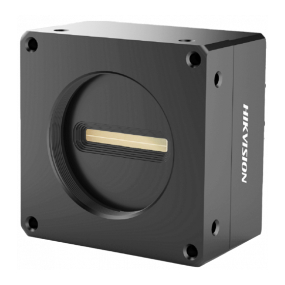
GigE Line Scan Camera User Manual · Chapter 2 Appearance Appearances here are for reference only. Refer to the camera's specification for detailed dimension information and corresponding models. Figure 2-1 Appearance (Type I) Figure 2-2 Appearance (Type II) Figure 2-3 Appearance (Type III) - Page 12 It provides power supply, input/output signal, serial port, etc. Refer to the table below for the relation between camera model and camera appearance type. Table 2-2 Camera Model and Appearance Type Camera Model Camera Appearance Type MV-CL021-40GM Type I camera MV-CL022-40GC MV-CL042-90GM/GC MV-CL022-91GM/GC...
-
Page 13: Chapter 3 Interface And Indicator
But the specific pin definitions differ by camera models. Currently, two pin definitions are available: The first type of pin definitions is applicable to MV-CL021-40GM, MV-CL022-40GC, and MV-CL042-90GM/GC. The second type of pin definitions is applicable to other camera models. -
Page 14: Second Type Of Pin Definitions
GigE Line Scan Camera User Manual · Signal I/O Signal Source Description Line 2- Power supply ground IO_IN1_P Line 3+ Differential input IO 1+ IO_IN1_N Line 3- Differential input IO 1- Line 2+ Bi-directional IO IO_OUT0_P Line 1+ Differential output IO 0+ IO_OUT0_N Line 1- Differential output IO 0-... -
Page 15: Indicator
GigE Line Scan Camera User Manual · Signal I/O Signal Source Description LINE1_P Line 1+ Differential input/output IO 1+ LINE1_N Line 1- Differential input/output IO 1- DC_PWR DC power supply positive LINE4_N Line 4- Differential input/output IO 4- 3.2 Indicator The camera indicator is used to display camera status. -
Page 16: Chapter 4 Camera Installation
GigE Line Scan Camera User Manual · Chapter 4 Camera Installation 4.1 Installation Preparation You need to prepare following accessories before installation. Table 4-1 Accessories Name Quantity Description Lens You should purchase lens separately according to the camera’s lens mount. Lens Adapter You should purchase lens adapter separately according to the camera’s lens mount and lens you use. -
Page 17: Chapter 5 Camera Connection
GigE Line Scan Camera User Manual · Chapter 5 Camera Connection Camera connection to the client software is required for the camera’s configuration and remote operations. This section introduces how to install the client software, set PC and camera network, connect the camera to the client software, etc. -
Page 18: Turn Off Firewall
GigE Line Scan Camera User Manual · Figure 5-2 Default Settings 5. Keep default settings, and click Next. 6. Finish the installation according to the interface prompts. 5.2 Turn off Firewall To ensure stable client running and image transmission, you are recommended turning off Windows firewall before using the client software. -
Page 19: Set Pc Network
GigE Line Scan Camera User Manual · 5.3 Set PC Network To ensure stable image transmission and normal communication between the PC and the camera via client software, you need to set the PC network before using the client software. For different Windows versions, the path name or interface may differ. -
Page 20: Set Camera Network
GigE Line Scan Camera User Manual · Figure 5-5 NIC Configurator The max. value of receive buffers and transmit buffers may differ by network interface cards. 5.4 Set Camera Network You can set and operate the camera in the client software only when the camera is in the same network segment with the PC where the client software is installed. -
Page 21: Connect Camera To Client Software
GigE Line Scan Camera User Manual · Figure 5-6 Modify Device IP Address 5.5 Connect Camera to Client Software Make sure your device IP address is in the same network segment with the PC where you installed the client software before connecting the device to it. Double click the device name in device list, or click to connect the device to the client. -
Page 22: Chapter 6 Client Software Layout
GigE Line Scan Camera User Manual · Chapter 6 Client Software Layout After connecting to the camera, the client software can read the camera attributes and display them. Figure 6-1 Main Window For specific main window of the client software, please refer to the actual one you got. Table 6-1 Description of Main Window Area Name Description... - Page 23 GigE Line Scan Camera User Manual · Area Name Description This area displays the acquisition images in real-time. You can click Display Window different icons to capture and save image, record, etc. You can view and set features of the selected camera, and perform Feature Panel operations such as importing, exporting, and saving features.
- Page 24 GigE Line Scan Camera User Manual · Attribute Description Action Control You can view and set the device’s action control related parameters. Counter And Timer You can view and set the counter related parameters. Control File Access Control You can view and set the device file access control related parameters. You can view and set the device’s event control related parameters to let Event Control the device generate an event and transmit a related event message to...
-
Page 25: Chapter 7 Image Acquisition
GigE Line Scan Camera User Manual · Chapter 7 Image Acquisition 7.1 Set Line Rate Line rate refers to the image line number that is output by the camera per second. The frame rate of the camera is proportional to the line rate, and is inversely proportional to the height of the image area, that is, Fps=Lps (line rate)/Height (image height). -
Page 26: Set Frame Timeout
GigE Line Scan Camera User Manual · Figure 7-2 View Reference Line Rate For different models of camera, the image compression mode function may differ, and the actual product you purchased shall prevail. After enabling the image compression mode, the camera’ s line rate and frame rate are related with exposure and camera sensor only. -
Page 27: Set Acquisition Mode
GigE Line Scan Camera User Manual · Partial Frame Discard Abandon Extra Image Description Enabled Disabled The camera discards the entire image data. Enabled Enabled The camera discards the entire image data. Follow steps below to enable the frame timeout function. Steps: 1. -
Page 28: Set Trigger Mode
GigE Line Scan Camera User Manual · Figure 7-4 Set Acquisition Mode 7.4 Set Trigger Mode The camera has 4 types of trigger modes, including internal trigger mode, line trigger mode, frame trigger mode, and line + frame trigger mode. Table 7-2 Trigger Mode Principle and Parameter Trigger Mode Parameter Parameter Value... -
Page 29: Set Trigger Source
GigE Line Scan Camera User Manual · Trigger Mode Parameter Parameter Value Principle Trigger Selector =Line Start camera specification. Trigger Mode = Off In this mode, the camera's external Trigger Selector =Line Start frame trigger signal and line trigger signal is required. The line number of a Trigger Mode =On Acquisition frame is controlled by the frame height... -
Page 30: Set Software Trigger
GigE Line Scan Camera User Manual · Parameter Trigger Source Parameter Principle Value This trigger source uses shaft encoder module to receive signal A and signal B with phase Shaft encoder Acquisition Control > Encoder difference. After internal computing of the control Trigger Source Module Out... -
Page 31: Set Hardware Trigger
GigE Line Scan Camera User Manual · 3. Select Software as Trigger Source, and click Execute in Trigger Software to send trigger commands. Figure 7-5 Set Software Trigger 7.5.2 Set Hardware Trigger If the camera enables the frame trigger or line trigger, you can select specific lines as trigger source to enable hardware trigger. -
Page 32: Set Shaft Encoder Control
GigE Line Scan Camera User Manual · When selecting bi-directional configurable line as the hardware trigger source, you need to make sure that its line mode is input. Go to Digital IO Control, select specific line as Line Selector, and Input as Line Mode. - Page 33 The 2K camera outputs one signal in one source signal, and the 4K and 8K cameras output four signal in one source signal. 3. (Optional) Regarding MV-CL021-40GM and MV-CL022-40GC cameras, you can set Encoder Trigger Frequency to let the camera output multiple signals, including 1 Tick, 2 Tick and 4...
- Page 34 GigE Line Scan Camera User Manual · Figure 7-9 Process Logic of 1 Tick Figure 7-10 Process Logic of 2 Ticks Figure 7-11 Process Logic of 4 Ticks For other camera models, Encoder Trigger Frequency outputs 4 signals by default. 4.
-
Page 35: Set Frequency Converter Control
GigE Line Scan Camera User Manual · Figure 7-12 Counter Description 5. (Optional) Set max. counter value (0 to 32767) in Encoder Counter Max. Figure 7-13 Set Encoder Counter Max After reaching the max. value, it will be cleared automatically or you can clear manually by clicking Encoder Counter Reset. -
Page 36: View Trigger Line Rate
GigE Line Scan Camera User Manual · Multiplier After the signal is processed by the PreDivider, it is sent to the Multiplier. The Multiplier multiplies the signal by an integer to increase its signal frequency, and then the signal is sent to the PostDivider. -
Page 37: Set Action Command Trigger
GigE Line Scan Camera User Manual · Resulting Trigger Line Rate: It refers to the external trigger frequency cameras received after the external trigger raw line rate is calculated via frequency converter control. It only involves external trigger signals. You need to select external trigger sources as Input Source to display specific values in Trigger Line Rate and Resulting Trigger Line Rate. - Page 38 GigE Line Scan Camera User Manual · Steps: 1. Click Tool > GigE Vision Action Command. 2. Select Network Interfaces to set the subnet that the command to be sent to. 3. Enter the Device Key, Group Key, and Group Mask. Figure 7-16 Set Action Command The specific contents entered in Device Key and Group Key should be the same with those in Action Device Key and Action Group Key of the Action Control feature.
-
Page 39: Set Free Trigger
GigE Line Scan Camera User Manual · 7. (Optional) Enable Periodically Send to enable the client to send commands periodically, and enter Sending Interval according to actual demands. The default value of sending interval is 1000 ms, and its range is from 1 ms to 3600000 ms. 8. -
Page 40: Acquisition Burst Frame Count
GigE Line Scan Camera User Manual · If the frame trigger is enabled, the relation between trigger source and trigger related parameters is shown below. Table 7-4 Trigger Source and Trigger Related Parameters Trigger Source Free Trigger Frequency Software Trigger Hardware Trigger Converter Control Parameters... -
Page 41: Trigger Activation
GigE Line Scan Camera User Manual · Figure 7-18 Set Burst Frame Count When Acquisition Burst Frame Count is 1, it is in single frame trigger mode. When Acquisition Burst Frame Count is larger than 1, it is in multi-frame trigger mode. If Acquisition Burst Frame Count is n and when inputting 1 trigger signal, the camera stops acquiring images after exposing n times and outputs n frame images. - Page 42 GigE Line Scan Camera User Manual · Trigger Activation Parameter Parameter Value Principle Falling Edge Acquisition Control > Falling Edge The camera receives signal and Trigger Activation triggers when the level signal sent by the external device is in the falling edge.
-
Page 43: Trigger Delay
GigE Line Scan Camera User Manual · Figure 7-21 Level Trigger in Frame Trigger Set Trigger Activation in Line Trigger In the line trigger mode, the trigger activation is related with Exposure Mode. When Timed is selected as Exposure Mode, you can select Rising Edge or Falling Edge as Trigger Activation, and Exposure Auto and Exposure Time determine the exposure time. -
Page 44: Frame/Line Trigger Cache
GigE Line Scan Camera User Manual · Figure 7-23 Signal Delay Sequence Diagram You can click Acquisition Control > Trigger Delay, and enter Trigger Delay. Figure 7-24 Set Trigger Delay The sequence diagram above uses rising edge as trigger activation. 7.6.4 Frame/Line Trigger Cache The frame/line trigger cache function may differ by camera models. - Page 45 GigE Line Scan Camera User Manual · Figure 7-25 Set Trigger Cache in Frame Trigger If the camera receives the 1st trigger signal first, and the camera receives the 2nd trigger signal during processing the 1st trigger signal. Disable Trigger Cache Enable: the 2nd trigger signal will be filtered without processing. Figure 7-26 Second Frame Filtered ...
-
Page 46: Trigger Debouncer
GigE Line Scan Camera User Manual · Thus making sure this exposure time is not earlier than the camera’s last frame creation time of the 1st trigger signal. Figure 7-28 Sequence Diagram The three sequence diagrams above use rising edge as trigger activation, and the camera’s height parameter is 4. - Page 47 GigE Line Scan Camera User Manual · Figure 7-30 Trigger Debouncer Sequence Diagram Click Digital IO Control > Line Debouncer Time, and set Line Debouncer Time according to actual demands. Figure 7-31 Set Line Debouncer Time When the configured debouncer time is larger than trigger signal time, and the trigger signal will be ignored.
-
Page 48: Chapter 8 I/O Output
GigE Line Scan Camera User Manual · Chapter 8 I/O Output 8.1 Select Output Signal The selectable output signal line may differ by camera models. The camera has multiple differential output lines or bi-directional configurable lines. The method of setting bi-directional configurable line as output line as follows: Steps: 1. -
Page 49: Enable Line Inverter
GigE Line Scan Camera User Manual · 8.2.1 Enable Line Inverter Go to Digital IO Control, and enable Line Inverter. Figure 8-2 Enable Level Inverter The Line Inverter parameter is disabled by default. 8.2.2 Enable Strobe Signal The strobe signal is used to directly output signal to external devices when the camera’s event source occurs. - Page 50 GigE Line Scan Camera User Manual · If you need to let the camera output signals when event sources occur that are corresponding to each line image, follow steps below to set it. Steps: 1. Click Digital IO Control, and select Line Mode as Strobe Source Selector. 2.
- Page 51 GigE Line Scan Camera User Manual · No. Name Description Frame Burst End Active The camera outputs signals to external devices when frame burst stops. Soft Trigger Active The camera outputs signals to external devices when software trigger starts. Hard Trigger Active The camera outputs signals to external devices when hardware trigger starts.
- Page 52 GigE Line Scan Camera User Manual · Figure 8-5 Set Strobe Line Duration When the Strobe Line Duration value is 0, the strobe duration is equal to the exposure time. When the Strobe Line Duration value is not 0, the strobe duration is equal to Strobe Line Duration value. ...
- Page 53 GigE Line Scan Camera User Manual · The camera’s height parameter is 4 in the sequence diagram above. Set Strobe Line Pre Delay The camera also supports the function of strobe line pre delay, which means that the strobe signal takes effect early than exposure.
-
Page 54: Chapter 9 I/O Electrical Feature And Wiring
· Chapter 9 I/O Electrical Feature and Wiring 9.1 I/O Introduction The I/O signals of MV-CL021-40GM, MV-CL022-40GC, and MV-CL042-90GM/GC cameras are two differential input signals (Line 0/3), two differential output signals (Line 1/4), and one bi-directional configurable signal (Line 2). -
Page 55: Differential Output Circuit
GigE Line Scan Camera User Manual · the receiver and the bus should be as short as possible. The bus must have a 120 Ω terminal resistance. When the camera is the last receiver on the bus structure, the camera's terminal resistance needs to be enabled, and the rest camera's terminal resistance need to be disabled. -
Page 56: Bi-Direction I/O Circuit
GigE Line Scan Camera User Manual · RS-644 Standard Output The camera adopting RS-422 standard output signal cannot directly connect to RS-644 standard. When connecting RS-644 standard output, it is required to add a resistance network in camera’s output location. In order to make sure the normal operation of output circuit, it is required to connect camera’s ground signal with external ground signal. - Page 57 GigE Line Scan Camera User Manual · Make sure the input voltage is not from 1 VDC to 1.5 VDC. The circuit status between the two values is not stable. The breakdown voltage is 30 VDC, and keep voltage stable. ...
-
Page 58: Input Wiring
GigE Line Scan Camera User Manual · Internal Logic Logic 1 Output Level Logic 0 Output Level Figure 9-5 Output Logic Level Table 9-4 Output Electrical Feature Parameter Symbol Value Output Rising Time 0.06 μs Output Falling Time 0.016 μs Output Rising Delay 0 μs to 4μs Output Falling Delay... - Page 59 GigE Line Scan Camera User Manual · The voltage of the differential signal source is 5 V. Camera Power Signal Source Power Differential Differential Input Positive Signal OUT A Source Differential Input Negative OUT Ã Signal Source Power Ground Camera Power Ground Camera GND Signal Source GND Figure 9-6 5 V Differential Signal Source Outputs Differential Signal The voltage of the differential signal source is 12 V or 24 V.
- Page 60 GigE Line Scan Camera User Manual · Signal Source Power Camera Power Differential Input Positive Differential OUT A Signal Source Hang Differential Input Negative Signal Ground Signal Source Power Ground Camera Power Ground Camera GND Signal Source GND Figure 9-8 Differential Signal Source Outputs Single-Ended Signal When the PNP single-ended signal source provides signal, and the camera’s differential input is used as single-ended input.
-
Page 61: Seond Type Of Input Wiring
GigE Line Scan Camera User Manual · When the NPN single-ended signal source provides signal, and the camera’s differential input is used as single-ended input. The VCC of NPN single-ended signal source is 5 V, 12 V or 24 V. Camera Power Signal Source Power 1 kΩ... - Page 62 GigE Line Scan Camera User Manual · Signal Source Power Camera Power LINE*P OUT A Differential Signal LINE*N OUT Ã Source Signal Source Power Ground Camera Power Ground Figure 9-13 Differential Input Wiring When the PNP single-ended signal source provides signal, there are two different wirings as shown below.
-
Page 63: Output Wiring
GigE Line Scan Camera User Manual · When the NPN single-ended signal source provides signal, the wiring is shown below. Signal Source Power Camera Power R (1 KΩ to 10 KΩ) LINE*P Signal Line NPN Single- Ended Signal LINE*N Hang Source Signal Source Power Ground Camera Power Ground... - Page 64 GigE Line Scan Camera User Manual · If the triggered device needs a LVTTL of 3.3 V and below, the wiring is shown below. Camera Power LINE*P Signal Line Triggered Device LINE*N Hang Power Ground of Trigger Device Camera Power Ground Figure 9-18 Single-Ended Output Wiring without Pull-Up Resistor ...
-
Page 65: Chapter 10 Image Parameter
GigE Line Scan Camera User Manual · Chapter 10 Image Parameter 10.1 Image Resolution Click Image Format Control, and check Width Max and Height Max. Width Max stands for the max. pixels per inch in width direction and Height Max stands for the max. pixels per inch in height direction. -
Page 66: Set Image Reverse
GigE Line Scan Camera User Manual · Figure 10-2 Set ROI The Width value plus Offset X value should not be larger than Width Max parameter value. For different models of camera, the above-mentioned setting steps will be different, please refer to the actual one you got. -
Page 67: Set Image Compression Mode
GigE Line Scan Camera User Manual · 10.4 Set Image Compression Mode The function of the image compression is related with camera models, firmware and pixel format, and the actual product you purchased should prevail. Without affecting image quality, the High Bandwidth (HB) function allows the camera to speed up line and frame rates beyond the nominal link capacity. - Page 68 GigE Line Scan Camera User Manual · Figure 10-6 Bayer GR Pixel Pattern Figure 10-7 Bayer GB Pixel Pattern Figure 10-8 Bayer BG Pixel Pattern Figure 10-9 Bayer RG Pixel Pattern Figure 10-10 Bayer RBGG Pixel Pattern For different pixel formats, they have varied data formats, and their relation is shown below. For max.
-
Page 69: Set Test Pattern
GigE Line Scan Camera User Manual · Pixel Format Pixel Size(Bits/Pixel) Mono10 Packed, Mono 12 Packed, Bayer 10 Packed, Bayer 12 Packed Mono 10/12, Bayer 10/12, YUV422Packed, YUV 422 (YUYV) Packed RGB 8, BGR 8 Click Image Format Control > Pixel Format, and set Pixel Format according to actual demands. Figure 10-11 Set Pixel Format 10.6 Set Test Pattern The test pattern may differ by camera models. - Page 70 GigE Line Scan Camera User Manual · Figure 10-12 Test Pattern of Color Camera The mono camera offers 4 test patterns, including Mono Bar, Checkboard, Oblique Mono Bar Gradual Mono Bar, and Test Image 1. For color camera, it also supports Vertical Color Bar and Horizontal Color Bar.
-
Page 71: Set Binning
GigE Line Scan Camera User Manual · Figure 10-16 Gradual Mono Bar Test Pattern Figure 10-17 Vertical Color Bar Test Pattern Figure 10-18 Horizontal Color Bar Test Pattern Figure 10-19 Test Image 1 Test Pattern The pattern of the test image 1 may differ by camera models. 10.7 Set Binning The binning function may differ by camera models. -
Page 72: Set Exposure Auto
GigE Line Scan Camera User Manual · Click Image Format Control, and set Binning Horizontal and Binning Vertical. Figure 10-20 Set Binning Binning Horizontal refers to the image’s width, and Binning Vertical refers to the image’s height. If the camera’s vertical resolution is 1, and there will be Binning Horizontal only. 10.8 Set Exposure Auto The camera supports 3 types of exposure modes: Off, Once and Continuous. -
Page 73: Set Hdr
GigE Line Scan Camera User Manual · Figure 10-21 Set Exposure Time under Once or Continuous Mode If the camera is under Continuous exposure method, once external trigger mode is enabled, the camera will automatically switch to Off exposure mode. 10.9 Set HDR ... -
Page 74: Set Analog Gain
GigE Line Scan Camera User Manual · The camera has 2 types of gain, including the analog gain and digital gain. The analog gain is applied before the signal from the camera sensor is converted into digital values, while digital gain is applied after the conversion. -
Page 75: Set Digital Gain
GigE Line Scan Camera User Manual · If the current gain settings cannot meet demands and images are dark, you can enable ADC Gain x 4 Enable to allow you to set a larger gain, and it adds additional 12 dB to the value you set. Figure 10-24 Set ADC Gain x 4 Enable ... -
Page 76: Set Brightness
GigE Line Scan Camera User Manual · When increasing the digital gain, the image noise will greatly increase too, which will severely influence image quality. It is recommended to use analog gain first, and then to adjust digital gain if the analog gain cannot meet demands. -
Page 77: Set White Balance
GigE Line Scan Camera User Manual · Figure 10-28 Set Black Level 10.13 Set White Balance White balance is only available for color cameras. The white balance refers to the camera color adjustment depending on different light sources. Adjust the Gain Value of the image’s R channel and B channel to keep white regions white under different color temperatures. -
Page 78: Set Gamma Correction
GigE Line Scan Camera User Manual · Figure 10-29 Set AWB Color Temperature Mode If there is still great difference between correction effect and actual color, it is recommended to correct white balance according to following steps. Steps: 1. Select Off as Balance White Auto. At this time, Balance Ratio is 1024. 2. - Page 79 GigE Line Scan Camera User Manual · Gamma=0.5 Gamma=1 Gamma=2 Gamma=4 Figure 10-30 Gamma Curve There are 2 types of Gamma correction, including User mode and sRGB mode. You can set User mode as shown below. Steps: 1. Click Analog Control > Gamma Selector. 2.
-
Page 80: Set Aoi
GigE Line Scan Camera User Manual · Figure 10-32 Set sRGB Mode 10.15 Set AOI The AOI function may differ by camera models. The camera supports AOI function that can adjust the brightness and white balance of the entire image based on the area you selected. Steps: 1. -
Page 81: Set Color Transformation Control
GigE Line Scan Camera User Manual · 10.16 Set Color Transformation Control Color transformation control is only available for color cameras. Under Bayer pixel format, the MV-CL022-40GC camera does not support color transformation control function. After the process of the white balance, the color camera’s overall images will look darker, and multiple colors may deviate from their standard values to some extent. -
Page 82: Set Hue
GigE Line Scan Camera User Manual · Figure 10-35 Method 2 10.17 Set Hue Hue is only available for color cameras. Make sure the camera’s pixel format is not in Mono format. Only the pixel format is YUV, RGB or BGR, the MV-CL022-40GC camera supports hue function. Adjusting the hue shifts the colors of the image. -
Page 83: Set Saturation
GigE Line Scan Camera User Manual · Figure 10-36 Set Hue 10.18 Set Saturation Saturation is only available for color cameras. Make sure the camera’s pixel format is not in Mono format. Only the pixel format is YUV, RGB or BGR, the MV-CL022-40GC camera supports saturation function. -
Page 84: Set Color Adjustment
GigE Line Scan Camera User Manual · Figure 10-37 Set Saturation 10.19 Set Color Adjustment This function may differ by camera models. Color adjustment function allows you to select different color areas in the image to set customized hue and saturation value. Steps: 1. -
Page 85: Set Lut
GigE Line Scan Camera User Manual · Figure 10-39 Set Color Adjustment 10.20 Set LUT A Look-Up Table (LUT) is a customizable grayscale-mapping table. You can stretch, amplify the grayscale range that interests you. The mapping can be linear or customized curve. ... -
Page 86: Set Flat Field Correction
GigE Line Scan Camera User Manual · 10.21 Set Flat Field Correction The fat field correction function and specific setting method may differ by camera models. The fat field correction (FFC) includes PRNUC correction and FPNC correction, and they are used to improve the image uniformity that may be impacted by the sensor, light sources, external conditions, etc. - Page 87 Figure 10-42 Before PRNUC Correction Figure 10-43 After PRNUC Correction Global PRNUC Correction For MV-CL021-40GM camera, follow steps below to operate: Steps: 1. Click Shading Correction, and click Execute in Activate Shading. 2. Enable NUC Enable, and PRNUC Enable will be enabled automatically.
- Page 88 GigE Line Scan Camera User Manual · Select Off as PRNUC Target Enable if you want to use the camera’s auto correction standard. At this time, the camera compares and corrects the average R/G/B component value of each column with the average R/G/B component value of the entire image. ...
-
Page 89: Set Space Correction
GigE Line Scan Camera User Manual · 4. (Optional) Enable PRNUC Smooth Enable to reduce the dust impact during calibration process. Figure 10-46 Set Shading Correction (III) ROI PRNUC Correction If you want to execute PRNUC correction for specific areas, set PRNUC Width and PRNUC Offset X according to actual demands, and enable PRNUC ROI Enable. -
Page 90: Set Line Rate Ratio
GigE Line Scan Camera User Manual · 10.22.1 Set Line Rate Ratio You can go to Shading Correction, and set Line Rate Ratio according to actual demands. Line rate ratio is used to adjust the ratio between the camera’s line rate and that of the actual object to adjust the pixel deviation between upper line and lower line in images. -
Page 91: Set Pixel Shift And Parallax Direction
GigE Line Scan Camera User Manual · Figure 10-48 Set Line Rate Ratio 10.22.2 Set Pixel Shift and Parallax Direction When pixel deviation occurs, images of mono cameras are vague and images of color cameras are dispersive. If you find the image’s edge has pixel deviation via observation, follow steps below to alleviate it. - Page 92 GigE Line Scan Camera User Manual · Camera Type Normal Image Abnormal Image Color Camera Steps: 1. Set Off as Parallax Direction if the image’s edge does not have pixel deviation. 2. Set Parallax Direction according to actual conditions if the image’s edge has pixel deviation. ...
-
Page 93: Chapter 11 Other Functions
GigE Line Scan Camera User Manual · Chapter 11 Other Functions 11.1 Device Control The specific device control parameters may differ by camera models. In the Device Control attribute, you can view device information, edit device name, reset device, etc. The specific parameters in Device Control attribute are shown below. Table 11-1 Device Control Parameter Description Parameter Read/Write... - Page 94 GigE Line Scan Camera User Manual · Parameter Read/Write Description Board Device Type Read only It is the device type. Device Connection Read and It is the ID of GenICam XML. Selector write Device Connection Read only It is the device connection speed. Speed (Mbps) Read and Device Link Selector...
-
Page 95: Embedded Information In Image
GigE Line Scan Camera User Manual · Parameter Read/Write Description Device Character Set Read only It is the character set used in register. Read and Device Reset Click Execute to reset the device. write Device Temperature Read and It selects device component to view temperature. Selector write Sensor supported only. - Page 96 GigE Line Scan Camera User Manual · Table 11-2 Embedded Information Data Format No. Information Type Byte Data Format Description Timestamp 4 Bytes 4 bytes are used to transfer the timestamp information. Gain 4 Bytes 4 bytes are used to transfer the gain information. Each low 8 bits of the 4 valid data are combined to transfer the gain information.
- Page 97 GigE Line Scan Camera User Manual · No. Information Type Byte Data Format Description information comes first. The length and width occupy 2 bytes respectively, and the length information comes first. The specific embedded information categories may differ by camera models. ...
-
Page 98: Tdi Function
GigE Line Scan Camera User Manual · The chunk data function may differ by camera models. The chunk data function is not supported if the camera enables the image compression mode. The camera uses the chunk data function to realize embedded information in image in priority if you enable chunk data function and embedded information function both. -
Page 99: Scan Direction
GigE Line Scan Camera User Manual · TDI refers to Time Delay Integration, and it is a method of line scanning which provides dramatically increased responsivity compared to other video scanning methods. It permits much greater scanning speeds in low light, or allows reduced lighting levels (and costs) at conventional speeds. -
Page 100: File Access Control
GigE Line Scan Camera User Manual · Figure 11-4 Set Scan Direction 11.5 File Access Control The file access function allows you to export or import the camera’s parameters, LUT and user PRNUC, and user FPNC in the mfa format. Currently, the camera supports User Set 1/2/3, LUT Luminance 1/2/3, User PRNUC 1/2/3, and User FPNC. - Page 101 GigE Line Scan Camera User Manual · Figure 11-5 File Access 3. Select Device Feature according to actual demands. Figure 11-6 Select Device Feature 4. Click Import or Export to import or export files. The camera has different process approaches when you select different device features. ...
-
Page 102: Event Control
GigE Line Scan Camera User Manual · 11.6 Event Control The event control function may differ by camera models. The event control function allows you to enable event notification and view camera events. When Event Notification is set as Notification On, the camera can generate an event and transmit a related event message to the computer whenever a specific situation occurs. -
Page 103: Transport Layer Control
GigE Line Scan Camera User Manual · 11.7 Transport Layer Control The specific transport layer control parameters may differ by camera models. You can go to Transport Layer Control to view the camera’s load size, GEV version, etc. Table 11-3 Transport Layer Control Description Parameter Read/Write Description Paylode Size (B) - Page 104 GigE Line Scan Camera User Manual · Parameter Read/Write Description Read and It controls whether incoming pause frames are DEV PAUSE Frame Reception write handled on the given logical link. It is the current IP address for the given network GEV Current IP Address Read only interface.
- Page 105 GigE Line Scan Camera User Manual · Parameter Read/Write Description Read and It indicates the current heartbeat timeout in GEV Heartbeat Timeout (ms) write milliseconds. Read and GEV Heartbeat Disable It disables the GEV Heartbeat. write GEV Timestamp Tick It indicates the number of timestamp ticks in 1 Read only second (frequency in Hz).
- Page 106 GigE Line Scan Camera User Manual · Parameter Read/Write Description GEV Stream Channel Selector Read only It selects the stream channel to control. GEV SCP Interface Index Read only It is the Index of network interface to be used. Read and GEV SCP Host Port It is the host port of the channel write...
-
Page 107: Transfer Control
GigE Line Scan Camera User Manual · 11.8 Transfer Control You can view the camera’s transfer status in transfer control attribute. Figure 11-9 Transfer Control Attribute Table 11-4 Parameter Description Parameter Description Transfer Selector It selects stream channel. Transfer Control Selector It sets control mode, and the camera currently supports Basic only. - Page 108 GigE Line Scan Camera User Manual · Figure 11-10 Parameter Relation You can save parameters, load parameters and set user default as shown below. Here we take selecting User Set 1 as an example. Save Parameters Click User Set Control, select a user set in User Set Selector, and click Execute in User Set Save to save parameters.
-
Page 109: Set Multicast
GigE Line Scan Camera User Manual · Loading parameters is available when connecting with camera, but without acquisition. Set User Default You can also set default parameter by selecting parameter from drop-down list of User Set Default, as shown below. Figure 11-13 Set User Default 11.10 Set Multicast The multicast function may differ by camera models. - Page 110 GigE Line Scan Camera User Manual · For the available camera, you can set multicast function as follows. Steps: 1. Right click the available camera, and click Multicast Settings. Figure 11-14 Click Multicast Settings 2. Select Role, and enter the IP Address and Port. 3.
-
Page 111: Update Firmware
GigE Line Scan Camera User Manual · Figure 11-16 Set Multicast for Connected Camera 11.11 Update Firmware The camera supports updating firmware via the client software. Before updating, make sure power cable and others are properly connected. Please use the firmware package of the corresponding camera model for updating. Steps: 1. - Page 112 GigE Line Scan Camera User Manual · You can only update the firmware when the camera is free, and the camera will reboot automatically after updating the firmware. The firmware updating process may take a few minutes, please wait patiently.
-
Page 113: Chapter 12 Troubleshooting
GigE Line Scan Camera User Manual · Chapter 12 Troubleshooting Table 12-1 Troubleshooting No. Trouble Possible Reason Solution camera found when Camera started Check camera power wiring running client normally, network cable (observe the indicator), and check software. connection error. network connection. -
Page 114: Chapter 13 Revision History
GigE Line Scan Camera User Manual · Chapter 13 Revision History Table 13-1 Revision History Version No. Document No. Date Revision Details Modify section Appearance. V3.4.32 UD24388B Jun. 11, 2021 Modify section Interface and Indicator. Modify section Set Shaft Encoder Control. ... - Page 115 GigE Line Scan Camera User Manual · Modify section Enable Strobe Signal. Add section I/O Introduction. Modify section I/O Electrical Feature. Modify section Input Wiring. Modify section Set Test Pattern. Modify section Set Color Transformation Control.
-
Page 116: Appendix A Camera Parameter Index
GigE Line Scan Camera User Manual · Appendix A Camera Parameter Index Table Appendix A-1 Camera Parameter Index Attribute Parameter Section Device Control Device Type Section Device Control Device Scan Type Device Vendor Name Device Model Name Device Manufacturer Info Device Version Device Firmware Version Device Serial Number... - Page 117 GigE Line Scan Camera User Manual · Device Character Set Device Reset Device Temperature Selector Device Temperature Find Me Device Max Throughput (Kbps) Device PJ Number HB Abnormal Monitor HB Version Image Format Width Max Section Image Resolution Control Height Max Region Selector Section Set ROI Region Destination...
- Page 118 GigE Line Scan Camera User Manual · Information in Image Frame Spec Info TDI Mode Section TDI Function Acquisition Acquisition Mode Section Set Acquisition Mode Control Acquisition Stop Acquisition Burst Frame Count Section Set Line Rate Resulting Line Rate (Fps) Acquisition Line Rate Control Enable Resulting Line Rate (Hz) Reference Line Rate (Hz)
- Page 119 GigE Line Scan Camera User Manual · HDR Selector HDR Shutter Analog Control Preamp Gain Section Set Gain Gain (dB) Gain Auto Auto Gain Lower Limit (dB) Auto Gain Upper Limit (dB) ADC Gain x 4 Enable Digital Shift Digital Shift Enable Brightness Section Set Brightness Black Level...
- Page 120 GigE Line Scan Camera User Manual · Transformation Transformation Control Color Transformation Selector Control Color Transformation Enable Color Transformation Value Selector Color Transformation Value Section Set Hue Hue Enable Saturation Section Set Saturation Saturation Enable Color Adjustment Enable Section Set Color Adjustment Color Adjustment Selector Color Adjustment Hue Color Adjustment Saturation...
- Page 121 GigE Line Scan Camera User Manual · Converter Converter Control Signal Alignment Control Trigger Line Rate (Hz) PreDivider Multiplier PostDivider Resulting Trigger Line Rate (Hz) Shading Section Set Flat Field Shading Selector Correction Correction Activate Shading NUC Enable PRNUC Enable PRNUC ROI Enable PRNUC Width PRNUC Offset X...
- Page 122 GigE Line Scan Camera User Manual · Line Status All Line Debouncer Time (µs) Line Inverter Line Source Strobe Enable Strobe Source Selector Strobe Line Duration Strobe Line Delay Strobe Line Pre Delay Action Control Action Device Key Section Set Action Command Trigger Action Queue Size Action Selector...
- Page 123 GigE Line Scan Camera User Manual · Event Notification Chunk Data Chunk Mode Active Section Embaedded Control Information in Image Chunk Selector Chunl Enable Transport Layer Section Transport Layer Payload Size (B) Control Control GEV Version Major GEV Version Minor GEV Device Mode Is Big Endian GEV Device Mode Character Set GEV Interface Selector...
- Page 124 GigE Line Scan Camera User Manual · GEV Stream Channel Count GEV Heartbeat Timeout (ms) GEV Heartbeat Disable GEV Timestamp Tick Frequency (Hz) Timestamp Control Latch Timestamp Control Reset Timestamp Control Latch Reset Timestamp Value GEV CCP GEV MCP Host Port GEV MCDA GEV MCTT (ms) GEV MCRC...
- Page 125 GigE Line Scan Camera User Manual · Transfer Queue Max Block Count Transfer Queue Current Block Count Transfer Queue Over Flow Count Transfer Queue Mode User Set Section Save and Load User User Set Current Control User Set Selector User Set Load User Set Save User Set Default...
- Page 126 UD24388B...
Need help?
Do you have a question about the MV-CL021-40GM and is the answer not in the manual?
Questions and answers