Table of Contents
Advertisement
Quick Links
Advertisement
Table of Contents

Related Manuals for HikRobot X86


Summary of Contents for HikRobot X86
- Page 1 X86 Open Platform User Manual...
- Page 2 WITHOUT LIMITATION, MERCHANTABILITY, SATISFACTORY QUALITY, OR FITNESS FOR A PARTICULAR PURPOSE. THE USE OF THE PRODUCT BY YOU IS AT YOUR OWN RISK. IN NO EVENT WILL HIKROBOT BE LIABLE TO YOU FOR ANY SPECIAL, CONSEQUENTIAL, INCIDENTAL, OR INDIRECT DAMAGES,...
- Page 3 TO ANY NUCLEAR EXPLOSIVE OR UNSAFE NUCLEAR FUEL-CYCLE, OR IN SUPPORT OF HUMAN RIGHTS ABUSES. THE PERFORMANCE DATA IN THIS PUBLICATION IS BASED ON HIKROBOT’S INTERNAL RESEARCH/EVALUATION. ACTUAL DATA MAY VARY DEPENDING ON SPECIFIC CONFIGURATIONS AND OPERATING CONDITIONS AND HIKROBOT SHALL NOT BEAR THE CONSEQUENCES ARISING THEREFROM.
- Page 4 Indicates a hazard with a high level of risk, which if not avoided, will result in death or serious injury. Available Model This manual is applicable to the X86 Open Platform.
- Page 5 X86 Open Platform User Manual · Safety Instructions These instructions are intended to ensure that the user can use the device correctly to avoid danger or property loss. Laws and Regulations The device should be used in compliance with local laws, electrical safety regulations, and fire prevention regulations.
- Page 6 The basic knowledge and operation skills of low voltage wiring and low voltage electronic circuit connection. The ability to comprehend the contents of this manual. Contact Information Hangzhou Hikrobot Technology Co., Ltd. No. 399 Danfeng Road, Binjiang District, Hangzhou, 310051, China...
- Page 7 X86 Open Platform User Manual · E-mail: tech_support@hikrobotics.com Website: en.hikrobotics.com...
-
Page 8: Table Of Contents
X86 Open Platform User Manual · Table of Contents Chapter 1 Overview ........................1 1.1 Appearance ........................1 1.2 Interface ........................2 1.3 Power and I/O Interface ....................2 1.4 Expansion Interface ....................... 4 1.5 Indicator ........................5 Chapter 2 Device Installation ......................7 2.1 Accessory ........................ - Page 9 9.6.1 Update Firmware via MVS ................... 47 9.6.2 Update Firmware via MvOPCUpgrade ..............48 Chapter 10 Development Guide ....................49 10.1 Enter X86 Open Platform ................... 49 10.2 Operation Process ...................... 49 10.2.1 Adjust Image ..................... 49 10.2.2 Use SDK ......................50 10.2.3 Use Third-Party Software ...................
- Page 10 X86 Open Platform User Manual · 11.1 Overview ........................58 11.2 Interface ........................58 11.3 Indicator ........................60 11.4 I/O Wiring ........................61 11.5 Update Firmware ....................... 62 Chapter 12 Trouble Shooting ......................63 Chapter 13 Revision History ......................64...
-
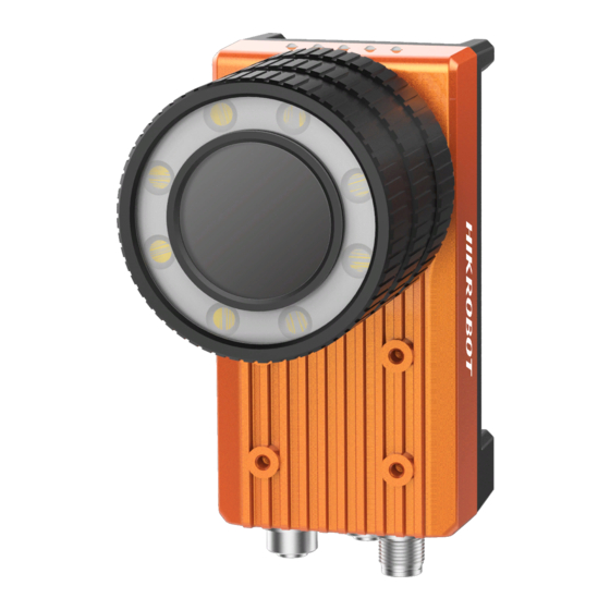
Page 11: Chapter 1 Overview
The dimension of the X86 open platform without light source and lens cover is shown in Figure 1-1. Figure 1-1 X86 Open Platform without Light Source and Lens Cover The dimension of the X86 open platform with light source and lens cover is shown in Figure 1-2. Φ 1 1 3.2... -
Page 12: Interface
X86 Open Platform User Manual · The lens mount of the device is C-mount. 1.2 Interface The device has a RJ45 gigabit Ethernet interface with aviation connector, a 12-pin power and I/O interface, a 17-pin expansion interface. All interfaces are designed with screw threads to tighten connection between the device and cables, and thus avoid influence caused by vibration. - Page 13 X86 Open Platform User Manual · Figure 1-4 Power and I/O Interface Table 1-2 Pin Definitions Signal I/O Type Description Color DC-PWR Power supply DC power + White Power supply Power ground Brown OPTO_OUT0 Output I/O isolated output 0 Green...
-
Page 14: Expansion Interface
X86 Open Platform User Manual · 1.4 Expansion Interface If the device has a 17-pin expansion interface, its interface and the respective pin definitions are shown below. Figure 1-5 Expansion Interface Table 1-3 Pin Definitions Signal Description Color VGA red ground... -
Page 15: Indicator
X86 Open Platform User Manual · Signal Description Color VGA_BLUE_CONN VGA blue Light green USB + USB + Green USB - USB - White VGA_DDCLK_CONN DDC clock Grey VGA _+V5S_CONN VGA power The cable color here refers to the color of cable supplied. If cable of other manufacturers is used, the cable color may differ, and the actual cable you purchased shall prevail. - Page 16 X86 Open Platform User Manual · Table 1-4 Indicator Description Name Indicator Description Power Indicator The indicator is solid blue when the device is powered on. Network Connection The indicator is solid green when the network is Indicator connected. Network Transmission...
-
Page 17: Chapter 2 Device Installation
X86 Open Platform User Manual · Chapter 2 Device Installation 2.1 Accessory You need to prepare following accessories before installation. Table 2-1 Recommended Accessories Name Quantity Description Power and I/O cable × 1 It refers to the 12-pin power and I/O cable. -
Page 18: Install Device
X86 Open Platform User Manual · Instructions on disassembling lamp cup Press the clip in the arrow direction to disassemble the lamp cup Figure 2-1 Install Lens Instructions on disassembling lamp cup Press the clip in the arrow direction to disassemble the lamp cup Figure 2-2 Change Lens 2.3 Install Device... - Page 19 X86 Open Platform User Manual · 安装方式一示意图 Figure 2-3 Installation Method 1 Figure 2-4 Installation Method 2 安装方式三示意图 Figure 2-5 Installation Method 3...
-
Page 20: Wiring
X86 Open Platform User Manual · 2.4 Wiring Follow steps below to wire the device. Steps: 1. Use 8-pin RJ45 network cable with aviation connector to connect the device to a switch or a network interface card (NIC). Figure 2-6 Connect Network Cable 2. - Page 21 X86 Open Platform User Manual · 4. If the expansion interface board is used for power supply, you only need to connect the power cord to corresponding interfaces of the expansion interface board. Figure 2-9 Expansion Interface Board Wiring If device’s built-in light source is not used, you can use 10 VDC to 30 VDC for power supply.
-
Page 22: Chapter 3 Client Installation And Setting
Chapter 3 Client Installation and Setting 3.1 Install MVS Client The MVS client software for X86 open platform is compatible with 32/64-bit Windows XP/7/10 operating systems. Software version in this manual is V3.1.0. If other versions are used, the graphic user interface may differ. - Page 23 X86 Open Platform User Manual · 3. Enable Jumbo Frame. Figure 3-2 Set Jumbo Packet 4. Click Open in the Internet Protocol, select Obtain an IP address automatically, and click OK to save. Figure 3-3 Local NIC Settings 5. Click Apply to take the settings into effect.
-
Page 24: Set Ip Address
X86 Open Platform User Manual · 3.3 Set IP Address Purpose: The online device in the same local subnet with the PC running the software will be displayed in the device list. Before you start: Make sure the device is powered on and connected to the network. -
Page 25: Connect Device To Mvs
X86 Open Platform User Manual · You can modify the IP address of the device if its status is free. When switching between static IP and DHCP, you need to restart the device manually. Change the IP address if the modified IP address conflicts with another device's IP address in the same local subnet. -
Page 26: Chapter 4 Device Setting
X86 Open Platform User Manual · Chapter 4 Device Setting 4.1 Main Window After connecting to the device, the MVS client can read the device attributes and display them in tree format. The main window and its description are shown in Figure 4-1 and Table 4-1 respectively. -
Page 27: Set Parameters
X86 Open Platform User Manual · Area Name Description Device Display the network interface information and the Information Panel device information. Display Window View the real-time image of the device. Feature Panel Display and configure the device’s specific attributes. 4.2 Set Parameters The device setting supports 3 types of user level: Beginner, Expert and Guru, which displays different device attributes. - Page 28 X86 Open Platform User Manual · Table 4-2 Attribute Description Attribute Description You can view device information, edit its name and Device Control reset the device. You can view device’s frame rate, and set exposure, Image Setting gain, brightness, Gamma, etc.
-
Page 29: Chapter 5 Image Acquisition
X86 Open Platform User Manual · Chapter 5 Image Acquisition 5.1 Set Frame Rate You can set frame rate as shown below. Steps: 1. Click Image Setting > Acquisition Frame Rate. 2. Enter frame rate according to actual demands. Figure 5-1 Set Frame Rate The Resulting Frame Rate displays the device’s real-time frame rate. -
Page 30: External Trigger Mode
Principle Source Software trigger Trigger and IO Software The software sends trigger Control > Trigger In signal to the X86 open Source platform to acquire images. Hardware trigger Trigger and IO LineIn 0, LineIn 1, External device connects X86 Control > Trigger In... -
Page 31: Set Software Trigger
X86 Open Platform User Manual · Figure 5-2 Set External Trigger Source These 3 external trigger sources are valid only when the Trigger Mode is On. 5.3.2 Set Software Trigger You can set software trigger as shown below. Steps: 1. Click Trigger and IO Control > Trigger Mode. -
Page 32: Set Counter Trigger
X86 Open Platform User Manual · 2. Select On as Trigger Mode. 3. Select LineIn 0, LineIn 1, or LineIn 2 as Trigger In Source according to actual demands. 5.3.4 Set Counter Trigger The counter trigger provides frequency division to the external trigger signal. You can set counter trigger as shown below. -
Page 33: Set Burst Frame Count
X86 Open Platform User Manual · 5.4.2 Set Burst Frame Count Steps: 1. Click Image Setting > Acquisition Burst Frame Count. 2. Enter proper value according to actual demands, and its range is from 0 to 1023. When Burst Frame Count= 3, 1 trigger signal outputs 3-frame image. The sequence diagram of burst frame count is shown below. -
Page 34: Set Trigger Debouncer
X86 Open Platform User Manual · When triggering via High Level or Low Level, you can also set Start Delay Time(μs) and End Delay Time(μs), as shown below. Figure 5-8 Set Start and End Delay Time 5.4.4 Set Trigger Debouncer The external trigger input signal of the device may have signal bounce that may cause false trigger. - Page 35 X86 Open Platform User Manual · Figure 5-10 Set Trigger Debouncer When the configured deboucer time is longer than the trigger signal time, this trigger signal will be ignored.
-
Page 36: Chapter 6 I/O Output
X86 Open Platform User Manual · Chapter 6 I/O Output 6.1 Set Output Signal The device has 3 output signals, including LineOut 0, LineOut 1, and LineOut 2, which are used to control external devices such as flashing light, etc. You can select output signal as shown below. - Page 37 X86 Open Platform User Manual · For specific Line Out Activation Event, please refer to following table for details. Table 6-1 Output Event Name Description It refers to disable Line Out Activation Event. AcqusitionStartActive It refers to output one I/O edge signal when starting acquisition.
- Page 38 X86 Open Platform User Manual · Figure 6-3 Set Output Delay, Duration or Ahead Time...
-
Page 39: Chapter 7 I/O Wiring
X86 Open Platform User Manual · Chapter 7 I/O Wiring 7.1 I/O Input Wiring I/O interface input wiring method is shown below, and its input voltage ranges from 5 VDC to 30 VDC. Figure 7-1 I/O Input Wiring If the input device is NPN signal (suspended or power negative), IN_COM should be connected with input device power positive, and signal line with corresponding input interface. -
Page 40: I/O Output Wiring
X86 Open Platform User Manual · Power + OPTO IN Signal Line IN _ COM Power Ground Figure 7-3 Connecting to PNP Device 7.2 I/O Output Wiring I/O interface output is open-circuit output, as shown below. Input voltage ranges from 5 VDC to 30 VDC, and current cannot exceed 200 mA. - Page 41 X86 Open Platform User Manual · If the output device is PNP signal (suspended or power positive), the OUT_COM should be connected with input device power negative, and signal line with corresponding input interface. Figure 7-6 Connecting to PNP Device...
-
Page 42: Chapter 8 Image Parameter
X86 Open Platform User Manual · Chapter 8 Image Parameter 8.1 Set Frame Rate You can set frame rate as shown below. Steps: 3. Click Image Setting > Acquisition Frame Rate. 4. Enter frame rate according to actual demands. Figure 8-1 Set Frame Rate The Resulting Frame Rate displays the device’s real-time frame rate. -
Page 43: Set Pixel Format
Figure 8-3 Set Pixel Format 8.4 Set Exposure Mode The X86 open platform supports exposure function. For specific exposure range that the device supports, please refer to the specifications of the device. The device has 3 types of exposure: Off, Once and Continuous. The exposure mode and principle are shown below. - Page 44 X86 Open Platform User Manual · Exposure Parameter Parameter Value Principle Mode Once Image Setting > Once The device adjusts the Exposure Auto exposure time automatically according to the image brightness. After adjustment, it will switch to Off mode. Image Setting >...
-
Page 45: Set Gain
· 8.5 Set Gain The X86 open platform supports gain function. For specific gain range that the device supports, please refer to the specifications of the device. The device has 3 types of gain: Off, Once and Continuous. The gain mode and principle are shown below. -
Page 46: Set Gamma Correction
8.6 Set Gamma Correction The X86 open platform supports Gamma correction function. Generally, the output of the camera’s sensor is linear with the photons that are illuminated on the photosensitive surface of the sensor. -
Page 47: Set Brightness
8.8 Set Image Reverse The X86 open platform supports horizontal reverse image output. Horizontal reverse refers to the image reverses in a horizontal way. You can set image reverse as shown below. Steps: 1. -
Page 48: Set Test Pattern
· 8.9 Set Test Pattern The X86 open platform supports test pattern function. When there is exception in real-time image, you can check whether image of test mode have similar problem to determine the reason. You can set test pattern as shown below. - Page 49 X86 Open Platform User Manual · Figure 8-15 Oblique Mono Bar Test Pattern Figure 8-16 Vertical Stripe Test Pattern Figure 8-17 Transver SeStripe Test Pattern Vertical Stripe and Transver SeStripe are only available for color device.
-
Page 50: Set White Balance
X86 Open Platform User Manual · 8.10 Set White Balance White balance is only available for color device. The white balance refers to the color adjustment depending on different light sources. Adjust the gain value of the image’s R channel and B channel to keep white regions white under different color temperatures. -
Page 51: Set Hue
X86 Open Platform User Manual · 8.11 Set Hue Hue function is only available for color device. You can set hue as shown below. Steps: 1. Click Image Setting > Hue Enable. 2. Enable Hue Enable. 3. Enter proper value in Hue according to actual demand, and its default value is 128. -
Page 52: Multiple Exposure
X86 Open Platform User Manual · 8.13 Multiple Exposure The X86 open platform supports multiple exposure gain mode that can set four groups of exposure time and gain. Steps: 1. Click Image Setting > Multiple Exposure Gain Polling Enable. 2. Enable Multiple Exposure Gain Polling Enable. -
Page 53: Chapter 9 Other Functions
X86 Open Platform User Manual · Chapter 9 Other Functions 9.1 Device Control In the Device Control interface, you can view device information, edit device name, reset device, etc. Steps: 1. Open the client software. 2. Go to Device Control and open the list. -
Page 54: Set Light Source
3. (Optional) Enter proper value in Lighting Duration(µs) and Lighting Ahead Time(µs) to set light source flashing time, and ahead time before exposure respectively. For models of X86 open platform that do not have light source and lens cover do not support this function. -
Page 55: Set Indicator
X86 Open Platform User Manual · Save Parameters Steps: 1. Click User Set Control, and select a user set in User Set Selector. Here we take selecting User Set 1 as an example. 2. Click Execute in User Set Save to save parameters. - Page 56 X86 Open Platform User Manual · Figure 9-6 Set Indicator For specific indicator functions, please refer to following table for details. Table 9-1 Indicator Function Description Name Description It refers to disable this function. Who Am I When selected, click Execute, and indicator flashes once.
-
Page 57: Set Communication Control
X86 Open Platform User Manual · 9.5 Set Communication Control In communication control interface, you can view the number of bytes per image in the transmission stream, and set data packet size. Steps: 1. Click Communication Control > Payload Size(B). -
Page 58: Update Firmware Via Mvopcupgrade
9.6.2 Update Firmware via MvOPCUpgrade The device supports updating firmware via the tool of MvOPCUpgrade. By default, the tool is located in \Program Files(x86)\MVS\ Development\Bin\win32. For different Windows versions, the tool location directory may differ. Please refer to the actual condition. -
Page 59: Chapter 10 Development Guide
Chapter 10 Development Guide 10.1 Enter X86 Open Platform Function development needs to be configured inside the X86 open platform. You can use a VGA or HDMI cable to connect display and external devices, or use a personal computer to operate via remote desktop. -
Page 60: Use Sdk
2. Use the client to connect to the platform, and adjust image according to Section 8 Image Parameter. 10.2.2 Use SDK The X86 open platform SDK contents are integrated with the MVS client. Follow the steps below to view the SDK development material. Steps: 1. - Page 61 If you use third-party software, you need to obtain corresponding dongle. Obtain Stream via Labview Software You can use Labview software to obtain stream for X86 open platform. Steps: 1. Right click MVS icon, and select Open file location.
- Page 62 X86 Open Platform User Manual · 2. Go back 2 levels of directory to find the Development folder. 3. Go to Samples\Labview\Samples, and find Samples.lvproj. Figure 10-5 Find Samples.lvproj 4. Open Samples.lvproj to load MvCameraPatch.dll file, which is located in \MVS\Development\Samples\Labview\ MvLVLib\x86.
- Page 63 X86 Open Platform User Manual · 7. Right click in the flow diagram, select VI and open folder. 8. Go back 1 level of directory to open Vls folder to call sub VI program, as shown below. Figure 10-8 Call VI Program 9.
- Page 64 Obtain Stream via Halcon Software You can use Halcon software to obtain stream for X86 open platform. You can use this software in 2 ways: install the software into your PC to connect the platform, or install the software into X86 open platform.
- Page 65 X86 Open Platform User Manual · 5. Select Connection tab, and click Connect to connect device. If the device is detected, there will be a device name displayed in the right side of Device. Figure 10-13 Connect Device 6. You can click Snap to acquire single frame image, and click Live to acquire images continuously.
- Page 66 X86 Open Platform User Manual · Figure 10-15 Set Image Parameters When installing the software into X86 open platform, you can use Halcon software to obtain stream as follows. Steps: 1. Right click MVS icon, and select Open file location.
- Page 67 X86 Open Platform User Manual · Figure 10-17 Select MVision 6. Connect device, and obtain images.
-
Page 68: Chapter 11 Interface Expansion Module
Chapter 11 Interface Expansion Module 11.1 Overview The X86 open platform is compatible with interface expansion module that is compact, easy to install. The module has 1 VGA interface, 3 USB 2.0 interfaces, 1 RS232 serial port, and 1 RS485 serial port, 1 light source controlling port, and a 7 in/7 out IO port. - Page 69 It refers to VGA display. Power interface It provides power supply. Device interface It connects X86 open platform. Figure 11-3 Back Side of the Interface Expansion Module Table 11-2 Interfaces on the Back Side of the Module Interface Name Description Input interface It inputs I/O signal.
-
Page 70: Indicator
X86 Open Platform User Manual · Interface Name Description RS485 serial port It is the RS485 serial port. RS232 serial port It is the RS232 serial port. 11.3 Indicator The interface expansion module supports real-time IO monitoring, and provides a sufficient number of indicators, as shown below. -
Page 71: I/O Wiring
X86 Open Platform User Manual · Indicator Name Description IN 5 Input signal 5 indicator IN 6 Input signal 6 indicator IN 7 Input signal 7 indicator OUT 1 Output signal 1 indicator OUT 2 Output signal 2 indicator OUT 3... -
Page 72: Update Firmware
X86 Open Platform User Manual · If the input device is NPN signal (suspended or power negative), IN_COM should be connected with input device power positive, and signal line with corresponding input interface. If the input device is PNP signal (suspended or power positive), IN_COM should be connected with input device power negative, and signal line with corresponding input interface. -
Page 73: Chapter 12 Trouble Shooting
X86 Open Platform User Manual · Chapter 12 Trouble Shooting Table 12-1 Trouble Shooting Trouble Possible Reason Solution No device found Device is not started up Check device power wiring (observe when running the normally, or network PWR indicator), and check network client. -
Page 74: Chapter 13 Revision History
X86 Open Platform User Manual · Chapter 13 Revision History Table 13-1 Revision History Version No. Document No. Date Revision Details 2.0.0 UD11162B Jul. 31, 2018 Original version. Adopt MVS version 3.0.0. 2.0.1 UD15058B Jun. 12, 2019 Add Section 8.10 Set White Balance. - Page 75 UD15058B...
Need help?
Do you have a question about the X86 and is the answer not in the manual?
Questions and answers