Table of Contents
Advertisement
Quick Links
Advertisement
Table of Contents

Related Manuals for HikRobot GigE


Summary of Contents for HikRobot GigE
- Page 1 GigE Area Scan Camera User Manual...
- Page 2 The information contained in the Manual is subject to change, without notice, due to firmware updates or other reasons. Please find the latest version of this Manual at the Hikrobot website (https://en.hikrobotics.com/). Please use this Manual with the guidance and assistance of professionals trained in supporting the Product.
- Page 3 ANY NUCLEAR EXPLOSIVE OR UNSAFE NUCLEAR FUEL-CYCLE, OR IN SUPPORT OF HUMAN RIGHTS ABUSES. THE PERFORMANCE DATA IN THIS PUBLICATION IS BASED ON HIKROBOT'S INTERNAL RESEARCH/EVALUATION. ACTUAL DATA MAY VARY DEPENDING ON SPECIFIC CONFIGURATIONS AND OPERATING CONDITIONS AND HIKROBOT SHALL NOT BEAR THE CONSEQUENCES ARISING THEREFROM.
- Page 4 Note important points of the main text. Available Model This manual is applicable to the GigE area scan camera. Safety Instruction These instructions are intended to ensure that the user can use the device correctly to avoid danger or property loss.
- Page 5 GigE Area Scan Camera User Manual instructions. ● The device should be used in an environment that meets the design specifications, otherwise it may cause malfunctions, and malfunctions or component damage caused by non-compliance with relevant regulations are not within the scope of the device's quality assurance.
- Page 6 GigE Area Scan Camera User Manual center. Never attempt to disassemble the device yourself (we shall not assume any responsibility for problems caused by unauthorized repair or maintenance). ● Please dispose of the device in strict accordance with the relevant national or regional regulations and standards to avoid environmental pollution and property damage.
- Page 7 GigE Area Scan Camera User Manual isolation, and consider adding a DC/DC isolation power supply module between the device and the adapter. ● Use the power adapter to supply power to the device separately. If centralized power supply is necessary, make sure to use a DC filter to filter the power supply of the device separately before use.
-
Page 8: Table Of Contents
GigE Area Scan Camera User Manual Contents Chapter 1 Overview ........................... 1 1.1 Introduction ......................... 1 1.2 Key Feature .......................... 1 Chapter 2 Appearance ........................2 Chapter 3 I/O Connector and Indicator..................6 3.1 Power and I/O Connector ....................6 3.2 Indicator .......................... - Page 9 GigE Area Scan Camera User Manual 8.4 Set Trigger Mode ......................24 8.4.1 Enable Internal Trigger Mode ................24 8.4.2 Enable External Trigger Mode ................25 8.5 Set Trigger Source ......................25 8.6 Set Trigger Related Parameters ..................29 Chapter 9 Trigger Output ....................... 35 9.1 Select Output Signal ......................
- Page 10 GigE Area Scan Camera User Manual 11.13.1 Set Sequencer ....................63 11.13.2 Set HDR ......................65 11.14 Set Gain ......................... 66 11.14.1 Set Analog Gain ....................66 11.14.2 Set Digital Gain ....................67 11.15 Set Sensor Mode ......................67 11.16 Set Brightness ......................68 11.17 Set Black Level ......................
- Page 11 13.3 Why the live view is back? ..................106 13.4 Why the device cannot be triggered although the live view is normal? ....107 13.5 Why the network changes from GigE Ethernet to Fast Ethernet? ......107 Appendix A Device Parameter Index ..................108...
-
Page 12: Chapter 1 Overview
Chapter 1 Overview 1.1 Introduction The GigE area scan camera uses the GigE interface to transmit non-compressed images in real time, and it acquires images and sets parameters via the client software or SDK. The GigE area scan camera is applicable to the automated optical inspection (AOI) for the surface mounted technology and the printed circuit board, electronic semiconductor, factory automation, logistics industry, etc. -
Page 13: Chapter 2 Appearance
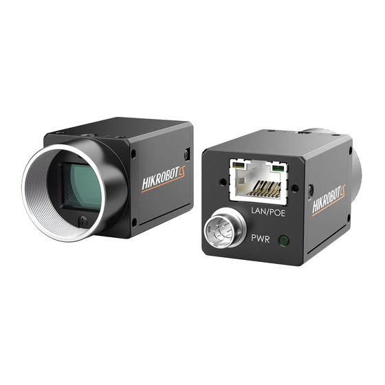
GigE Area Scan Camera User Manual Chapter 2 Appearance Note ● For specific appearance and dimension, please refer to the device’s specification for details. ● The appearance is subject to change, and the actual device you purchased shall prevail. The specific device appearance types are as follows: ●... - Page 14 GigE Area Scan Camera User Manual Figure 2-2 Appearance (Type II) Figure 2-3 Appearance (Type III) Figure 2-3 Appearance (Type IV)
- Page 15 GigE Area Scan Camera User Manual Figure 2-4 Appearance (Type V) Figure 2-5 Appearance (Type VI) Figure 2-6 Appearance (Type VII)
- Page 16 It is used to fix the device to the installation position. Screw Hole Refer to the device’s specification for specific screw information. GigE Interface It refers to the GigE interface for transmitting data. Screw Hole of GigE It refers to the M2 screw hole for fixing the network Interface cable.
-
Page 17: Chapter 3 I/O Connector And Indicator
GigE Area Scan Camera User Manual Chapter 3 I/O Connector and Indicator 3.1 Power and I/O Connector The device has a 6-pin P7 connector or 12-pin P10 connector as the power and I/O connector that provides power supply, input/output signal and serial port function. - Page 18 GigE Area Scan Camera User Manual Signal I/O Signal Source Description Line 0-/1-/2- Device’s power supply ground Line 0-/1-/2- Device’s power supply ground Table 3-2 Pin Definitions of 6-Pin P7 Connector (Other Series) Signal I/O Signal Source Description DC_PWR Device’s power supply...
-
Page 19: Indicator
GigE Area Scan Camera User Manual Signal I/O Signal Source Description Reserved Reserved OPTO_GND Line 0-/1- Opto-isolated signal ground Reserved Reserved RS-232_RX RS-232 receives RS-232_TX RS-232 transmits GPIO Can be configured as input or Line 2+ output OPTO_OUT Line 1+... -
Page 20: Chapter 4 Installation
Steps 1. Fix the device to the installation position. 2. Install the lens to the device. 3. Use a proper network cable to connect device with a GigE switch or a network interface card. 4. Select a power supply method: ●... -
Page 21: Chapter 5 Device Connection
GigE Area Scan Camera User Manual Chapter 5 Device Connection Device connection to the client software is required for device’s configurations and remote operations. This section introduces how to install the client software, connect the device to the client software, etc. -
Page 22: Set Pc Environment
GigE Area Scan Camera User Manual Figure 5-2 Default Settings 5. Keep default settings, and click Next. 6. Finish the installation according to the interface prompts. 5.2 Set PC Environment To ensure stable client running and data transmission, you are recommended to set PC environment. -
Page 23: Set Pc Network
GigE Area Scan Camera User Manual Figure 5-3 Windows Defender Firewall 4. Click OK. 5.2.2 Set PC Network Steps Note For different Windows versions, the specific setting path and interface may differ. Please refer to the actual condition. 1. Go to PC network settings page: Start → Control Panel → Network and Internet →... - Page 24 Interrupt Moderation Rate to Extremum. 4. (Optional) Set NIC property via the MVS. 1) Right click the GigE, and click NIC Settings. Figure 5-5 Click NIC Settings 2) Enable Jumbo Frame, and set Receive Buffers and Transmit Buffers to 2048.
-
Page 25: Set Device Network
GigE Area Scan Camera User Manual 5.3 Set Device Network You can set and operate the device in the client software only when the device is in the same network segment with the PC where the client software is installed. -
Page 26: Chapter 6 Client Software Layout
GigE Area Scan Camera User Manual Chapter 6 Client Software Layout After connecting to the device, the client software can read its attributes and display them. Figure 6-1 Main Window Note For specific main window of the client software, please refer to the actual one you got. - Page 27 GigE Area Scan Camera User Manual Click in the device’s feature panel to unfold the specific parameters, and set them according to actual demands. Note The device’s feature tree and parameters may differ by device models. Table 6-2 Feature Tree Description...
-
Page 28: Chapter 7 Device Feature
GigE Area Scan Camera User Manual Chapter 7 Device Feature 7.1 Global Shutter For device that supports global shutter, its exposure starts and ends in each line simultaneously. After the exposure, data readout starts line by line. All pixels expose at the same time, then readout at different time. -
Page 29: Sensor Shutter Mode
GigE Area Scan Camera User Manual Figure 7-2 Rolling Shutter 7.3 Sensor Shutter Mode Note ● Only some models of devices with rolling shutter and corresponding firmware support the sensor shutter mode. The actual product you purchased should prevail. ● Stopping the real-time acquisition is required before setting the sensor shutter mode. - Page 30 GigE Area Scan Camera User Manual Figure 7-3 Global Reset Rolling means that the device exposes the pixel rows one after the other, and it supports sensor's pixels exposure and pixel data readout proceeding at the same time. While trigger rolling does not support that sensor's pixels exposure and pixel data readout proceed at the same time.
-
Page 31: Non-Overlap Exposure And Overlap Exposure
GigE Area Scan Camera User Manual 7.4 Non-Overlap Exposure and Overlap Exposure The process that the device captures one frame of image includes two stages, exposure and readout. According to the overlap relation between the exposure time and the readout time, devices with different sensors can be divided into overlap exposure and non-overlap exposure. -
Page 32: Overlap Exposure
GigE Area Scan Camera User Manual 7.4.2 Overlap Exposure Overlap exposure refers to the overlap between the current frame exposure and the previous frame readout. In other words, when the previous frame starts to read out, the current frame starts to expose simultaneously, as shown below. -
Page 33: Chapter 8 Image Acquisition
GigE Area Scan Camera User Manual Chapter 8 Image Acquisition 8.1 Set Frame Rate Note The image compression function may differ by device models Frame rate refers to the image number that is acquired by the device per second. The higher frame rate, and shorter time used for image acquisition will be. -
Page 34: Set Overlap Mode
GigE Area Scan Camera User Manual Note ● If the real-time frame rate is smaller than the value you set, the device acquires images by the real-time frame rate. ● If the real-time frame rate is larger than the value you set, the device acquires images by the value you set. -
Page 35: Set Acquisition Mode
GigE Area Scan Camera User Manual 8.3 Set Acquisition Mode The device supports two types of acquisition modes, including SingleFrame mode and Continuous mode. Go to Acquisition Control → Acquisition Mode, and select Continuous or SingleFrame as Acquisition Mode according to actual demands. -
Page 36: Enable External Trigger Mode
Trigger Source according to actual demands. Table 8-1 Trigger Source Description Trigger Source Parameter Description Software The software sends trigger signal to the device via GigE Software Trigger interface to acquire images. External device connects device via device I/O interface. Hardware... - Page 37 Note These five external trigger sources are valid only when the Trigger Mode is On. Set and Execute Software Trigger In software trigger, the software sends trigger signal to the device via GigE interface to acquire images. Steps 1. Go to Acquisition Control → Trigger Mode, and select On as Trigger Mode.
- Page 38 GigE Area Scan Camera User Manual Figure 8-9 Set Line 2 as Input Signal In hardware trigger, external device sends trigger signal to the device to acquire images via I/O connector. Steps 1. Go to Acquisition Control → Trigger Mode, and select On as Trigger Mode.
- Page 39 GigE Area Scan Camera User Manual Parameter Read/Write Description It selects the signal source of counter trigger. Counter Event Source Read and write Line 0 or Line 2 is available. This parameter is disabled by default. Counter Reset Source Read and write It selects the signal source of resetting counter.
-
Page 40: Set Trigger Related Parameters
GigE Area Scan Camera User Manual Figure 8-13 Set and Execute Action Command Trigger Note For specific function of action commands, please refer to the section Set Action Command for details. Set and Execute Free Trigger In free trigger, the device can receive software trigger and hardware trigger to acquire images. - Page 41 GigE Area Scan Camera User Manual Set Acquisition Burst Frame Count In external trigger mode, you can set acquisition burst frame count. Go to Acquisition Control → Acquisition Burst Frame Count, and enter Acquisition Burst Frame Count according to actual demands.
- Page 42 GigE Area Scan Camera User Manual level low, the device is in image acquisition status. Figure 8-17 Set Trigger Activation Set Trigger Delay The trigger delay function allows the device to add a delay between the receipt of trigger signal and the moment the trigger becomes active. Go to Acquisition Control → Trigger Delay, and enter Trigger Delay, and the unit is μs.
- Page 43 GigE Area Scan Camera User Manual Acquisition Control → Trigger Cache Enable, and enable Trigger Cache Enable. Figure 8-20 Set Trigger Cache For example, if the device receives the 2nd trigger signal when it is processing the 1st trigger signal, and the result will be different depending on whether Trigger Cache Enable is enabled or not.
- Page 44 GigE Area Scan Camera User Manual exposure time. Thus making sure this exposure time is not earlier than the device’s last frame creation time of the 1st trigger signal. Trigger_in1 Trigger_in2 Exposure Time Exposure1 Sensor Exposure Exposure2 Frame1 Frame2 Readout...
- Page 45 GigE Area Scan Camera User Manual Trigger_in1 Trigger_in2 Trigger_in3 Before Debounce Trigger_in2 Trigger_in3 After Debounce Debouncer Time Debouncer Time Debouncer Time Figure 8-25 Sequence Diagram of Trigger Debouncer Note The sequence diagrams above use rising edge as trigger activation.
-
Page 46: Chapter 9 Trigger Output
GigE Area Scan Camera User Manual Chapter 9 Trigger Output 9.1 Select Output Signal The device has one opto-isolated output (Line 1), and one bi-directional I/O (Line 2) that can be configured as output signal. The steps for configuring Line 2 as output signal as follows. -
Page 47: Enable Strobe Signal
GigE Area Scan Camera User Manual 9.2.2 Enable Strobe Signal The strobe signal is used to directly output I/O signal to external devices when the device’s event source occurs. Steps 1. Go to Digital IO Control → Line Source, and select Line Source according to actual demands. - Page 48 GigE Area Scan Camera User Manual Line Source Description The device outputs signals to external devices when it starts Frame Start Active doing the capture of a frame. Frame End Active The device outputs signals to external devices when it stops doing the capture of a frame.
- Page 49 GigE Area Scan Camera User Manual Set Strobe Line Duration After enabling strobe signal, you can set its duration. Go to Digital IO Control → Strobe Line Duration, and enter it according to actual demands. Figure 9-6 Set Strobe Line Duration...
- Page 50 GigE Area Scan Camera User Manual Trigger_in 3 Trigger_in 2 Trigger_in 1 Trigger Trigger Trigger delay delay delay Strobe delay Duration Strobe Exposure Exposure Exposure Sensor Exposure Figure 9-9 Sequence Diagram of Strobe Line Delay Set Strobe Line Pre Delay The device also supports the function of strobe line pre delay, which means that the strobe signal takes effect early than exposure.
-
Page 51: Chapter 10 I/O Electrical Features And Wiring
GigE Area Scan Camera User Manual Chapter 10 I/O Electrical Features and Wiring 10.1 I/O Electrical Features 10.1.1 Electrical Features of Opto-Isolation Apart from CU series devices, the Line 0 in I/O signal of other series devices is opto-isolated input, and Line 1 in I/O signal of other series devices is opto-isolated output. - Page 52 GigE Area Scan Camera User Manual Logic 1 Input Level Logic 0 Input Level Internal Logic Figure 10-2 Input Logic Level Table 10-1 Input Electrical Feature Parameter Name Parameter Symbol Value Input Logic Level Low 0 VDC to 1 VDC Input Logic Level High 3.3 VDC to 24 VDC...
- Page 53 GigE Area Scan Camera User Manual Figure 10-4 Output Logic Level The electrical features of opto-isolated output when the external voltage is 3.3 VDC and the external resistance is 1 KΩ is shown below. Table 10-2 Output Electrical Feature Parameter Name...
-
Page 54: Electrical Features Of Non-Isolation
GigE Area Scan Camera User Manual 10.1.2 Electrical Features of Non-Isolation Input Signal The Line 0 of CU series devices is non-isolated input, and Line 2 of all series devices are non-isolated bi-directional I/O that can be configured to input signal. The internal circuit of non-isolated input is shown below. - Page 55 GigE Area Scan Camera User Manual Note ● Make sure that the input voltage is not from 0.3 VDC to 3.3 VDC as the electric status between these two values are not stable. ● The breakdown voltage is 30 VDC. Keep voltage stable.
-
Page 56: I/O Wiring
GigE Area Scan Camera User Manual When the voltage of external resistance (1 KΩ) is pulled up to 5 VDC, the logic level and electrical features of configuring Line 2 to output are shown below. Figure 10-8 Output Logic Level... -
Page 57: Opto-Isolated Wiring
GigE Area Scan Camera User Manual 10.2.1 Opto-Isolated Wiring Input Signal Note The input signal wiring may differ by the external device type. Apart from CU series devices, the input signal (Line 0) wiring of other series devices is shown below. - Page 58 GigE Area Scan Camera User Manual Switch If the VCC of switch is 24 VDC, it is recommended to use 4.7 KΩ resistor to protect circuit. Camera Power Switch Opto-isolated Input Opto-isolated Signal Ground Camera Power Ground GND of VCC...
-
Page 59: Non-Isolated Wiring
GigE Area Scan Camera User Manual Camera Power NPN Power ● Opto-isolated Signal Line NPN Device ● Output Opto-isolated NPN Power Signal Ground ● Ground Camera Power Ground GND of VCC GND of PWR Figure 10-13 Output Signal Connects to NPN Device 10.2.2 Non-Isolated Wiring... - Page 60 GigE Area Scan Camera User Manual Camera Power NPN Power ● NPN Device Bi-direction I/O Signal Line ● NPN Power Camera Power ● Ground Ground GND of PWR and VCC Figure 10-15 Input Signal Connects to NPN Device Switch The switch value can provide low electrical level to trigger Line 2.
- Page 61 GigE Area Scan Camera User Manual PNP Device Camera Power PNP Power PNP Device Bi-direction I/O Signal Line Camera Power PNP Power ● Ground Ground GND of PWR and VCC Figure 10-17 Output Signal Connects to PNP Device NPN Device ●...
-
Page 62: Chapter 11 Image Parameter
GigE Area Scan Camera User Manual Chapter 11 Image Parameter 11.1 View Resolution Note The device displays the image with max. resolution by default. Go to Image Format Control, and you can view resolution by reading Width Max and Height Max. Width Max stands for the max. pixels per inch in width direction, and Height Max stands for the max. -
Page 63: Set Image Reverse
GigE Area Scan Camera User Manual Figure 11-2 Set ROI 11.3 Set Image Reverse Note ● For different models of device, the image reverse function may be different, please refer to the actual one you got. ● Only when the device stops streaming, you can enable Reverse Y. -
Page 64: Set Pixel Format
GigE Area Scan Camera User Manual Figure 11-4 Image Reverse Comparison 11.4 Set Pixel Format This function allows you to set the pixel format of the image data transmitted by the device. Go to Image Format Control → Pixel Format, and set Pixel Format according to actual demands. - Page 65 GigE Area Scan Camera User Manual Figure 11-5 Set Pixel Format With different ADC bit depths and pixel formats, the device’s max. frame rate may differ. The larger the device’s ADC bit depth value, the better the device’s image quality, the lower the device’s frame rate will be.
-
Page 66: Set Super Bayer
GigE Area Scan Camera User Manual Figure 11-8 Bayer BG Pixel Pattern Figure 11-9 Bayer RG Pixel Pattern 11.5 Set Super Bayer Note For different models of device, the super Bayer function may be different, please refer to the actual one you got. -
Page 67: Set Test Pattern
GigE Area Scan Camera User Manual Without affecting image quality, this function allows the device to compress data before transmitting to the external devices, and lower the usage of bandwidth. Steps 1. Go to Image Format Control → Image Compression Mode. - Page 68 GigE Area Scan Camera User Manual The device supports test pattern function. When there is exception in real-time image, you can check whether image of test mode have similar problem to determine the reason. This function is disabled by default, and at this point, the outputted image by the device is real-time image.
- Page 69 GigE Area Scan Camera User Manual Figure 11-16 Checkboard Test Pattern Figure 11-17 Oblique Mono Bar Test Pattern Figure 11-18 Gradual Mono Bar Test Pattern...
- Page 70 GigE Area Scan Camera User Manual Figure 11-19 Vertical Color Bar Test Pattern Figure 11-20 Horizontal Color Bar Test Pattern Figure 11-21 Test Image 1 Note The pattern of the test image 1 may differ by device models.
-
Page 71: Set Binning
GigE Area Scan Camera User Manual 11.8 Set Binning Note ● Binning Horizontal is the image’s width, and Binning Vertical is the image’s height. ● The binning related functions may differ by device models. The purpose of setting binning is to enhance sensibility. With binning, multiple sensor pixels are combined as a single pixel to reduce resolution and improve image brightness. -
Page 72: Set Decimation
GigE Area Scan Camera User Manual 11.9 Set Decimation Note ● Decimation Horizontal is the image’s width, and Decimation Vertical is the image’s height. ● The decimation related functions may differ by device models. The decimation feature allows you to reduce the number of sensor pixel columns or rows that are transmitted by the device. -
Page 73: Set Exposure Auto
GigE Area Scan Camera User Manual 11.11 Set Exposure Auto The device supports 3 types of exposure mode, including Off, Once and Continuous. Click Acquisition Control → Exposure Auto, and select Exposure Auto according to actual demands. ● Off: The device exposures according to the value set in Exposure Time (µ s). -
Page 74: Set Sequencer Control And Hdr
GigE Area Scan Camera User Manual Figure 11-27 Set WDR Mode 3. Set WDR Level according to actual demands if the WDR Mode is On. Figure 11-28 Set WDR Level Note The range of WDR level is between 0 to 100. The larger the value, and the larger the wide dynamic range. - Page 75 GigE Area Scan Camera User Manual Figure 11-29 Set Sequencer Control 2. Set Sequencer Set Total Number to configure how many groups to join sequencer according to actual demands. Note Up to 8 groups of parameters can be configured. 3. Set Sequencer Set Selector to select one group of parameters, and set Sequencer Feature Selector to configure specific parameters.
-
Page 76: Set Hdr
GigE Area Scan Camera User Manual started. 8. (Optional) Click Execute in Sequencer Restart to let the sequencer start from the beginning group. 11.13.2 Set HDR Note ● The HDR function may differ by device models. ● The device supports HDR (High Dynamic Range) function that the device acquires images based on customized settings, and each with its own exposure time and gain. -
Page 77: Set Gain
GigE Area Scan Camera User Manual 11.14 Set Gain Note The gain function may differ by device models. The device has 2 types of gain, including the analog gain and digital gain. The analog gain is applied before the signal from the device sensor is converted into digital values, while digital gain is applied after the conversion. -
Page 78: Set Digital Gain
GigE Area Scan Camera User Manual 11.14.2 Set Digital Gain Apart from analog gain, the device supports digital gain function. When analog gain reaching its upper limit and the image is still too dark, it is recommended to improve image brightness via digital gain. -
Page 79: Set Brightness
GigE Area Scan Camera User Manual Figure 11-35 Set Sensor Mode 11.16 Set Brightness The device brightness refers to the brightness when the device adjusts image under Once or Continuous exposure mode, or Once or Continuous gain mode. Note ● You should enable Once or Continuous exposure mode, or Once or Continuous gain mode first before setting brightness. -
Page 80: Set Black Level
GigE Area Scan Camera User Manual 11.17 Set Black Level Note The black level may differ by device models. The device supports black level function that allows you to change the overall brightness of an image by changing the gray values of the pixels by a specified amount. -
Page 81: Set Gamma Correction
GigE Area Scan Camera User Manual If there is still great difference between correction effect and actual color, it is recommended to correct white balance according to following steps. Steps Note ● Here we take Green as an example. For specific Balance Ratio Selector value, please refer to the actual condition. - Page 82 GigE Area Scan Camera User Manual Gamma=0.5 Gamma=1 Gamma=2 Gamma=4 Figure 11-38 Set Gamma Correction There are 2 types of Gamma correction, including User mode and sRGB mode. User Mode Steps 1. Go to Analog Control → Gamma Selector. 2. Select User as Gamma Selector.
-
Page 83: Set Sharpness
GigE Area Scan Camera User Manual 3. Enable Gamma Enable to enable it. Figure 11-40 Set sRGB Mode 11.20 Set Sharpness Note ● The sharpness function may differ by device models. ● Regarding the color device in Bayer pixel format, you need to enable Super Bayer Enable first before using sharpness function. -
Page 84: Set Channel Correct Mode
GigE Area Scan Camera User Manual ● Denoise Strength refers to the intensity of the digital noise reduction, you can increase it to have a better effect. ● Noise Correct refers to the noise horizontal correction value, and it is used to adjust the noise curve. -
Page 85: Set Aoi
GigE Area Scan Camera User Manual The device supports the contrast ratio function that adjusts the intensity of light and darkness and color. The larger the contrast ratio, and more clear the image is. Go to Analog Control, enable Contrast Ratio Enable, and set Contrast Ratio according to actual demands. -
Page 86: Set Color Transformation Control
GigE Area Scan Camera User Manual 11.25 Set Color Transformation Control Note ● The function of color transformation control is only available for color devices. ● Currently, RGB to RGB is available for Color Transformation Selector only. After the image is processed by the white balance, the overall image will be dark, and at the same time, various colors may deviate from their standard values to varying degrees. -
Page 87: Set Hue
GigE Area Scan Camera User Manual Figure 11-47 Method 2 11.26 Set Hue Note ● The hue function is only available for color devices. ● In Mono pixel format, hue function is not supported. ● The range of hue is between 0 and 255. -
Page 88: Set Saturation
GigE Area Scan Camera User Manual Figure 11-48 Set Hue 11.27 Set Saturation Note ● The saturation function is only available for color devices. ● In Mono pixel format, hue function is not supported. ● The range of saturation is between 0 and 255. -
Page 89: Set Super Palette Control
GigE Area Scan Camera User Manual 11.28 Set Super Palette Control Note ● The function of super palette control may differ by device models. ● Regarding the color device in Bayer pixel format, you need to enable Super Bayer Enable first before using super palette control function. -
Page 90: Set Lut
GigE Area Scan Camera User Manual 11.29 Set LUT A Look-Up Table (LUT) is a customizable grayscale-mapping table. You can stretch, amplify the grayscale range that interests you. The mapping can be linear or customized curve. Note ● You cannot use Gamma correction function and LUT function at the same time. -
Page 91: Lsc Correction
GigE Area Scan Camera User Manual The device supports shading correction function that improves the image uniformity when you acquire a non-uniformity image due to external conditions. The supported shading correction type includes LSC correction, FPNC correction, and PRNUC correction. -
Page 92: Other Corrections
GigE Area Scan Camera User Manual Steps: 1. Go to Shading Correction, and select LSC Correction as Shading Selector. 2. Click Execute in Activate Shading to let the client software automatically calculate. 3. Enable LSC Enable. Figure 11-55 LSC Correction Note ●... - Page 93 GigE Area Scan Camera User Manual Figure 11-57 After Correction Go to Shading Correction, and enable NUC Enable. The FPNC Enable and PRNUC Enable will be automatically enabled or disabled according to the device’s condition. Figure 11-58 Other Corrections...
-
Page 94: Chapter 12 Other Functions
GigE Area Scan Camera User Manual Chapter 12 Other Functions 12.1 Device Control Note The specific device control parameters may differ by device models. In Device Control, you can view device information, edit device name, reset device, etc. The specific parameters in Device Control are shown below. - Page 95 GigE Area Scan Camera User Manual Parameter Read/Write Description write control. Device Connection Speed Read only It indicates the speed of transmission of the (Mbps) specified connection. Device Link Selector Read and It selects which Link of the device to control...
-
Page 96: Embed Information Into Image
GigE Area Scan Camera User Manual Parameter Read/Write Description Device Max Throughput It is max. bandwidth of the data that can be Read only (Kbps) streamed out of the device. Device PJ Number Read Only It is the device’s project number. - Page 97 GigE Area Scan Camera User Manual Image Embedding Byte Data Format Information Width Ranges from 0 to 2 Height Ranges from 0 to 2 Offset X Ranges from 0 to 2 Offset Y Ranges from 0 to 2 Pixel Format...
- Page 98 GigE Area Scan Camera User Manual Figure 12-2 Select Embedded Image Info Selector 2. Enable Frame Spec Info to add watermark into images. Figure 12-3 Enable Frame Spec Info 3. (Optional) Repeat steps above to add multiple watermarks. 4. Click on the control toolbar of the client software to view specific watermark information.
-
Page 99: Set Action Command
12.3 Set Action Command Note ● The action command function may differ by device models. ● Only V3.1.0 and above version of MVS client software support GigE Vision action command. - Page 100 3. Select On as Trigger Mode. 4. Select Action 1 as Trigger Source. 5. Go to Tool → GigE Vision Action Command in the menu bar. Figure 12-7 GigE Vision Action Command 6. Select Network Interfaces to set the subnet that the command to be sent to.
-
Page 101: File Access Control
GigE Area Scan Camera User Manual 8. Enable Scheduled. 9. Click in Benchmark Camera to select one device as benchmark device. Once benchmark device is selected, other devices keep time synchronization with it. 10. (Optional) Enter Delay Time according to actual demands. -
Page 102: Event Control
GigE Area Scan Camera User Manual Figure 12-9 Import or Export 3. Select a mfa file from local PC to import or select a saving path and enter file name to save and export. Note ● If User Set 1/2/3 is selected as device feature, you need to load the corresponding user set you selected to take effect. - Page 103 GigE Area Scan Camera User Manual Figure 12-10 Event Selector 2. Select Notification On as Event Notification to output event. Figure 12-11 Set Event Control 3. Right click the connected device and click Event Monitor. Figure 12-12 Event Monitor 4. Check Messaging Channel Event, and view the specific event after the device starts live...
-
Page 104: Transport Layer Control
GigE Area Scan Camera User Manual Figure 12-13 Event Monitor Window 12.6 Transport Layer Control You can go to Transport Layer Control to view the device’s payload size, GenCP version, etc. Note The specific parameters of transport layer control may differ by device models. - Page 105 GigE Area Scan Camera User Manual Parameter Read/Write Description It indicates whether the selected GEV GEV Supported Option Read only option is supported or not. It indicates whether the Link Local GEV Current IP Read only Address IP configuration scheme is Configuration LLA activated on the given network interface.
- Page 106 GigE Area Scan Camera User Manual Parameter Read/Write Description gateway for this network interface. It is Gateway only used when the device boots with the persistent IP configuration scheme. It indicates the speed of transmission GEV Link Speed Read only negotiated by the given network interface in Mbps.
- Page 107 GigE Area Scan Camera User Manual Parameter Read/Write Description of each stream packet. It is the Endianness of multi-byte pixel GEV SCPS Big Endian Read only data for this stream. It specifies the stream packet size (in GEV SCPS Packet Size(B) Read and write bytes) to send on this channel.
-
Page 108: Transfer Control
GigE Area Scan Camera User Manual 12.7 Transfer Control You can go to Transfer Control to view the device’s transfer sources, transfer mode, queue information, etc. Note The specific parameters of transfer control may differ by device models. 12.7.1 User Controlled Transfer Control The parameters of user controlled transfer control are shown below. -
Page 109: Basic Transfer Control
GigE Area Scan Camera User Manual Parameter Read/Write Description It is the transfer operation mode: ● Single Block: Click Execute in Transfer Strat to Transfer Operation let the device transfer one image each time. Read and write Mode ● Multi Block: Click Execute in Transfer Strat to let the device transfer multiple images in cache. -
Page 110: Set Cooling Fan
GigE Area Scan Camera User Manual Parameter Read/Write Description Transfer Queue Current It displays current image quantity saved by Read only Block Count the memory. Transfer Queue Over Flow Read and write It is the image quantity discarded by FPGA. -
Page 111: Save User Set
GigE Area Scan Camera User Manual Note After setting user parameters, it is recommended to save user parameters and select them as the default parameters. 12.9.1 Save User Set Steps 1. Go to User Set Control, and select a user set in User Set Selector. -
Page 112: Set User Default
GigE Area Scan Camera User Manual ● Saving: User parameters are being loaded. ● Ready: User parameters are to be loaded. Note The parameter of User Set Load Status may differ by device models. Figure 12-19 Load User Set 12.9.3 Set User Default You can also set default parameter by going to User Set Control, and select a user set in User Set Default. -
Page 113: Set Multicast (Available Status)
GigE Area Scan Camera User Manual Multicast Mode Description parameters, and get its image data. Receiver This mode allows you to read and edit the device’s Controller parameters, but you cannot get its image data. Data Receiver This mode allows you read the device’s parameters and get its image data, but you cannot edit its parameters. -
Page 114: Set Multicast (Connected Status)
GigE Area Scan Camera User Manual Figure 12-22 Set Parameters 3. Click OK. 12.10.2 Set Multicast (Connected Status) Follow steps below to set multicast function if the device is in connected status. Steps 1. Right click the available device, and click Multicast Settings. -
Page 115: Update Firmware
● Use the firmware package of the corresponding device model for updating. Steps 1. Go to Tool → Firmware Updater to open the update window. 2. Select corresponding device type like GigE, USB, or Camera Link. 3. Check to select the device you want to update. -
Page 116: Encrypt Device Via Dongle Tool
GigE Area Scan Camera User Manual Note ● The device will reboot automatically after updating the firmware. ● The firmware updating process may take a few minutes, please wait patiently. ● During firmware updating, do not disconnect the device or switch power off. -
Page 117: Chapter 13 Faq (Frequently Asked Question)
GigE Area Scan Camera User Manual Chapter 13 FAQ (Frequently Asked Question) 13.1 Why the client software cannot list devices? Reason ● The device is not powered on. ● Incorrect network cable connection. Solution Check the device’s power supply and network connection by observing the device’s indicator and network link indicator. -
Page 118: Why The Device Cannot Be Triggered Although The Live View Is Normal
● Enable the trigger mode and make sure that the selected trigger source matches with the corresponding I/O signal. ● Check if the input of trigger signal and wiring are correct or not. 13.5 Why the network changes from GigE Ethernet to Fast Ethernet? Reason The network cable may be damaged. -
Page 119: Appendix A Device Parameter Index
GigE Area Scan Camera User Manual Appendix A Device Parameter Index Table Appendix A-1 Device Parameter Index Attribute Parameters Section Device Type Device Scan Type Device Vendor Name Device Model Name Device Manufacturer Info. Device Version Device Firmware Version System of Chip Version... - Page 120 GigE Area Scan Camera User Manual Attribute Parameters Section Device Character Set Device Temperature Selector Device Temperature Find Me Device Max Throughput (Kbps) Device PJ Number HB Abnormal Monitor HB Version Width Max Section View Resolution Height Max Region Selector...
- Page 121 GigE Area Scan Camera User Manual Attribute Parameters Section Decimation Horizontal Section Set Decimation Decimation Vertical Embedded Image Info Selector Section Embed Information into Image Frame Spec Info Acquisition Mode Section Set Acquisition Acquisition Start Mode Acquisition Stop Acquisition Burst Frame Count...
- Page 122 GigE Area Scan Camera User Manual Attribute Parameters Section WDR Level HDR Enable HDR Selector Section Set HDR HDR Shutter (µ s) HDR Gain Gain (dB) Gain Auto Section Set Analog Gain Auto Gain Lower Limit Auto Gain Upper Limit...
- Page 123 GigE Area Scan Camera User Manual Attribute Parameters Section Contrast Ratio Section Set Contrast Ratio Contrast Ratio Enable Auto Function AOI Selector Auto Function AOI Width Auto Function AOI Height Auto Function AOI Offset X Section Set AOI Auto Function AOI Offset Y...
- Page 124 GigE Area Scan Camera User Manual Attribute Parameters Section FPNC Enable PRNUC Enable LSC Enable Line Selector Line Mode Line Inverter Line Status Line Status All Digital IO Control Line Debouncer Time (µ s) Section Trigger Output Line Source Strobe Enable Strobe Line Duration (µ...
- Page 125 GigE Area Scan Camera User Manual Attribute Parameters Section File Operation Status File Operation Result File Size(B) Sequencer Mode Sequencer Configuration Mode Sequencer Feature Selector Sequencer Feature Enable Sequencer Restart Section Set Sequencer Sequencer Control Control Sequencer Set Total Number...
- Page 126 GigE Area Scan Camera User Manual Attribute Parameters Section GEV PAUSE Frame Reception GEV Current IP Address GEV Current Subnet Mask GEV Current Default Gateway GEV First URL GEV Second URL GEV Number Of Interfaces GEV Persistent IP Address GEV Persistent Subnet Mask...
- Page 127 GigE Area Scan Camera User Manual Attribute Parameters Section GEV SCP Direction GEV SCPS Fire Test Packet GEV SCPS Do Not Fragment GEV SCPS Big Endian GEV SCPS Packet Size(B) GEV SCPD GEV SCDA GEV SCSP GEV IEEE 1588 GEV IEEE 1588 Status...
-
Page 128: Appendix B Revision History
GigE Area Scan Camera User Manual Appendix B Revision History Table Appendix B-1 Revision History Version Document No. Revision Date Revision Details ● Add section Set Super Bayer. ● Modify section Set Binning. ● Modify section Set Gamma Correction. ● Modify section Set Sharpness. - Page 129 GigE Area Scan Camera User Manual Version Document No. Revision Date Revision Details ● Modify Section Client Software Layout. ● Add Section Sensor Shutter Mode. ● Modify Section Set Pixel Format. ● Modify Section Set Test Pattern. ● Add Section Set Shading Correction.
- Page 130 UD31188B...
Need help?
Do you have a question about the GigE and is the answer not in the manual?
Questions and answers